Configuring VRRP Virtual Routers on a SG550XG Switch through the CLI
Available Languages
Introduction
Virtual Router Redundancy Protocol (VRRP) is a redundancy protocol that elects one or more routers in a virtual group acting as a Standby. In the event of a failure, this protocol dynamically assigns the responsibility of an Active router to one of the physical routers on a Local Area Network (LAN). In the face of potential network failure, this protocol increases the availability and reliability of routing paths in your network.
In VRRP, one physical router in a virtual router group is elected as the Active, with the other physical router of the same virtual router group acting as Standbys in case the Active fails. The physical routers are referred as VRRP routers.
The default gateway of a host is assigned to the virtual router group IP address instead of a physical router IP address. If the physical router that is routing packets inside the virtual router group fails, another physical router is selected to automatically replace it. The physical router that is forwarding packets at any given time is called the Active router.
VRRP also enables load sharing of traffic. Traffic can be shared equitably among available routers by configuring VRRP in such a way that traffic to and from LAN clients are shared by multiple routers.
The following shows a LAN topology in which VRRP is configured. In this example, Routers A, B, C are VRRP and comprise a virtual router. The IP address of the virtual router group is the same as that configured for the Ethernet interface of Router A (192.168.2.1).

In this scenario, the virtual router uses the IP address of the physical Ethernet interface of Router A, Router A assumes the role of the virtual router Active and is also known as the IP address owner. As the virtual router Active, Router A controls the IP address of the virtual router and is responsible to route packets on behalf of the virtual router. Clients 1 through 4 are configured with the default gateway IP address of 192.168.2.1.
The VRRP router that is the IP address owner responds/processes packets whose destination is the IP address. The VRRP router that is the virtual router Active, but not the IP address owner, does not respond/process those packets.
Router B and C functions as a virtual router Standbys. If the virtual router Active fails, the router configured with the highest priority becomes the virtual router Active and provides service to the LAN hosts with minimal interruption.
The VRRP router priority depends on the following: If the VRRP router is the owner, its priority is 255 (the highest), if it is not an owner, the priority is manually configured and is always less than 255.
When Router A recovers, it becomes the virtual router Active again. During the period that the Active is recovering, both Actives forward packets and as a result, there is some duplication (regular behavior) but no interruption.
The example below shows a LAN topology in which VRRP is configured. Routers A and B share the traffic to and from clients 1 through 4 and Routers A and B act as virtual router Standbys to each other if either router fails.
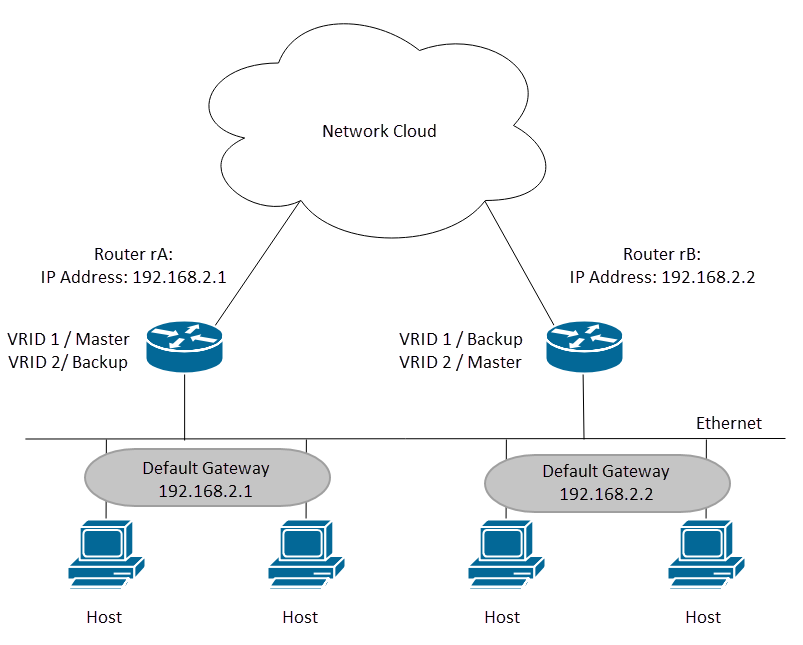
In this topology, two virtual routers are configured. For virtual router 1, Router A is the owner of IP address 192.168.2.1 and is the virtual router Active, and Router B is the virtual router Standby to Router A. Clients 1 and 2 are configured with the default gateway IP address of 192.168.2.1. For virtual router 2, Router B is the owner of IP address 192.168.2.2 and virtual router Active, and Router A is the virtual router Standby to Router B. Clients 3 and 4 are configured with the default gateway IP address of 192.168.2.2.
In this document, we will be configuring the first topology where Router A is the Active and Router B is acting as the Standby. If Router A fails then Router B will become the Active router.
If you are unfamiliar with the terms used below, check out Cisco Business: Glossary of New Terms.
Objective
This article provides instructions on how to configure VRRP settings on your switches through the Command Line Interface (CLI).
Applicable Devices
- SG550X Series
Software Version
- 2.3.0.130
Configure VRRP Virtual Routers on a Switch
Step 1. SSH to the switch. The default username and password is cisco/cisco. If you have configured a new username or password, enter the credentials instead.
Note: To learn how to access an SMB switch CLI through SSH or Telnet, click here.
Note: The commands may vary depending on the exact model of your switch. In this example, SG550XG-24T is used.
Step 2. From the privileged EXEC mode of the switch, enter the Global Configuration mode by entering the following:
SG550XG#configure terminal
Step 3. To configure the VRRP virtual router settings on a VLAN interface, enter the following command:
SG550XG#interface [vlan-id]In this example, we use interface vlan 1 to configure VRRP virtual router settings.

Step 4. To define an IP address of a virtual router, use the vrrp ip command in Interface Configuration mode. The IP interface of the VRRP router and the virtual group must be in the same IP subnet. A virtual router comes into existence when it has one or more participating VRRP routers. A VRRP router can use their real IP address for the VRRP group, allowing that VRRP router to become the Active of the VRRP group. You can also assign a virtual IP address that is not assigned to any router interface, but the router with the highest priority will become the Active. There can only be one owner for the VRRP group.
SG550XG#(config)#vrrp [vrid] ip [ip-address]- vrid – Virtual router identifier on the interface for which VRRP is being defined. The range is 1-255.
- ip-address – Virtual router’s IP address.
For this demonstration, we used the command vrrp 1 ip 192.168.2.1 to set the IP address of 192.168.2.1 for the virtual router.
Note: To remove the IP address, use the no vrrp [vrid] ip [ip-address] command.

Step 5. To enable the VRRP virtual router on the interface, use the following command:
SG550XG#(config-if)#no vrrp [vrid] shutdown- vrid – Virtual router identifier on the interface for which VRRP is being defined. The range is 1-255.
We will be entering no vrrp 1 shutdown to enable VRRP virtual router on the interface.
Note: To disable the VRRP virtual router on the interface, use the vrrp shutdown command in Interface Configuration mode. When a VRRP virtual router is disabled on an interface, its configuration is not removed.

Step 6. To assign a description to the VRRP virtual router, use the following command in Interface Configuration mode.
SG550XG#(config-if)#vrrp [vrid] description [text]- vrid – Virtual router identifier on the interface for which VRRP is being defined. The range is 1-255.
- text – Text that describes the purpose or use of the virtual router. The parameter may contain 0-160 characters.
For this example, we entered the command vrrp 1 description VirtualRouter1 to assign the description VirtualRouter1 for our vrid 1.

Step 7. To define the supported VRRP version, use the vrrp version command in Interface Configuration mode. Choosing a version depends on how your network is setup. However, if your topology allows it, the latter version should be your choice. Keep in mind that version 3 supports IPv6 as well.
Note: Each switch needs to be configured with the same version for VRRP to function correctly.
SG550XG#(config-if)#vrrp [vrid] version [version number]- vrid – Virtual router identifier on the interface for which VRRP is being defined. The range is 1-255.
- 2 – VRRPv2 specified by RFC3768 is supported. Received VRRPv3 messages are dropped by the VRRP virtual router. Only VRRPv2 advertisements are sent. VRRPv2 only supports IPv4 addresses. The timers are in seconds and uses 224.0.0.18 for the multicast address. VRRP needs to be enabled on per interface basis and node with the same priority value but higher IP would cause preemption.
- 3 – VRRPv3 specified by RFC5798 is supported without VRRPv3 support (8.4, RFC5798). Received VRRPv2 messages are dropped by the VRRP virtual router. Only VRRPv3 advertisements are sent. VRRPv3 supports usage of IPv4 and IPv6 addresses. The timers are in milliseconds and use 224.0.0.18 for IPv4 multicast and FF02:0:0:0:0:0:0:12 for IPv6. VRRP needs to be enabled globally and only higher priority will cause preemption.
- 2&3 – VRRPv3 specified by RFC5798 is supported with VRRPv2 support (8.4, RFC5798). Received VRRPv2 messages are treated by the VRRP virtual router. VRRPv3 and VRRPv2 advertisements are sent.
For this demonstration, we will be using version 2 by entering the command vrrp 1 version 2.

Step 8. To define a real VRRP address that will be used as the source IP address of VRRP messages, enter the following command below in Interface Configuration mode. Each VRRP router supporting a virtual router uses their own IP address as the source IP address in their outgoing VRRP messages for the virtual router.
SG550XG#(config-if)#vrrp [vrid] source-ip [ip-address]- vrid – Virtual router identifier on the interface for which VRRP is being defined. The range is 1-255.
- ip-address – VRRP router’s IP address: one of IP addresses of VRRP router defined on the same interface.
In this example, we entered the switch IP address as the source-ip address by typing in the command vrrp 1 source-ip 192.168.2.1.

Step 9. (Optional) To define Virtual Router Redundancy Protocol (VRRP) priority, use the command vrrp priority command in Interface Configuration mode.
SG550XG#(config-if)#vrrp [vrid] priority [priority number]- vrid – Virtual router identifier on the interface for which VRRP is being defined. The range is 1-255.
- Priority – Virtual router priority. The range is 1-254.
For this demonstration, the switch is the owner and has a priority of 255.
Note: The default priority for owner is 255 and cannot be changed. For non-owner, the default priority is 100. The picture below shows an example of how the command should be typed but was not entered.

Step 10. To enable Virtual Router Redundancy Protocol (VRRP) preemption, use the preempt command in Interface Configuration mode. By default, the VRRP router being configured with this command will take over as Active virtual router for the group if it has a higher priority than the current Active virtual router. The router that is the IP address owner will preempt, regardless of the setting of this command.
SG550XG#(config-if)#vrrp [vrid] preemptNote: To disable VRRP preemption to the specified VRRP virtual router, use the following command: no vrrp [vrid] preempt.

Step 11. To set the VRRP in accept mode, enter the following command:
SG550XG#(config-if)#vrrp [vrid] accept mode [accept | drop]The options are defined as:
- vrid – Virtual router identifier on the interface for which VRRP is being defined. The range is from 1 to 255.
- accept – The virtual router in Active state will accept packets addressed to the IP address of the virtual router as its own even if it is not the address owner.
- drop – The vritual router in Active state will drop packets addressed to the virtual router IP address even if it is not the address owner.
In this example, the Active is configured to accept packets by using the command vrrp 1 accept mode accept.

Step 12. To define the interval between successive advertisements by the Active VRRP virtual router, use the vrrp timers advertise command in Interface Configuration mode. In this example, we left the timers advertisement as the default setting of 1 second. The picture below shows an example of how the command should be typed for 2 seconds.
SG550XG#(config-if)#vrrp [vrid] timers advertise msec [msec] intervalThe options are defined as:
- vrid – Virtual router identifier on the interface for which VRRP is being defined. The range is from 1 to 255.
- msec – (Optional) Changes the unit of the advertisement time from seconds to milliseconds. Without the keyword, the advertisement interval is in seconds.
- interval – Time interval between successive advertisements. If keyword msec is present then the valid range is 50 to 40950 milliseconds. If keyword msec is omitted then the valid range is 1 to 40 seconds.

Step 13. (Optional) Object tracking is an independent process that manages creating, monitoring, and removing tracked objects such as the state of the line protocol of an interface, state of an IP route, or the reachability of a route. The tracking process periodically polls the tracked objects and notes any change of value. VRRP object tracking gives VRRP access to all the objects available through the tracking process. The priority of the virtual device is incremented or decremented based on the state of the object being tracked.
To learn more about object tracking for VRRPv3, please see the link: VRRPv3: Object Tracking Integration
To configure VRRP to track an object, enter the following:
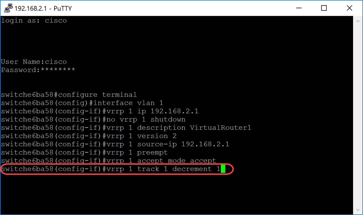
SG550XG#(config-if)#vrrp [vrid] track [object-id] decrement [priority]- vrid – Virtual router identifier on the interface for which VRRP is being defined. The range is from 1-255.
- object-id – Number of associates to track object with this VRRP router. Valid values for the number argument range from 1 to 64. This value was entered in the SLA tracks, click here for more information.
- priority – (Optional) Amount by which the priority for the router is decremented or incremented when the tracked object goes down or comes back up. The default value is 10. Decrements can be set to any value between 1 and 253.
In this example, we did not configure VRRP to track an object but we have typed in the command to show you an example of what it would look like.
Step 14. Enter the end command to go back to the Privileged EXEC mode.
SG550XG#(config-if)#end
Step 15. (Optional) In the Privileged EXEC mode of the switch, save the configured settings to the startup configuration file. Then press Y for Yes or N for No on your keyboard once the Overwrite file [startup-config]… prompt appears.
SG550XG#copy running-config startup-config
Step 16. Repeat steps 1 to 15 on the next switch to configure another virtual router. In this example, we have configured a second switch to become the Standby virtual router.

Verifying/Testing VRRP
Step 1. To display a brief or detailed status of one or all configurations VRRP virtual routers, enter the following command:
SG550XG#show vrrp {all | brief | interface [interface-id]}The options are:
- all – (Optional) Provides VRRP virtual router information about all VRRP virtual routers, including virtual routers in disable status. If no keyword is entered, the all keyword is applied.
- brief – (Optional) Provides a summary view of the VRRP virtual router information.
- interface interface-id – (Optional) Interface identifier.
In this example, we used show vrrp all.

Step 2. On the second switch, we have used the following command to display a detailed VRRP router information.
SG550XG#show vrrp all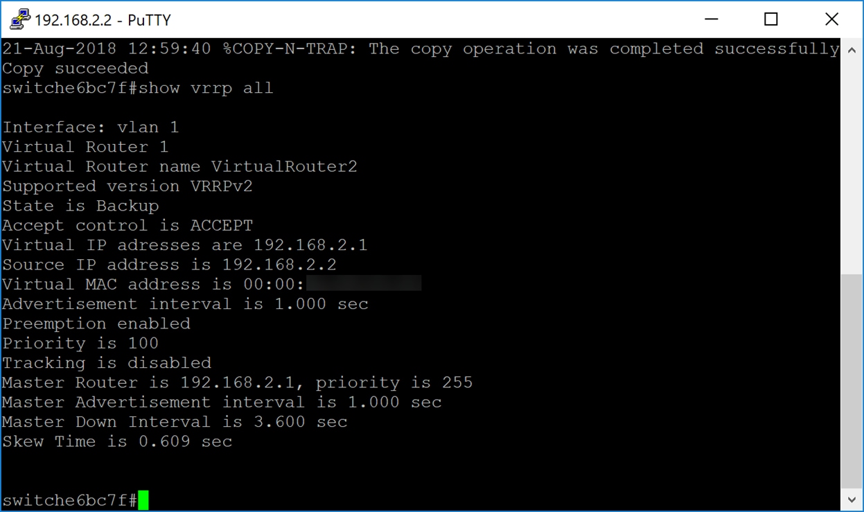
Step 3. This step shows an example of what happens when the first switch (Active) goes down. The second switch (Standby) becomes the Active like the example shown below. The state is Active for the second switch with the source IP address of 192.168.2.2.

Conclusion
You should now have successfully configured VRRP on a SG550X switch through the CLI.