Using Ping and Traceroute on the SG550XG and SG350XG
Available Languages
Objective
The SG550XG and SG350XG includes built-in ping and traceroute tools, which can be used to test the switch’s network communications. Ping uses ICMP (Internet Control Message Protocol) echo packets to test the reachability of a host on the network, and returns information such as round-trip time and packet status. Traceroute displays the route and time a packet takes when traveling to a network host.
The objective of this document is to show you how to use ping and traceroute on the SG550XG and SG350XG.
Applicable Devices
• SG550XG
• SG350XG
Software Version
• v2.0.0.73
Using the Ping and Traceroute Tools
Ping
Step 1. Log in to the web configuration utility and choose Administration > Ping. The Ping page opens.
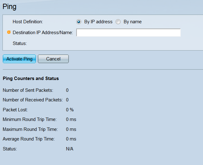
Step 2. In the Host Definition field, select a radio button to specify how the remote host will be identified. Select By IP address to designate the host by its IP address. Select By name to designate the host by its hostname. If you are on the Basic display mode, skip to Step 7 (the Display Mode can be changed with the drop-down list in the top-right corner of the web configuration utility).
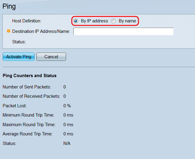
Step 3. If you are viewing the Ping page in Advanced display mode, several more fields are available. In the IP Version field, select a radio button to choose what IP version the switch will use when pinging. Select Version 4 to use IPv4, and Version 6 to use IPv6.

Step 4. In the Source IP drop-down list, select the IP address that the switch will send the ping from. The default is Auto, which tells the switch to compute the source address based on the destination address. If you selected Version 6 in the IP Version field, continue to Step 5; otherwise, skip to Step 7.

Step 5. In the Destination IPv6 Address Type field, select a radio button to indicate the type of the destination’s IPv6 address.

The options are:
• Link Local – The IP address uniquely identifies hosts on a single network link. A link local address has a prefix of FE80, is not routable, and can only be used for communication on the local network. If a link local address exists on the interface, this entry replaces the address in the configuration.
• Global – The address is a global unicast IPv6 address that is visible and reachable from other networks. If you select this option, skip to Step 7.
Step 6. If you selected Link Local from the Destination IPv6 Address Type field, choose a link local interface from the Link Local Interface drop-down list.

Step 7. In the Destination IP Address/Name field, enter the remote host’s IP address or hostname, depending on your selection in the Host Definition field. If you are on the Basic display mode, skip to Step 10.
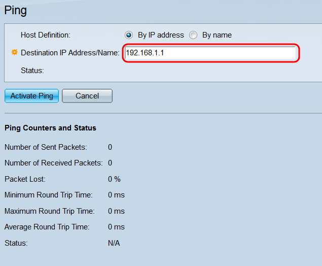
Step 8. In the Ping Interval field, choose a radio button to specify the length of time the switch waits in between sending packets. Select Use Default to use the default setting (2000 ms), or User Defined to enter a custom length of time (the range is 0-65535).

Step 9. In the Number of Pings field, choose a radio button to specify the number of pings the switch will send to the destination. Select Use Default to use the default setting (4 pings), or User Defined to enter a custom number (the range is 0-65535).
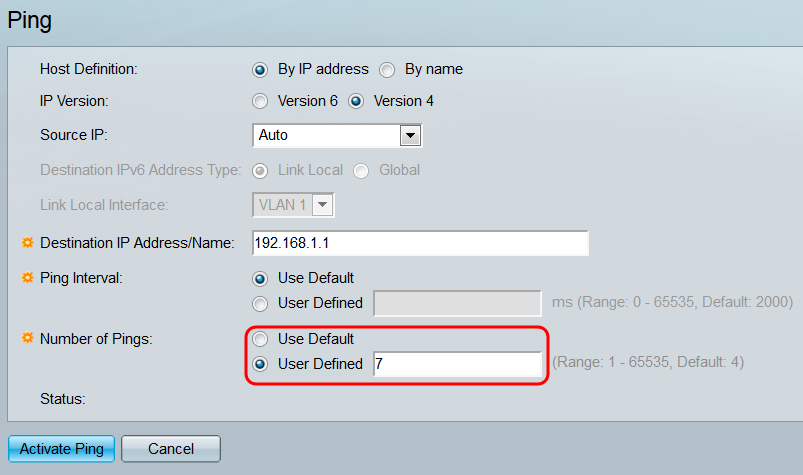
Step 10. Click Activate Ping to start the ping, or click Cancel to clear the settings.

Step 11. While the ping is processing, a loading bar will appear. Click the Stop Ping button underneath this bar to cancel the ping.
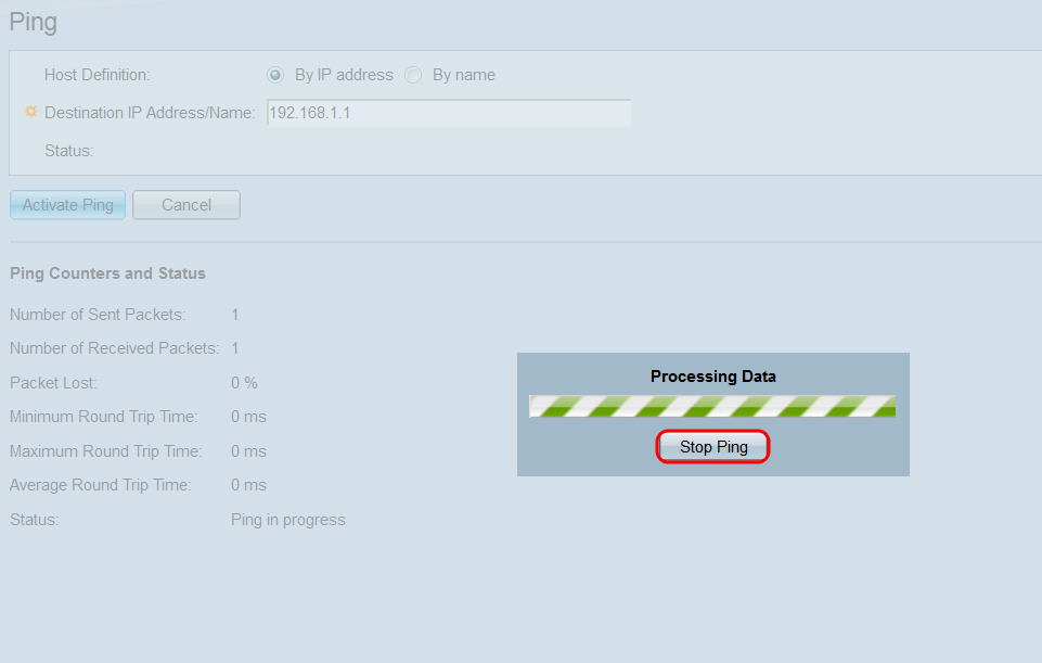
Step 12. When the ping finishes, several fields on the page will update with information.
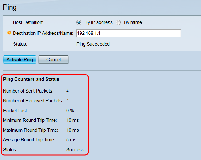
The fields are:
• Number of Sent Packets – Shows the total number of ICMP echo request packets sent to the remote host.
• Number of Received Packets – Shows the total number of ICMP echo reply packets received from the remote host.
• Packet Lost – Shows the percentage of echo request packets that never received a corresponding echo reply packet.
• Minimum Round Trip Time – Shows the quickest packet round-trip time out of all the packets sent.
• Maximum Round Trip Time – Shows the slowest packet round-trip time out of all the packets sent.
• Average Round Trip Time – Shows the average round-trip time out of all the packets sent.
• Status – Shows the return status of the ping.
Traceroute
Step 1. Log in to the web configuration utility and choose Administration > Traceroute. The Traceroute page opens.

Step 2. In the Host Definition field, select a radio button to specify how the remote host will be identified. Select By IP address to designate the host by its IPv4 address. Select By name to designate the host by its hostname. If you are on the Basic display mode, skip to Step 5. If you selected By name in this field, and are in Advanced display mode, skip to Step 4.
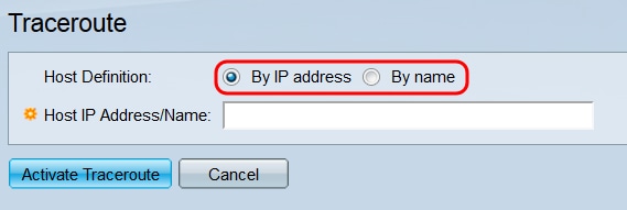
Step 3. If you are viewing the Traceroute page in Advanced display mode, several more fields are available (the Display Mode can be changed with the drop-down list in the top-right corner of the web configuration utility). In the IP Version field, select a radio button to choose what IP version the switch will use when running the traceroute. Select Version 4 to use IPv4, and Version 6 to use IPv6.

Step 4. In the Source IP drop-down list, select the IP address that the switch will send the traceroute from. The default is Auto, which tells the switch to compute the source address based on the destination address.

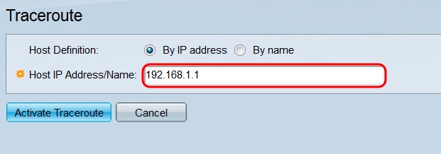
Step 5. In the Host IP Address/Name field, enter the remote host’s IP address or hostname, depending on your selection in the Host Definition field. If you are on the Basic display mode, skip to Step 8.
Step 6. In the TTL field, choose a radio button to specify the maximum number of hops that the traceroute will permit. The TTL (time-to-live) feature is used to prevent the packet from being stuck in an endless loop; if a packet exceeds its TTL value, the next router it arrives at will drop it and sends an ICMP Time Exceeded packet back to the switch. Select Use Default to use the default setting (30), or User Defined to enter a custom number (the range is 1-255).
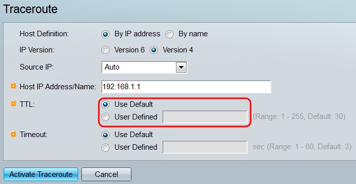
Step 7. In the Timeout field, choose a radio button to specify the amount of time the switch will wait for a return packet before declaring it lost and moving on to the next packet. Select Use Default to use the default setting (3 ms), or User Defined to enter a custom number (the range is 1-60).

Step 8. Click Activate Traceroute to start the traceroute, or click Cancel to clear the settings.

Step 9. While the traceroute is processing, a loading bar will appear. Click the Stop Traceroute button underneath this bar to cancel the traceroute.

Step 10. When the traceroute completes, the Traceroute Table appears, which holds all of the information returned. Traceroute sends three packets to the remote host, and each packet’s individual information is under each Round Trip 1-3 field.

The fields are:
• Index – Shows the number of the hop.
• Host – Shows the IP address of a stop on the route.
• Round Trip 1-3 – Shows each packet’s traceroute information.
– Time (ms) – Shows the round-trip time to the stop.
– Status – Shows whether the packet successfully reached the stop.
Revision History
| Revision | Publish Date | Comments |
|---|---|---|
1.0 |
11-Dec-2018 |
Initial Release |
 Feedback