Setting System Time Dynamically from a SNTP Server for 200, 300, & 500 Series Managed Switches
Available Languages
Objective:
System time can be set manually by the user, dynamically from a Simple Network Time Protocol (SNTP) Unicast/ Multicast/Anycast server, or synchronized from the PC running the GUI. Synchronized system clocks provide a frame of reference for all devices on the network. Network time synchronization is critical to managing, securing, and debugging networks. Synchronized Time also plays an important role in shared file systems because it eliminates confusion with version differences and modification times. The switch always configures the time, time zone and GUI as part of the boot process.
The objective of this document is to show you how to configure the time settings on the SG200, SG300 and SG500 Series switches for SNTP Network Time Synchronization.
Applicable Devices:
• Cisco Small Business 200 series Managed Switches
• Cisco Small Business 300 series Managed Switches
• Cisco Small Business 500 series Managed Switches
Software Versions:
• 1.3.0.59
Setting the System Time:
Step 1. Log into the web configuration utility. The default username is “cisco” and the default password is “cisco”.
Step 2. Navigate to Administration > Time Settings > System Time. The System Time page opens:
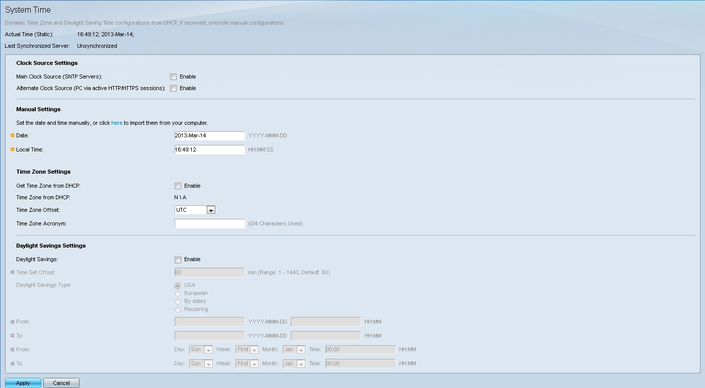
At the top of the page the following fields are displayed:
• Actual Time (Static) – Displays the actual time on the device. It also displays the time zone if specified.
• Last Synchronized Server – Displays information from the SNTP Server including the address, stratum, and type of server. If your device does not connect to an SNTP server this field displays “Unsynchronized”.
Step 3. Under Clock Source Settings, click the Enable checkbox to the right of the Main Clock Source (SNTP Servers).
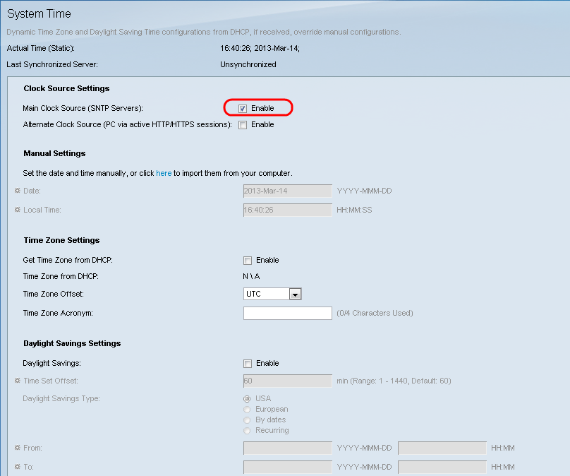
Step 4. At the bottom of the System Time page click Apply to save the current settings.
Step 5. Navigate to Administration > Time Settings > SNTP Unicast. The SNTP Unicast opens:

This page displays the following information for each Unicast SNTP server:
• SNTP Server — Specifies the SNTP server IP address, the preferred server, or the hostname that is chosen according to its stratum level.
• Poll Interval — Displays whether polling is enabled or disabled.
• Authentication Key ID — Key identification used to communicate between the SNTP server and the device.
• Stratum Level — Distance from the reference clock (expressed as a numerical value). An SNTP server cannot be the primary server (stratum level 1) unless polling interval is enabled.
• Status — SNTP server status. The possible values are:
– Up — SNTP server is currently operating normally.
– Down — SNTP server is currently not available.
– Unknown — SNTP server is currently being searched for by the device.
– In Process — Occurs when the SNTP server has not fully trusted its own time server (i.e. when first booting up the SNTP server).
• Last Response — Date and time of the last response received from this SNTP server.
• Offset — Specifies the average offset of the server's clock relative to the local clock (in milliseconds). The host determines the value of this offset using the algorithm described in RFC 2030.
• Delay — Average round-trip delay time of packets traveling over the network between server and local clocks (in milliseconds). The host determines the value of this delay using the algorithm described in RFC 2030.
• Source — How the SNTP server was defined.
• Interface — The interface on which packets are received.
Step 6. At the bottom of the Unicast SNTP Server Table field click Add.

Step 7. After clicking Add, the Add SNTP Server page opens:
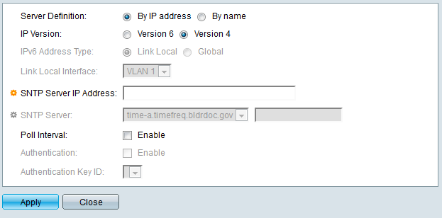
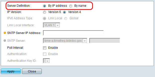
Step 8. In the Server Definition field, select By IP address if the SNTP server is going to be identified by its IP address, or By name if you are going to select a well-known SNTP server by name from the list. If By name is selected, skip to step 12.
Note: To specify a well-known SNTP server, the device must be connected to the Internet and be configured to use either a DNS server or DHCP to identify a DNS server. (See DNS Settings)
Step 9. In the IP Version field, select the version of the IP address: Version 6 or Version 4. If Version 4 is selected, skip to step 12. Version 4 is selected by default.
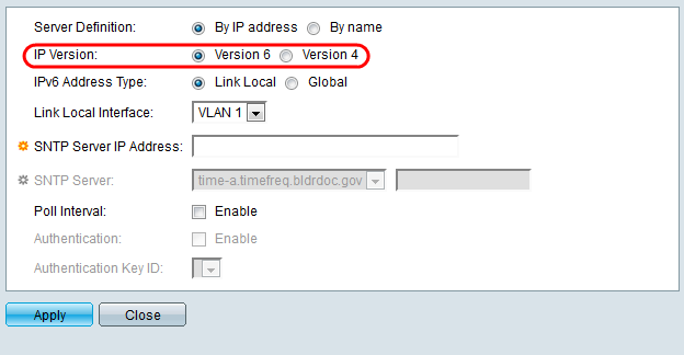
Step 10. (Optional) If you chose IPv6, select the IPv6 address type next to the IPv6 Address Type field. If Global is selected, skip to Step 12.
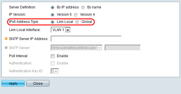
• Link Local — The IPv6 address uniquely identifies hosts on a single network link. A link local address has a prefix of FE80, is not routable, and can only be used for communication on the local network. Only one link local address is supported. If a link local address exists on the interface, this entry replaces the address in the configuration.
• Global — The IPv6 address is a global Unicast IPV6 type that is visible and reachable from other networks.
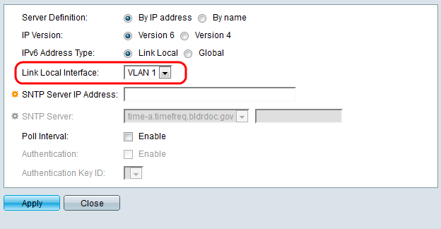
Step 11. If you chose IPv6 Address Type Link Local in step 10, select the link local interface from the list.
Step 12. If By IP address was selected in the Server Definition field, enter the SNTP server IP address in the SNTP Server IP Address field. The format depends on which address type was selected.
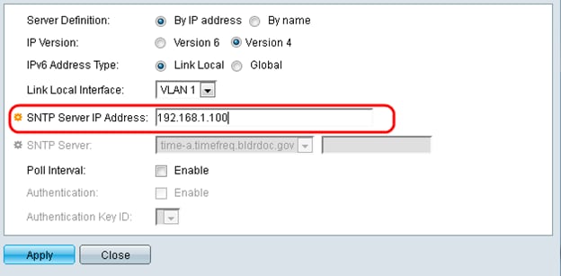
If By Name was selected in the Server Definition field, select the desired SNTP Server from the SNTP Server drop down list.
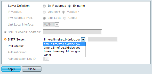
When specifying an SNTP server, if choosing to identify it by hostname, three suggestions are given in the GUI:
– time-a.timefreq.bldrdoc.gov
– time-b.timefreq.bldrdoc.gov
– time-c.timefreq.bldrdoc.gov
Step 13. In the Poll Interval field, check the Enable checkbox to allow polling for system time information on the SNTP server. All SNTP servers that are registered for polling are polled, and the clock is selected from the server with the lowest stratum level (distance from the reference clock) that is reachable. The server with the lowest stratum is considered to be the primary server. The server with the next lowest stratum is a secondary server, and so forth. If the primary server is down, the device polls all servers with the polling setting enabled, and selects a new primary server with the lowest stratum.
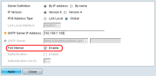
If you want to enable SNTP Authentication refer to Enabling SNTP Authentication on 200, 300, & 500 Series Managed Switches.
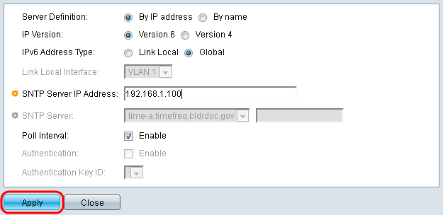
Step 14. Click Apply at the bottom of the current page to return to the SNTP Unicast page.
The page should show adjusted values in the Unicast SNTP Server Table

Step 15.In the SNTP Client Unicast field, click the Enable checkbox.

Step 16. Click Apply.

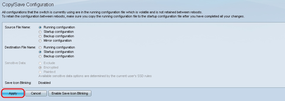
Step 17. From here, you can click Save located at the top right corner of the page, or the Copy/Save Configuration page link.

Step 18. Save the running configuration into the startup configuration by choosing the Running Configuration in the Source File Name field and the Startup Configuration option in the Destination File Name field.
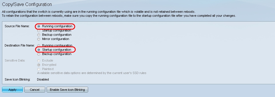
Step 19. At the bottom of the Copy/Save Configuration page click Apply to save the configuration settings.
Revision History
| Revision | Publish Date | Comments |
|---|---|---|
1.0 |
13-Dec-2018 |
Initial Release |
 Feedback