Rapid Spanning Tree Protocol (RSTP) Configuration on the 200/300 Series Managed Switches
Available Languages
Objectives
Loops in a network occur when alternate routes exist between hosts. Loops in an extended network can cause Layer 2 switches to forward traffic indefinitely, which results in increased traffic and reduced network efficiency. Spanning Tree Protocol (STP) provides a single path between any two end stations in order to prevent loops. Rapid Spanning Tree Protocol (RSTP) detects network topologies to provide faster convergence and create a network without loops. This is most effective when the network topology is naturally tree structured.
This article explains how to configure RSTP per port on the 200/300 Series Managed Switches.
Applicable Devices
- SF/SG 200 and SF/SG 300 Series
Software Version
- 1.3.0.62
Spanning Tree Global Setup
First, you need to make sure the parameters for RSTP are enabled in the switch.
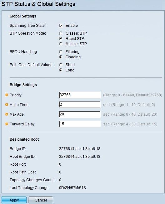
Step 1. Log in to the web configuration utility and choose Spanning Tree > STP Status & Global Settings. The STP Status & Global Settings page opens:

Step 2. Check the Enable check box in the Spanning Tree field to enable STP.
Step 3. Click the Rapid STP radio button in the STP Operation Mode field to use RSTP as the operation mode of STP.
Step 4. Click on of the available options in the BPDU Handling field to handle Bridge Protocol Data Unit (BPDU) packets when STP is disabled:
Step 5. Click on one of the available options in the Path Cost Default Values field to assign default path costs:
- Filtering — This option filters BPDU packets.
- Flooding — This option floods BPDU packets.
- Short — This option uses a range from 1 to 65,535 for port path costs.
- Long — This option uses a range from 1 to 200,000,000 for port path costs.
Step 6. Click Apply to save your settings.
Enable Rapid Spanning Tree on a Port
Step 1. Log in to the web configuration utility and choose Spanning Tree > RSTP Interface Settings. The RSTP Interface Settings page opens:

Step 2. If a connected device is discovered via STP, choose the interface that is connected to the device and click Activate Protocol Migration. This performs a test on the connected device to see the type of STP. The switch then communicates with the connected device through the use of the respective STP type of the connected device
Step 3. In the Filter drop-down list, choose whether to configure a port or a LAG (Link Aggregation Group).
Step 4. Click the radio button of the port /LAG you want to enable RSTP.
Step 5. Click Edit. The Edit RSTP Interface Settings window appears.

Step 6. In the Point to Point Administrative Status field, click one of the available options:
Note: Ports defined as Full Duplex are considered Point-to-Point port links.
The following information about the port/LAG is displayed:
- Enable — Enabling this feature will make this port as a RSTP edge port and brings it to forwarding mode quicker than normal STP.
- Disable — The port will not be considered as point-to-point for RSTP purposes, STP will work on regular speed.
- Auto — Determines switch status automatically by using RSTP BPDUs.
- Point to Point Operational Status — Displays enabled if point-to-point administrative distance is set to auto.
- Role — The role of the port as assigned by STP to provide STP path.
- Mode — The current spanning tree mode.
- Fast Link Operational Status — The status of the fast link.
- Port Status — RSTP status on the port.
Step 7. Click Apply to save your changes.
Revision History
| Revision | Publish Date | Comments |
|---|---|---|
1.0 |
10-Dec-2018 |
Initial Release |
 Feedback