Cisco Discovery Protocol (CDP) Local Information on 200/300 Series Managed Switches
Available Languages
Objectives
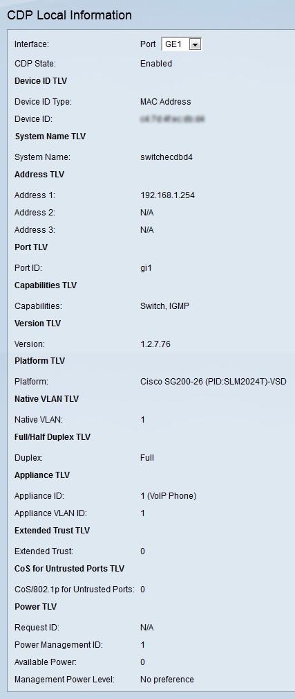
Cisco Discovery Protocol (CDP) is a Link-Layer Cisco proprietary protocol that allows Cisco devices to communicate regardless of IP connectivity. It is used primarily to communicate protocol addresses and device capabilities. CDP sends frames containing Type Length Values (TLVs), which are fields containing different properties of the port and/or connection. The CDP Local Information page displays information that is advertised by the CDP protocol about the local device.
This article explains the information displayed on the CDP Local Information page on 200 and 300 Series Managed Switches.
Applicable Devices
• SF/SG 200 and SF/SG 300 Series Managed Switches
Software Version
• v1.2.7.76
CDP Local Information
Step 1. Log in to the web configuration utility and choose Administration > Discovery - CDP > CDP Local Information. The CDP Local Information page opens:

Step 2. Choose the port that you want to display information for from the Interface drop-down list.
The following displays information that the port advertises in the CDP packets.
• CDP State — The state of CDP of the specified port.
• Device ID Type — The type of device ID advertised. This field displays MAC Address or Serial Number.
• Device ID — The device ID. This is either the MAC address or serial number of the switch.
• Address — The network layer address(es) assigned to the specified port.
• Port ID — The ID of the specified port.
• Capabilities — The advertised capabilities of the device. The switch advertises that it is capable of switching and using IGMP.
• Version — The current software version of the switch.
• Platform — The platform name, number, and Product ID (PID) of the switch.
• Native VLAN — The Native VLAN identifier.
• Duplex — Displays if the port is in half or full duplex mode. Half duplex mode will restrict link partners to one way communication. This means only one of the link partners can transmit data at a time. Full duplex mode allows the link partners to receive and transmit data simultaneously.
• Appliance ID — Type of device attached to the specified port. For most non-Cisco devices the Appliance ID will be 1.
• Appliance VLAN ID — The VLAN ID of the attached device.
• Extended Trust — The state of extended trust on the port. If the host or server from which the packet is received is trusted, that host is allowed to mark the packets with priority values. If the host or server from which the packet is received is not trusted, then the CoS for Untrusted Ports field is used.
• CoS/802.1p for Untrusted Ports — The CoS priority value given to all packets on the port if extended trust is disabled on the port.
• Request ID — The last power request ID received echoes the Request-ID field last received in a power requested TLV. It is 0 if no power requested TLV was received since the port last became active.
• Power Management ID — This field increments by 1 each time the Available-Power or Management Power fields change, a power requested TLV is received with a Request-ID field which is different from the last received set, or when the port goes down.
• Available Power — The amount of power consumed by the specified port in watts.
• Management Power Level — The request of the supplier to the powered device for the power consumption TLV. The 200/300 switches always display No Preference since the switch is a power provider.
Revision History
| Revision | Publish Date | Comments |
|---|---|---|
1.0 |
10-Dec-2018 |
Initial Release |
 Feedback