Add IP Multicast Group Addresses on the 200/300 Series Managed Switches
Available Languages
Objective
Multicast enables communication between users. With the 200/300 Series Managed Switches, you can define a multicast group via an IP address. When the switch receives a multicast packet via VLAN that is configured for multicast purposes, the VLAN maps the multicast packet to the IP address of the multicast group and all members of the group receive the multicast packet. With this option, you are able to select which interfaces on your switch are for multicast purposes which separate multicast traffic from the rest of the traffic.
This article explains how to configure IP Multicast Group Addresses on the 200/300 Series Managed Switches.
Applicable Devices | Firmware Version
- SF/SG 200 Series | 1.3.0.62 (Download latest)
- SF/SG 300 Series | 1.3.0.62 (Download latest)
Enable Bridge Multicast
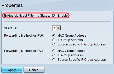
In order for IP multicast to work, bridge multicast must be enabled.
Log in to the Web Configuration utility and choose Multicast > Properties. The Properties page opens.
In the Bridge Multicast Filtering Status field, check the Enable check box.
Click Apply.
Configure IP Multicast Group Addresses
Add a Multicast Group Address
Step 1. Log in to the Web Configuration utility and choose Multicast > IP Multicast Group Address. The IP Multicast Group Address page opens.
Click Add. The Add IP Multicast Group Address window appears.
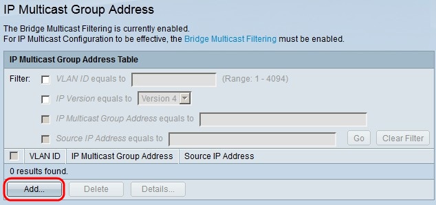
Step 2. In the VLAN ID field, enter the VLAN ID number of the VLAN of the IP multicast group.
In the IP version field, click one of the following:
- Version 6 - To use a version 6 multicast IP address.
- Version 4 - To use a version 4 multicast IP address.
In the IP Multicast Group Address field, enter a valid multicast IP address. For version 4 IP addresses, the range is from 224.0.0.0 to 239.255.255.255. For version 6 IP addresses use the prefix of ff00::/8 and choose the desired type of multicast addresses.
(Optional) To enable a specific source IP address from where the multicast packets are sent, check the Include check box.
If the Source Specific check box is checked, enter the version 6 or version 4 source IP address in the Source IP Address field.
Click Apply.
Filter IP Multicast Groups
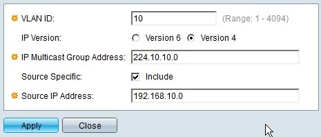
Step 1. To find a specific multicast group, you can use filters. Check the appropriate check boxes:
- VLAN ID equals to - To filter the multicast group with its VLAN ID. Enter in the field the respective VLAN ID.
- IP Version equals to - To filter the multicast group based on its IP version. Choose the desired IP version from the drop-down list.
- IP Multicast Group Address equals to - To filter the multicast group with its IP address, enter in the field the appropriate IP address of the multicast group.
- Source IP Address equals to - To filter the multicast group with its source IP address. Enter in the field the source IP address of the device that sends multicast packets.
Click Go.
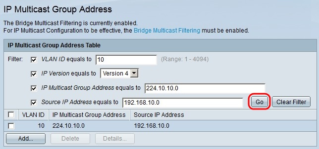
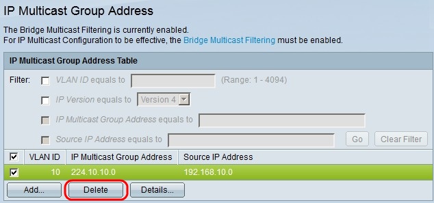
Step 2. (Optional) To delete an IP multicast group, check the check box of the IP multicast group and click Delete.
Add Interfaces to the IP Multicast Group
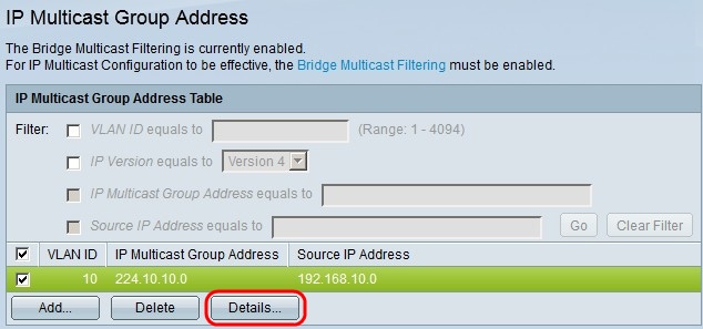
Step 1. Click Details. The IP Multicast Interface Settings window appears.
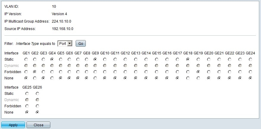
Step 2. In the Filter: Interface Type equals to drop-down list, choose whether to show the ports interfaces or the LAG (Link Aggregation Group) interfaces. A LAG combines individual interfaces into a single logical link, which provides an aggregate bandwidth of up to eight physical links.
Click Go.
For each interface, choose how the interface is associated with the IP multicast group. For each interface, click one of the following:
- Static - Adds the interface to the IP multicast group as a static member.
- Forbidden - Indicates that this interface is not allowed to join the IP multicast group.
- None - Indicates that this interface currently does not belong to the IP multicast group.
Click Apply.
Conclusion
You now know how to configure IP Multicast Group Addresses on the 200/300 Series Managed Switches.
For links to dozens of articles on this series of switches or to download the latest firmware, click here.