Initial Configuration on 200/300 Series Managed Switches
Available Languages
Objective
At its most basic definition, the job of a network switch is to receive messages from one connected device and forward them to another connected device. The 200/300 Series switches are capable of many more specialized and complicated tasks. One way to configure your switch is with the graphical user interface or GUI. This article explains how to access the GUI and configure the IP address of a 200/300 Series Managed Switch.
Applicable Devices
- SF/SG 200 and SF/SG 300 Series Managed Switches
Software Version
- v1.2.7.76
Access the Graphical User Interface (GUI)
Step 1. Connect the switch to a power supply to turn it on. The switch accepts voltage in the range of 100-240V.
Step 2. Connect one end of an Ethernet cable to your computer and the other end to an available port on the switch.
Step 3. Configure your computer with an IP address in the same subnet as the IP address of the switch by one of two methods.
- Static —Assign your computer a static IP address in the same subnet as the switch. The default IP address of the switch is 192.168.1.254, which means you must choose an IP address that is not in use and between 192.168.1.2 - 192.168.1.253.
- Dynamic —Use a DHCP server that is connected to both the switch and your computer. The DHCP server will assign the computer and the switch IP addresses.
Note: When the factory default IP address 192.168.1.254 is in use, the System LED flashes green continuously. If the default IP address is not in use, the System LED will remain solid green.
Step 4. Open a web browser window.
Step 5. Enter the IP address of the switch in the address bar and press Enter. The Managed Switch Login page opens:

Step 6. Enter the username in the Username field. The default username is cisco.
Step 7. Enter the password in the Password field. The default password is cisco. Passwords are case sensitive.
Step 8. Choose the desired language from the Language drop-down list.
Step 9. Click Log In to log in to the device.
Change the IP Address of the Switch
Method 1: Statically Assign TCP/IP Settings
Step 1. Access the GUI of the switch and log in as described in the section Access the Graphical User Interface (GUI).
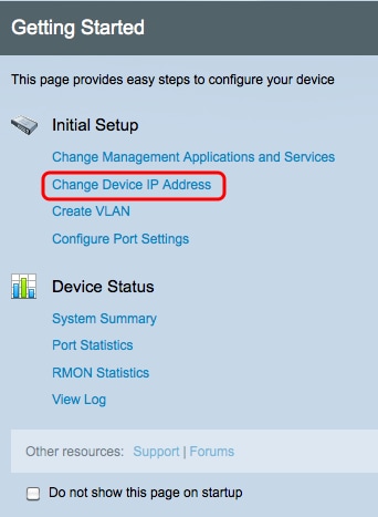
Step 2. Click Getting Started. The Getting Started page opens:

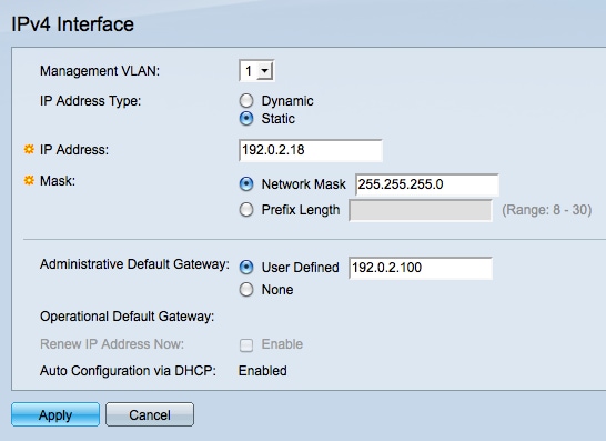
Step 3. Click Change Device IP Address to change the IP address of the switch. The IPv4 Interface page opens:

Step 4. Choose a VLAN number from the Management VLAN drop-down list. Only devices on the management VLAN will be able to access the GUI of the switch. The default management VLAN of the switch is VLAN1. Refer to the article VLAN Configuration on the 200/300 Series Managed Switches for help with VLANs.
Step 3. Click the Static radio button in the IP Address Type field to manually assign an IP address.
Step 4. Enter the desired IP address of the switch in IP Address field.
Step 5. Click the radio button that corresponds to the method used to determine the subnet mask in the Mask field.
Step 6. Click the radio button that corresponds with the method used to determine the administrative default gateway in the Administrative Default Gateway field.
- Network Mask — Enter the IP address mask.
- Prefix Length — Enter the IP address prefix length.
- User Defined — Enter the IP address of the default gateway.
- None — No default gateway will be configured. If no default gateway is chosen, the switch will not be able to communicate with devices that are outside of the IP subnet of the switch.
Step 7. Click Apply to save the settings.
Method 2: Dynamically Assign TCP/IP Settings
Step 1. Access the GUI of the switch and log in as described in the section Access the Graphical User Interface (GUI).
Step 2. Click Getting Started. The Getting Started page opens:

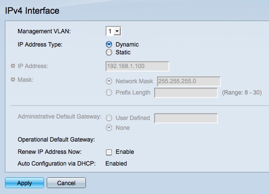
Step 3. Click Change Device IP Address to change the IP address of the switch. The IPv4 Interface page opens:

Step 4. Choose a VLAN number from the Management VLAN drop-down list. Only devices on the management VLAN will be able to access the GUI of the switch. The default management VLAN of the switch is VLAN1. Refer to the article VLAN Configuration on the 200/300 Series Managed Switches for help with VLANs.
Step 5. Click the Dynamic radio button in the IP Address Type field to dynamically assign an IP address.
Step 6. (Optional) Check the Enable check box in the Renew IP Address Now field to renew the IP address of the switch.
The Auto Configuration via DHCP field shows the status of the Auto Configuration feature. Refer to the article Dynamic Host Configuration Protocol (DHCP) Server Auto Configuration on the 200/300 Series Managed Switches for more information.
Step 7. Click Apply to save the settings.
Revision History
| Revision | Publish Date | Comments |
|---|---|---|
1.0 |
10-Dec-2018 |
Initial Release |
 Feedback