Setup Spanning Tree Protocol (STP) on a Interface on the 200/300 Series Managed Switches
Available Languages
Objectives
Spanning Tree Protocol (STP) creates a unique path between the different end points in a network in order to avoid loops. A network loop occurs when there are multiple paths between the source and the destination. A loop creates inconsistency and can slow down your network. STP ensures that a network is loop-free. You can create a custom configuration of STP on a given interface for security purposes. The 200/300 Series Managed Switches offers different STP features that you can use to add more security to your network.
This article explains how to configure STP and its features on a specific interface on 200/300 Series Managed Switches.
Applicable Devices
- SF/SG 200 and SF/SG 300 Series Managed Switches
Software Version
- 1.3.0.62
Setup STP Interface
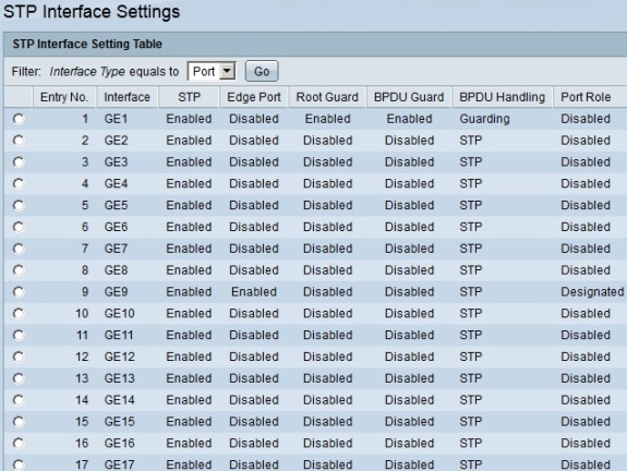
Step 1. Log in to the web configuration utility and choose Spanning Tree > STP Interface Settings. The STP Interface Settings page opens:

Step 2. Choose an interface from the Interface Type drop-down list.
Step 3. Click Go to display a list of ports or LAGs on the interface.

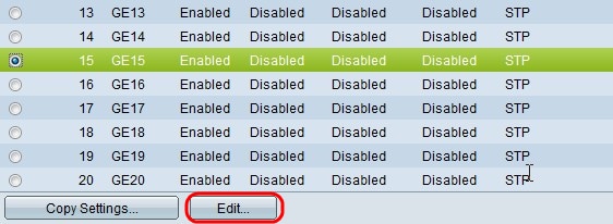
Step 4. Click the radio button of the port or LAG you want to modify and click Edit. The Edit STP Interface Setting window appears.

Step 5. (Optional) Click the radio button that corresponds to the desired interface in the Interface field.
- Port — From the Port drop-down list, choose the port to configure. This will only affect the single port chosen.
- LAG — From the LAG drop down list, choose the LAG to configure. This will affect the group of ports defined in the LAG configuration.
Step 6. Check Enable in the STP field to enable STP on the interface.
Step 7. Click the radio button that corresponds to the desired use of fast link in the Edge Port field. Fast link is used to set a port automatically to the forwarding state when the port links up. Fast link optimizes the STP convergence.
- Enable — Enables fast link immediately.
- Auto — Enables fast link a few seconds after the interface becomes active. This allows STP to resolve loops before fast link is enabled.
- Disable — Disables fast link.
Step 8. Check Enable in the Root Guard field to enable Root Guard on the interface. This option provides a way to enforce the root bridge placement in the network. Root Guard is used to prevent a new connected device to take over as root bridge.
Step 9. Check Enable in the BPDU Guard field to enable Bridge Protocol Data Unit (BPDU) Guard on the interface. BPDU Guard allows the user to enforce the STP domain borders on port and keep the active topology predictable. Devices that are connected to a port that have BPDU enabled cannot affect the STP topology. When the switch receives a BPDU on the port with BPDU Guard enabled, the port is disabled and a SNMP trap is generated.
Step 10. Click the radio button that corresponds to the desired option in the BPDU Handling field. This determines how BPDU packets are managed when STP is disabled on the port. BPDUs are used to transmit STP information.
Step 11. Click the radio button that corresponds to the desired path cost in the Path Cost field. The path cost is the cost from the port to the root port. STP uses this value to ensure a loop free topology. The available options for path cost are:
- Use Global Settings — Uses the settings defined on the
- STP Status and Global Settings page.
- Filtering — Filters BPDU packets when STP is disabled on the interface.
- Flooding — Forwards the BPDU packets to all the interfaces when STP is disabled on the interface.
- Use Default — Use the default cost generated by the system.
- User Defined — Enter a value for the path cost in the User Defined field.
Step 12. From the Priority drop-down list, choose the priority value of the interface. The priority value determines port choice when a bridge has two ports connected in a loop. The lower the value, the higher priority the port has on the bridge.
These fields display statistics of the Interface:
- Port State — Current state of the specified port.
– Disabled — STP is disabled on the port. The port forwards traffic and learns MAC addresses.
– Blocking — The port is blocked. The port cannot forward traffic or learn MAC addresses. The port can forward BPDU data.
– Listening — The port cannot forward traffic and cannot learn MAC addresses.
– Learning — The port cannot forward traffic but can learn new MAC addresses.
– Forwarding — The port can forward traffic and can learn new MAC addresses.
- Designated Bridge ID — The bridge priority and MAC address of the designated bridge.
- Designated Port ID — The priority and interface of the selected port.
- Designated Cost — The cost of the port that is part of the STP topology. Ports with lower costs are less likely to be blocked if STP detects loops.
- Forward Transitions — The number of times the port has changed from the blocking state to the forwarding state.
- Speed — The speed of the port.
- LAG — The LAG to which the port belongs. The LAG settings would override the port settings.
Step 13. Click Apply.
The image below depicts the changes after the configuration.

Note: To apply an STP configuration of a single port to multiple ports, refer to the section Apply a STP Configuration to Multiple Ports.
Apply a STP Configuration to Multiple Ports
This section explains how to apply a STP configuration of a single port to multiple ports.
Step 1. Log in to the web configuration utility and choose Spanning Tree > STP Interface Settings. The STP Interface Settings page opens:

Step 2. Click the radio button of the port which you want to apply its configuration to multiple ports.
Step 3. Click Copy Settings. The Copy Settings window appears.

Step 4. In the to field, enter the range of ports that will have the same STP configuration of the port you chose in Step 2. You can use the port numbers or the name of the ports as input. You can enter each port separated by a comma such as 1, 3, 5 or GE1, GE3, GE5 or you can enter a range of ports such as 1-5 or GE1-GE5.
Step 5. Click Apply to save your configuration.
The below image depicts the application of a single port security configuration to multiple ports.

Revision History
| Revision | Publish Date | Comments |
|---|---|---|
1.0 |
13-Dec-2018 |
Initial Release |
 Feedback