Access the CLI via PuTTY using a Console Connection on 300 and 500 Series Managed Switches
Available Languages
Objective
Switches can be accessed and configured through the Command Line Interface (CLI). Accessing the CLI allows commands to be entered in a terminal based window. For a user who has had more experience with terminal commands, this may be an easier alternative to navigating the web configuration utility. Certain tasks such as recovering an administrator password can only be performed through the CLI. In order to access the CLI you must use an SSH client. PuTTY is a standard SSH client and can be found here. This document assumes you are connecting to the switch using PuTTY.
The objective of this document is to show you how to access the Command Line Interface (CLI) of a switch and a Secure Shell (SSH) client.
Note: Cisco 200 Series Small Business Managed Switches do not support the CLI.
Applicable Devices | Software Version
- Sx300 Series | 1.2.7.76 (Download latest)
- Sx350 Series | 1.2.7.76 (Download latest)
- SG350X Series | 1.2.7.76 (Download latest)
- Sx500 Series | 1.2.7.76 (Download latest)
- Sx550X Series | 1.2.7.76 (Download latest)
Accessing the CLI via PuTTY with a Console Connection
Step 1. Connect the switch to the computer using a standard 9-pin serial cable.
The Cisco DB9 to RJ45 Console Cable also supports console connections, but only if the switch has an RJ45 Console port. An RJ45 Console port resembles an Ethernet port and is labeled CONSOLE on the back of the switch.
Newer laptops don’t have Serial ports on them, so in this case you have to use a USB to Serial adapter. When plugging that into a computer it assigns a COM port number to it that is not COM1. If this is the case for you, you need to know where to look to find the correct COM port number when setting up the connection with PuTTY. Right-click on the Windows logo/Start menu and click on Device Manager to open it.
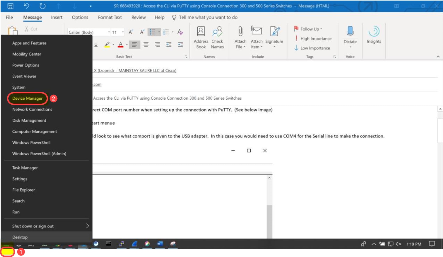
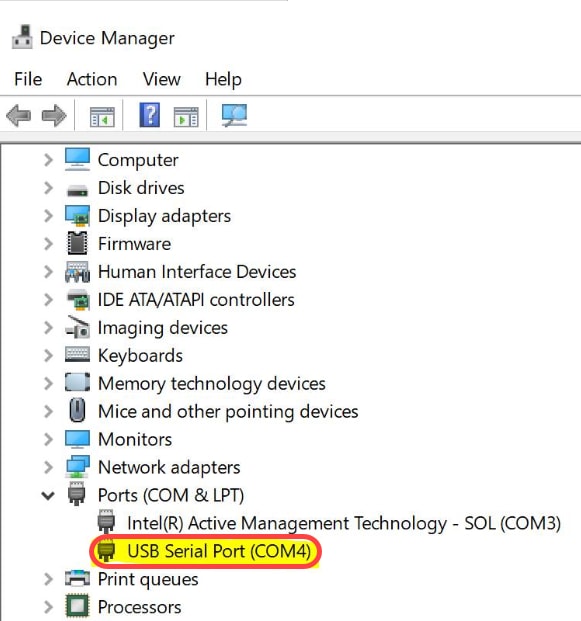
In the Device Manager, you would look to see what COM port is given to the USB adapter. In this case you would need to use COM4 for the Serial line to make the connection.
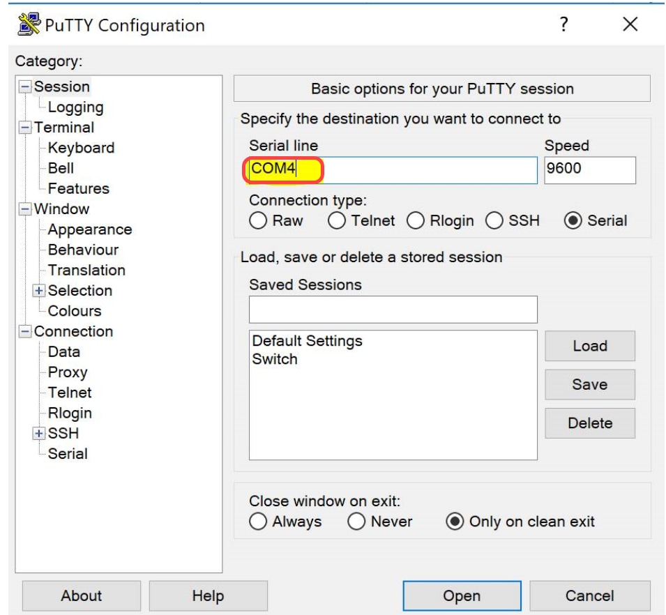
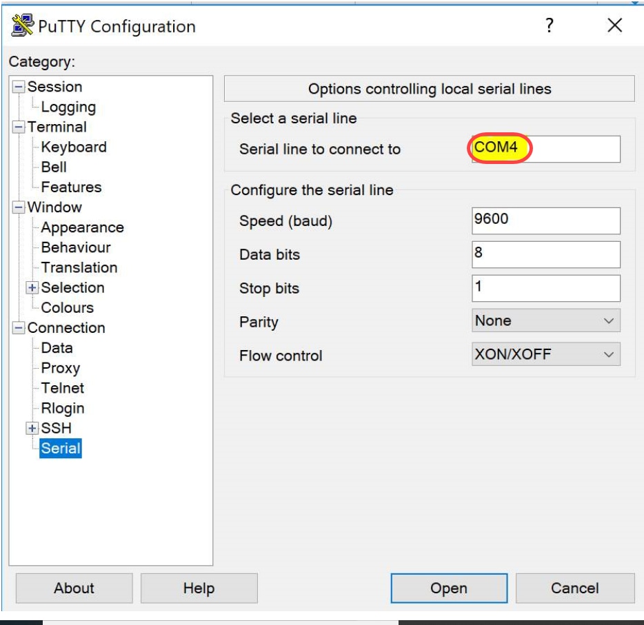
Step 2. Open the PuTTY application. The PuTTY Configuration window opens:
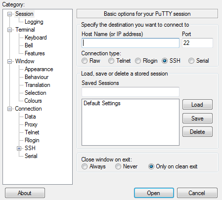
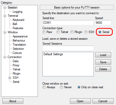
Step 3. Under the Connection Type field, click the Serial radio button.
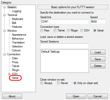
Step 4. In the Category navigation field, choose Serial.
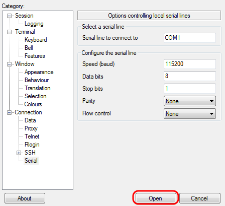
The Options controlling local serial lines page opens:
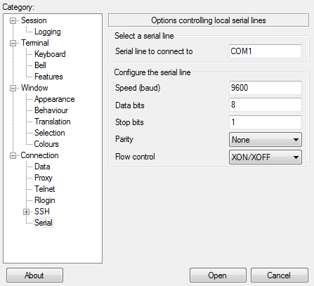
Step 5. In the Serial line to connect to field, enter the COM port that your device is connected to. The default COM port is COM1.
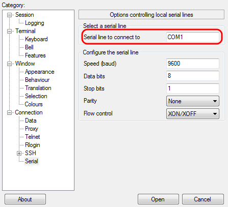
Step 6. In the Speed (baud) field, enter the digital transmission speed that is compatible with the switch. For 300 and 500 Series Managed Switches, the speed must be set to 115200.
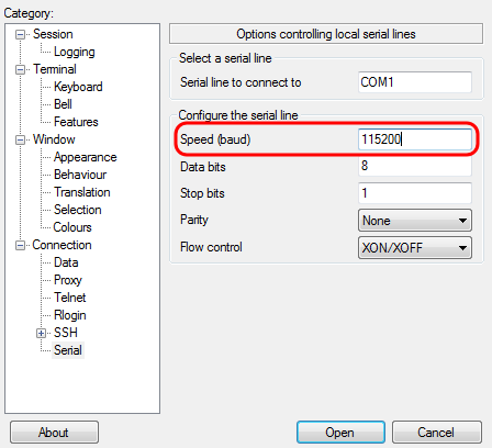
Step 7. In the Data bits field, enter the number of data bits used for each character. The recommended value is 8.
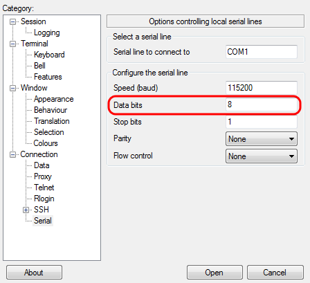
Step 8. In the Stop bits field, enter the number of bits to be sent at the end of every character. The stop bit informs the machine that it has reached the end of a byte. The recommended value is 1.
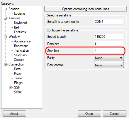
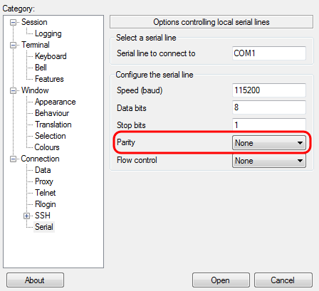
Step 9. In the Parity drop-down menu, select the method of detecting errors in transmission. The recommended method for detecting errors in transmission is None.
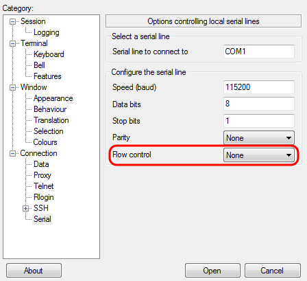
Step 10. In the Flow Control drop-down menu, select the method of preventing data overflow. The recommended method for preventing data overflow is None.
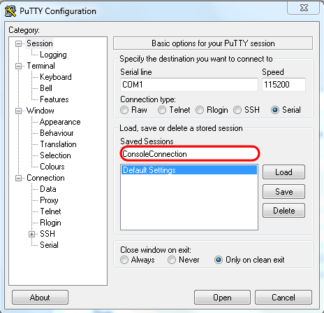
Step 11. (Optional) In order to save the connection settings for future use, go to the Category navigation pane and choose Session. If you do not wish to save the connection settings, skip to Step 14.
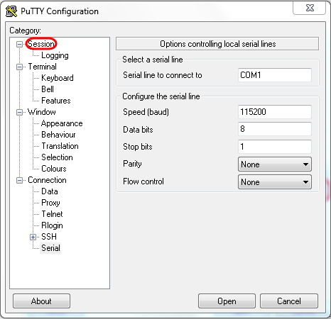
Step 12. Under the Saves Sessions field, enter a name for the settings to be saved as.
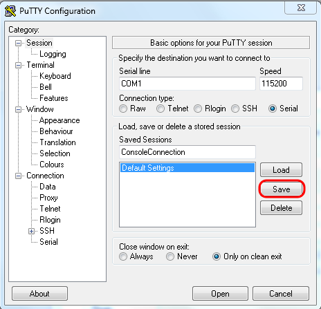
Step 13. Click Save.
Step 14. Click Open.
The COM1 – PuTTY console window opens.
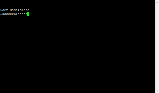
Step 15. Hit Enter on the keyboard to activate the Command Line Interface (CLI). The log in prompt is displayed:
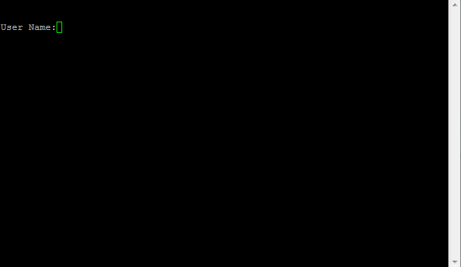
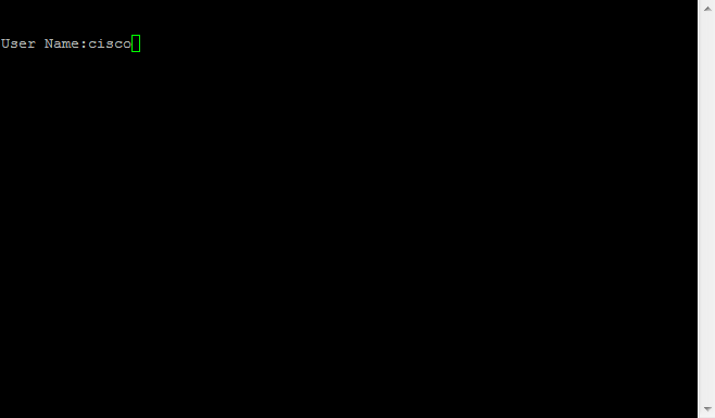
Step 16. Enter the User Name. The default username is cisco.
Step 14. Enter the Password. The default password is cisco.
