Bandwidth Per Port Configuration on Sx500 Series Stackable Switches
Available Languages
Objective
The Bandwidth page allows network managers to define the Ingress Rate Limit and the Egress Shaping Rate. These values determine how much traffic the system can send and receive. The ingress rate limit is the number of bits per second that can be received from the ingress interface. Excess bandwidth above this limit is discarded. Ingress traffic is traffic that originates from outside of the network and flows into the network. Egress traffic is network traffic that originates inside of the network and flows out of the network.
This article explains how to configure bandwidth limitations per interface on the Sx500 Series Stackable Switches.
Applicable Devices
• Sx500 Series Stackable Switches
Software Version
• v1.2.7.76
Bandwidth Configuration on Interfaces
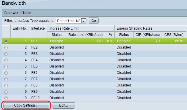
Step 1. Log into the web configuration utility, and choose Quality of Service > General > Bandwidth. The Bandwidth page opens:

Step 2. Choose the interface type from the Interface Type drop-down list in the Filter field and click Go.

Step 3. Click the radio button next to the desired interface and click Edit. The Edit window opens

Step 4. (Optional) Click a radio button for either Unit/Slot and Port or LAG, and choose the interface from the drop-down lists.

Step 5. (Optional) To enable an ingress limit, check the Ingress Rate Limit check box. This is the to limit the ingress (incoming) traffic on the particular port.
Note: If you do not want to configure an Ingress Rate Limit, skip to Step 7.

Step 6. Enter the maximum amount of bandwidth allowed on the interface in the Ingress Rate Limit field. This is the maximum bandwidth of ingress traffic for a specific port.
Note: The Ingress Rate Limit fields do not appear when the interface type is LAG.

Step 7. (Optional) To enable egress shaping on the interface, check the Egress Shaping Rate check box. Egress shaping is useful for when a destination expects a smooth flow of data as opposed to irregular bursts of data.
Note: If you do not want to configure an Egress Rate Limit, skip to Step 10.

Step 8. Enter the maximum bandwidth allowed for the egress interface in the Committed Information Rate (CIR) field. This is the allowable bandwidth which the Internet Service Provider (ISP) provides.

Step 9. Enter the maximum burst size of data allowed by the egress interface (in bytes of data) in the Committed Burst Size field.
Note: This amount can be sent even if it increases the bandwidth above the allowed limit. This is the allowable rate which can exceed the CIR.

Step 10. Click Apply. The Bandwidth configuration is applied.


Step 11. (Optional) Click the radio button next to the desired interface/port and click Copy Settings. The Copy Settings window appears.

Step 12. (Optional) Enter the interface(s) to which the configuration needs to be copied in the provided field.

Step 13. Click Apply to apply the settings.

Revision History
| Revision | Publish Date | Comments |
|---|---|---|
1.0 |
11-Dec-2018 |
Initial Release |
 Feedback