Rapid Spanning Tree Protocol (RSTP) Interface Settings Configuration on Sx500 Series Stackable Switches
Available Languages
Objective
This article explains how to configure RSTP Interface Settings on the Sx500 Series Stackable Switches.
Introduction
Spanning Tree Protocol (STP) is a network protocol that prevents loops from occurring in the network topology. These loops cause switches to forward traffic an infinite amount of times. This causes the network to flood and use its resources which reduces network efficiency.
Rapid Spanning Tree Protocol (RSTP) is an enhancement of STP. RSTP provides a faster STP convergence after a topology change. STP can take 30 to 50 seconds to respond to a topology change while RSTP can respond to a change in 6 seconds.
If you prefer to set up STP, follow the steps in Spanning Tree Protocol (STP) Configuration on Sx500 Series Stackable Switches
Applicable Devices
• Sx500 Series Stackable Switches
Enable Rapid Spanning Tree Protocol
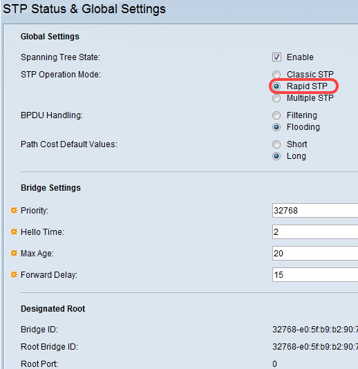
Step 1. Log in to the web configuration utility and choose Spanning Tree > STP Status & Global Settings. The STP Status & Global Settings page opens. Under STP Operation Mode, select the Rapid STP radio button.
RSTP Interface Settings
Step 1. Log in to the web configuration utility and choose Spanning Tree > RSTP Interface Settings. The RSTP Interface Settings page opens. (Optional) Click the port or LAG that you want to test and click Activate Protocol Migration to run a protocol migration test. This test discovers if the link partner (the connected device) that uses STP still exists. If so, the test determines whether the link partner has migrated to RSTP or MSTP. If the link partner still uses an STP link, the devices continue to communicate through the use of STP. If the link partner has been migrated to RSTP, the device communicates through the use of RSTP. If the link partner has been migrated to MSTP, the device communicates through the use of MSTP.


Step 2. Click the radio button of the port or LAG you want to modify and click Edit.

Step 3. (Optional) Click the radio button that corresponds to the desired interface to configure in the Interface field.
• Port — From the Unit/Slot and Port drop-down lists choose the port to configure. This will only affect the single port chosen.
• Lag — From the LAG drop down list; choose the LAG to configure. This will affect the group of ports defined in the LAG configuration.

Step 4. Click the radio button that corresponds to the desired point to point link status in the Point to Point Administrative Status field.
• Enable — The port is considered an RSTP edge port. The port will go to a forwarding mode immediately.
• Disable — Point to point link status is disabled. The port will work at the regular STP convergence speed (30 to 50 seconds) as opposed to the faster RSTP convergence speed (6 seconds).
• Auto — Automatically determines the point to point link status through the use of RSTP Bridge Protocol Data Units (BPDUs).
The following fields display statistics of the interface:
• Point to Point Operational Status — The administrative status if the Point to Point Administrative Status field is set to Auto.
• Role — The role of the port that was assigned by STP to provide STP paths.
– Root – The port is the lowest cost path to forward packets to the root bridge.
– Designated – The port is the interface through which the bridge is connected to the LAN. This role provides the lowest cost path from the LAN to the Root Bridge.
– Alternate – The port provides an alternate path to the root bridge from the root interface.
– Backup – The port provides a back up path to the designated port path toward the spanning tree. This is due to a configuration in which two ports are connected in a loop by a point to point link. Backup ports are also used when a LAN has two or more connections to a shared segment.
– Disabled – The port is not part of the spanning tree.
• Mode — The current spanning tree model of the port (STP or RSTP).
• Fast Link Operational Status — The status of fast link.
– Enabled – Fast Link is enabled.
– Disabled – Fast Link is disabled.
– Automatic – Fast Link is enabled a few seconds after the interface becomes active.
• Port Status — Current state of the specified port.
– Disabled – STP is disabled on the port. The port forwards traffic and learns MAC addresses.
– Blocking – The port is blocked. The port cannot forward traffic or learn MAC addresses. The port can forward BPDU data.
– Listening – The port cannot forward traffic and cannot learn MAC addresses.
– Learning – The port cannot forward traffic but it can learn new MAC addresses.
– Forwarding – The port can forward traffic and can learn new MAC addresses.

Step 5. Click Apply.
Conclusion
You now have RSTP Interface Settings configured on your Sx500 Series Stackable Switch.
Here are some related articles you might find useful:
- Rapid Spanning Tree Protocol (RSTP) Configuration on the 200/300 Series Managed Switches
- Understanding Rapid Spanning Tree Protocol (802.1w)
Revision History
| Revision | Publish Date | Comments |
|---|---|---|
1.0 |
13-Dec-2018 |
Initial Release |
 Feedback