Configure Attendant Console Key LED Pattern on SPA500S with the Help of SPA500 Series IP Phones
Available Languages
Objective
Attendant console key LED is a feature of attendant consoles of the SPA500 series IP phone. It helps users to differentiate between general and work status with visual indication. Console key LED is configured when you enter some specific letters or color patterns to indicate the visual status of the console. The LED pattern indicates the color and blinking patterns for the Attendant Console Keys of the SPA500S.
The objective of this document is to show you how to configure the Attendant Console Key LED settings on the SPA500 Series IP phone.
Note: The SPA500DS will not work with UC500 series unified communication devices and will only work with UC320 unified communication devices.
Applicable Devices
• SPA500 Series IP Phone
• SPA500S Att. Console
Software Version
• v8.6.0 [ UC540 ]
• v3.2(1) [ Cisco Configuration Assistant ]
• v7-5-2a [SPA 525G IP Phone]
LED Script
The LED Script provides information about the color and blinking pattern of the Line Key LED.
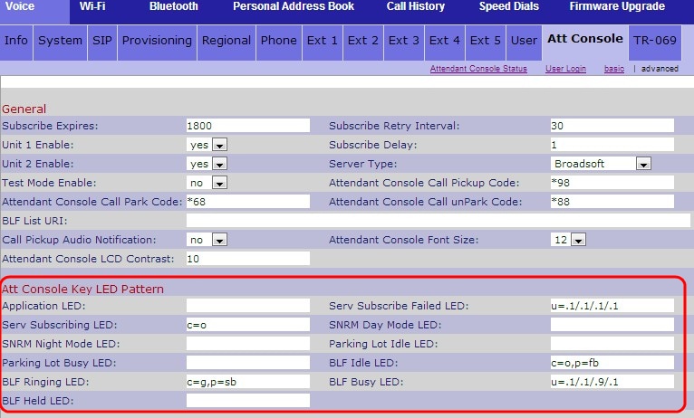
• The format of the script for color is c = o | r | g where:
– o — Represent that the LED color option is turned off.
– r — Represents the red color.
– g — Represents the green color.
• The format of the script for blinking pattern is p = nb | sb | fb | ud where:
– nb — Represents that no blink occurs.
– sb — Represents the slow blink. ( 1s ON and 1s OFF)
– fb — Represents the fast blink. (100ms ON and 100ms OFF)
– ud — Represents the user-defined blinking pattern.
The format for user-defined blinking pattern is u = on / off / on / off where each value is in seconds.
Configuration Attendant Console Key LED Pattern With Web Interface
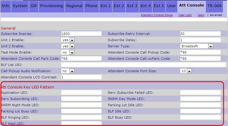
Step 1. Log in to the web configuration utility and choose Admin Login > Advanced > Attendant Console > Att Console Key LED Pattern.

Below are the descriptions for various fields of the Line Key LED Pattern area.

• Application LED — Represents the LED function.
• Serv Subscribe Failed LED — Represents that the subscription for the Att Console is failed. The blank field represents that the default color is green.
• Serv Subscribing LED — Represents that a subscription for the Att Console is in process. The blank field represents that the default color is red.
• SNRM Day Mode LED — Represents that the IP phone is in day mode. The blank field represents that the default color is green.
• SNRM Night Mode LED — Represents that the IP phone is in night mode. The blank field represents that the default color is red.
• Parking Lot Idle LED — Represents that no call is parked and the line is idle. The blank field represents that the default color is red.
• Parking Lot Busy LED — Represents that a call is already parked and the line is busy. The blank field represents that the default color is red.
• BLF Idle LED — Represents that the other extension line which is connected to the IP phone is idle. The blank field represents that the default color is red.
• BLF Ringing LED — Represents that the other extension line which is connected to the IP phone is ringing. The blank field represents that the default color is red.
• BLF Busy LED — Represents that the other extension line which is connected to the IP phone is busy. The blank field represents that the default color is red.
• BLF Held LED — Represents that the other extension which is connected to the IP phone is on hold. The blank field represents that the default color is red.
Step 2. Click Submit All Changes to save the settings.
Revision History
| Revision | Publish Date | Comments |
|---|---|---|
1.0 |
11-Dec-2018
|
Initial Release |
 Feedback