Add a Wireless Network to an Existing Wired Network using a Wireless Access Point (WAP)
Available Languages
Objective
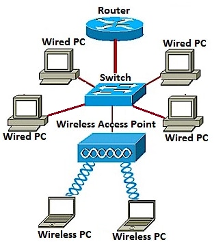
A Wireless Access Point (WAP) is a networking device that allows wireless-capable devices to connect to a wired network. Adding a WAP to your existing wired network is useful to accommodate those devices that are only capable of wireless connection. It is like creating another network only for wireless devices but still be a part of your existing wired network such as shown in the diagram below.
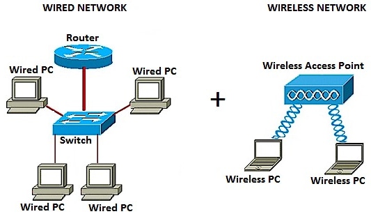
In the network diagram above, the left portion shows an existing wired network. It consists of four wired computers connected to a switch, which is connected to a router. In the right portion, a wireless network shows two wireless computers connected to a WAP.
The objective of this article is to show you how to add a wireless network to your existing wired network using a wireless access point.
Applicable Devices
- WAP100 Series
- WAP300 Series
- WAP500 Series
Software Version
- 1.0.6.5 — WAP121, WAP321
- 1.0.2.8 — WAP131, WAP351
- 1.0.1.7 — WAP150, WAP361
- 1.3.0.3 — WAP371
- 1.2.1.3 — WAP551, WAP561
- 1.0.0.17 — WAP571, WAP571E
Add a Wireless Network to an Existing Wired Network
Set up the Wireless Network
Note: Images may vary depending on the exact model of your WAP. The images used in this article are taken from the WAP361.
Step 1. Connect the WAP to your router or switch using the supplied Ethernet cable.
Note: If your WAP does not have Power over Ethernet (PoE) capability, connect the AC power adapter to the WAP and plug it to the power outlet.
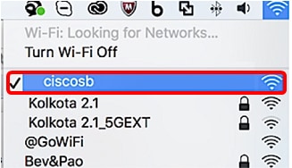
Step 2. Connect your wireless computer to the wireless network that the WAP is broadcasting.
Note: The default Service Set Identifier (SSID) or wireless network name of the Cisco Access Point is ciscosb.
Step 3. On the wireless computer, access the web-based utility of the WAP by launching a web browser and entering the IP address of the WAP in the address bar.
Note: In the event that you do not know the IP address of your WAP, you can use the Cisco FindIT Discovery Tool or the Cisco FindIT Network Management tool if these applications are installed in your network. These applications will help you check the IP addresses and other information of the access point and other Cisco devices within your network. To learn more, click here.

Note: In the image above, 192.168.1.245 is used as an example of the IP address. This is the default IP address of Cisco Access Points.
Step 4. In the authentication window, enter the username and password of the WAP in the Username and Password fields, respectively.
Note: You can set up to five users to each access point that you are going to add to the network. These users are the ones authorized to access the web-based utility through their authentication keys but only one of these users can have the Read/Write privilege level. Also, you can create a different username and password to each user. To learn how, click here.

Note: The default username and password of the default user for Cisco Access Points is cisco/cisco.
Step 5. Click Log In.

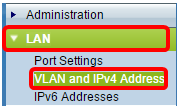
Step 6. In the navigation area, choose LAN > IPv4 Setting.
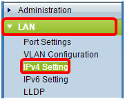
Note: If you are using the WAP121, WAP321, WAP371, WAP551, or the WAP561, choose LAN > VLAN and IPv4 Address.
Note: If you want to use IPv6 Addressing instead, click here for instructions.
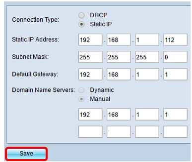
Step 7. Click a radio button to choose the Connection Type.
- DHCP — The access point acquires its IP address from a Dynamic Host Configuration Protocol (DHCP) server on the network.
- Static IP— You will be the one to manually assign the IPv4 address to the WAP.

Note: In this example, DHCP is chosen. This is the default setting. If you performed this step, skip to Step 12.
Step 8. (Optional) If you chose Static IP in the previous step, enter the static IP address you want to assign to the WAP in the Static IP Address field. Make sure that the IP address you assign is in the same range as your network.

Note: In this example, the IP address used is 192.168.1.112.
Step 9. (Optional) Enter the subnet mask in the Subnet Mask field.

Note: In this example, 255.255.255.0 is used.
Step 10. Enter the router IP address in the Default Gateway field.

Note: In this example, 192.168.1.1 is used as the default gateway.
Step 11. In the Domain Name Servers (DNS) area, the radio button for Manual will be automatically selected once the Connection Type is set to Static IP. You can enter up to two DNS addresses in the fields provided.

Note: In this example, 192.168.1.1 is used.
Step 12. Click Save.
Configure Wireless Settings
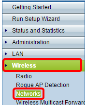
Step 1. Choose Wireless > Networks.
Step 2. (Optional) If you are using a dual-band access point, click a radio button to choose the Radio Interface that you want to configure.
- Radio 1 (2.4 GHz) — For wireless clients that operate in the 2.4 GHz frequency.
- Radio 2 (5 GHz) — For wireless clients that operate in the 5 GHz frequency.

Note: In this example, Radio 1 (2.4 GHz) is chosen.
Step 3. Under the Virtual Access Points (SSIDs) area, check the box beside the default Virtual Access Point (VAP) and click the Edit button below it.
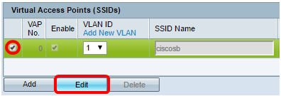
Note: You can add or create multiple VAPs on your WAP depending on the exact model of your device by clicking on the Add button. For the WAP361, seven additional VAPs can be created.
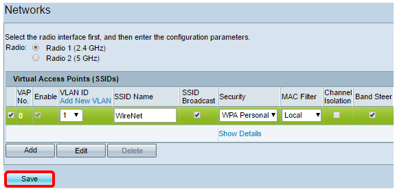
Step 4. Under SSID Name, create a new name for your wireless network in the field provided.

Note: In this example, WireNet is used.
Step 5. (Optional) Under SSID Broadcast, check or uncheck the box depending on your preference. Checking the box would allow your wireless network to broadcast its SSID or to be visible to all wireless devices within its range. Unchecking the box would hide it from all wireless devices.

Note: In this example, SSID broadcast is checked.
Step 6. Under Security, click on the drop-down menu to choose the type of security you want to set up on the wireless network. The options are:
- None – This option would set the security to open and allow all wireless devices to connect to your wireless network without being asked for a password or authentication.
- WPA Personal — Wi-Fi Protected Access (WPA) is a security protocol designed to improve upon the security features of Wired Equivalent Privacy (WEP). WPA uses higher, 256-bit keys and improves data encryption and user authentication. This security mode allows you to use either the Temporal Key Integrity Protocol (TKIP) algorithm, or the latest, higher-level Advanced Encryption Security (AES) algorithm if the device is newer and supports it with WPA. Both options, however, implement stronger security standards.
- WPA Enterprise — In Enterprise mode, Wi-Fi Protected Access (WPA) is used with Remote Authentication Dial-In User Service (RADIUS) server authentication.

Note: In this example, WPA Personal is chosen. The Security details window would then be visible.
Step 7. Choose the types of client stations that you want to support by checking the check boxes in the WPA Versions area.
- WPA-TKIP — This option would allow wireless clients that only support the original WPA and TKIP security protocol to be able to connect to the network.
- WPA2-AES — This WPA version provides the best security per IEEE 802.11i standard. As per the latest Wi-Fi Alliance requirement, the WAP has to support this mode all the time.
Note: If the network has a mix of clients, check both of the check boxes. This setting lets both WPA and WPA2 client stations associate and authenticate, but it uses the more robust WPA2 for clients who support it. This WPA configuration allows more interoperability in place of some security.

Step 8. In the Key field, enter a password consisting of 8 to 63 characters. Each wireless device that would try to connect to this wireless network will be asked for this authentication key.

Step 9. (Optional) Check the Show Key as Clear Text box to show the password you created.

Note: The Key Strength Meter area shows colored bars based on the strength of the key that you have created. In this example, Str0ngPassw0rd! is used as the authentication key.
Step 10. In the Broadcast Key Refresh Rate field, enter a value from 0 to 86400 seconds. This is the interval at which the broadcast (group) key is refreshed for clients associated with this VAP.

Note: In this example, 300 seconds is used. This is the default value.
Step 11. (Optional) Under MAC Filter, click on the drop-down list either to disable MAC Filter or to specify whether the stations that can access this VAP are restricted to a configured global list of MAC addresses. The options are:
- Disabled — Does not use MAC filtering.
- Local — Uses the MAC authentication list that you configure on the MAC Filtering page.
- RADIUS — Uses the MAC authentication list on an external RADIUS server.
Note: To learn how to configure MAC Filtering, click here.

Note: In this example, Local is chosen.
Step 12. (Optional) Check or uncheck the check box under Channel Isolation to enable or disable it depending on your preference. When enabled, the WAP blocks communication between the wireless clients on the same VAP. The WAP still allows data traffic between its wireless clients and the wired devices on the network, across a Wireless Distribution System (WDS) link, and with other wireless clients associated with a different VAP, but not among the wireless clients. When disabled, the wireless clients can communicate with one another normally by sending traffic through the WAP.

Note: In this example, Channel Isolation is disabled. This is the default setting.
Step 13. (Optional) Check or uncheck the check box under Band Steer to enable or disable it depending on your preference. This feature is for dual-band WAPs only. Enabling band steer effectively utilizes the 5 GHz band by steering dual-band supported clients from the 2.4 GHz band to the 5 GHz band when both radios are up.

Note: In this example, Band Steer is enabled.
Step 14. Click Save.
You should now have successfully added a wireless network to your existing wired network using a wireless access point as shown in the diagram below.
Revision History
| Revision | Publish Date | Comments |
|---|---|---|
1.0 |
13-Dec-2018 |
Initial Release |
 Feedback