Configure Wireless Radio Settings on the WAP551 or WAP561 Access Point
Available Languages
Objective
The radio is the physical component of the Wireless Access Point (WAP) that creates a wireless network. The radio settings on the WAP control the behavior of the radio and determine the signals the device transmits. Changing the frequency of the WAP is useful in preventing the WAP from interfering and receiving interference from other wireless signals. In many cases, there’s a need for the settings of the WAP to be the same with the settings of the wireless router, as well as other access points in the network, for seamless wireless connectivity. Check the wireless settings of the wireless router before deploying the wireless access point.
This article aims to show the steps on how to configure the basic radio settings on the WAP551 or WAP561 access point.
Applicable Devices
- WAP551
- WAP561
Software Version
- 1.0.4.4 — WAP551, WAP561
Configure Wireless Radio Settings
Step 1. Log in to the web-based utility of the access point and choose Wireless > Radio.

Step 2 In the TSPEC Violation Interval field, enter the time interval (in seconds) that the WAP needs to wait before it reports the associated clients that do not adhere to mandatory admission control procedures. The value can be 0 to 900 seconds, where 0 means disabled. The default value is 300.
Note: In this example, 500 is entered.

Step 3. In the Radio Setting Per Interface area, click the radio button that corresponds to the Radio Frequency that needs to be configured.
Note: This feature is only available on the WAP561. In this example, Radio 1 is chosen.

Step 4. In the Basic Settings area, check the Enable check box to activate the radio interface. This is not checked by default.
Note: The MAC Address show is the MAC address of the radio interface.

Step 5. Choose the desired radio mode from the Mode drop-down list. The options are:
- 802.11a — This option only allows devices that support Wireless-A to connect to the WAP. The wireless devices get a maximum of 54 Mbps bandwidth when this mode is chosen.
- 802.11b/g — This option only allows devices that support Wireless-G and Wireless-B to connect to the WAP. Wireless-B devices get a maximum of 11 Mbps bandwidth, while Wireless-G devices get a maximum of 54 Mbps. This option operates in the 2.4 GHz frequency.
- 802.11a/n — This option only allows devices that support Wireless-A and Wireless-N to connect to the WAP. It operates on the 5 GHz frequency, and can handle up to 150 Mbps bandwidth.
- 802.11b/g/n — This option only allows devices that support Wireless B, G and N to connect to the WAP.
- 5 GHz 802.11n — This option only allows devices that support Wireless-N operating in the 5GHz frequency to connect to the WAP. For best results, use a Wireless-N adapter on your computer if it is not yet equipped with one.
- 2.4 GHz 802.11n — This option only allows devices that support Wireless-N operating in the 2.4 GHz frequency to connect to the WAP.
Note: In this example, 2.4 GHz 802.11n is chosen.

Step 6. Choose the channel bandwidth for the radio from the Channel Bandwidth drop-down list. The options are:
- 20 MHz — This option limits the use of channel to a 20 MHz channel.
- 20/40 MHz — This option consists of two 20 MHz channels that are contiguous in the frequency domain.
Note: In this example, 20 MHz is chosen.

Step 7. From the Primary Channel drop-down list, choose a channel to set as primary. The primary channel is used for devices that only support 20/40 MHz channels. The options are:
- Upper — This option sets the upper 20 MHz channel as the primary channel.
- Lower — This option sets the lower 20 MHz channel as the primary channel.
Note: In this example, the Primary Channel is automatically set to Lower since Channel Bandwidth is set to 20 MHz.

Note: The Primary Channel drop-down list is automatically disabled if the Channel Bandwidth is set to 20 MHz.
Step 8. Choose the range of the radio spectrum that the radio uses to transmit and receive from the Channel drop-down list. If Auto is chosen, the WAP scans available channels and chooses a channel where the least traffic is detected.

Step 9. Click Save to retain the settings.

You should now have configured the basic wireless settings of your wireless access point.
Configure Advanced Radio Settings
Step 1. Choose an option form the Short Guard Interval Supported drop-down list. This is the interval between symbol transmissions. It prevents Inter-Symbol and Inter-Carrier Interference (ISI,ICI). The short guard interval can be shortened to increase throughput by up to 10 percent. The options are:
- Yes — This option lets the WAP transmit data at a guard interval of 400 nanoseconds when communicating with clients.
- No — This option lets the WAP transmit data at a guard interval of 800 nanoseconds.
Note: In this example, Yes is chosen.

Step 2. Choose a protection setting from the Protection drop-down list. The options are:
- Auto — This option prevents interference when legacy devices are within the range of the WAP.
- Off — This option disables the feature, leaving the wireless clients vulnerable to 802.11n interference.
Note: In this example, Auto is chosen.

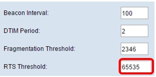
Step 3. In the Beacon Interval field, enter the interval between beacon transmissions. Beacon fames are transmitted periodically to announce the presence of a wireless network. The interval is measured in milliseconds.
Note: In this example, Beacon Interval is 100.

Step 4. In the DTIM Period field, enter a number for 1 to 255 for the Delivery Traffic Information Map (DTIM) period. The DTIM message is an element included in some Beacon frames. It indicates which client stations, currently sleeping in low-power mode, have data buffered on the WAP device awaiting pickup. The value you will enter indicates how often the clients served by this WAP device should check for buffered data still on the WAP device awaiting pickup.

Note: In this example, the DTIM Period used is 2.
Step 5. In the Fragmentation Threshold field, enter the maximum size of packets in bytes that can be transmitted over the network. Packets larger than the maximum size are fragmented and set as several smaller packets. Fragmentation is not recommended unless your experience radio interference.
Note: The default value is 2346.

Step 6. In the RTS Threshold field, enter the Request to Send (RTS) threshold value which indicates the number of octets in a MAC Protocol Data Unit (MPDU), which an RTC/CTS handshake is not performed. A low threshold value sends packets more frequently which consume more bandwidth.
Note: The default value is 65535.

Step 7. In the Maximum Associated Clients field, enter the maximum number of devices allowed to connect to the WAP at any given time.
Note: The default value is 200.

Step 8. Choose the percentage value of the transmit power level from the Transmit Power drop-down list.
Note: The default value is Full-100%

Step 9. Choose the frame burst support setting from the Frame-burst Support drop-down list. Frame burst support is typically enabled to improve radio performance in the downstream direction. The options are:
- Off – This option means that frame burst support is disabled.
- On – This option means that frame burst support is enabled.
Note: In this example, On is chosen.

Step 10. Choose the multicast traffic transmission rate setting from the Fixed Multicast Rate drop-down list. The default value is Auto.

Step 11. Check the desired transmission rate check boxes in the Legacy Rate Sets table. Multiple rates can be checked.

Step 12. (Optional) Check the Broadcast/Multicast Rate Limiting check box and then enter the following information in the Rate Limit and Rate Limit Burst fields:
- Rate Limit — Enter the rate limit of multicast and broadcast traffic in packets per second.
- Rate Limit Burst — Enter the limit of traffic that can be sent in a burst in packets per second.
Note: In this example, Rate Limit is 50, and Rate Limit Burst is 75.

Step 13. Choose the traffic specification (TSPEC) mode from the TSPEC Mode drop-down list. The options are:
- On — Enable TSPEC on the WAP. TSPEC is sent from a Quality of Service (QoS) capable client and requests a certain amount of network traffic from the WAP. It is useful when you have devices in the network that support QoS.
- Off — TSPEC is not enabled on the WAP.
Note: In this example, TSPEC Mode is Off.

Step 14. Choose a mode that regulates the admission control mandatory (ACM) for the voice access category from the TSPEC Voice ACM Mode drop-down list.
- On — This option lets a station send a TSPEC request for bandwidth to the WAP before it can send or receive a voice traffic stream.
- Off — This option lets a station send and receive voice traffic without a TSPEC request.
Note: In this example, TSPEC Voice ACM Mode is Off.

Step 15. Enter the maximum amount of traffic the WAP tries to transmit wirelessly with a voice admission control to gain access in the TSPEC Voice ACM Limit field.
Note: In this example, TSPEC Voice ACM Limit is 20.

Step 16. Choose a mode that regulates the ACM for the video access category from the TSPEC Voice ACM Mode drop-down list. The options are:
- On — This option would require a station to send a TSPEC request for bandwidth to the WAP before it can send or receive video traffic.
- Off — This option would allow sending and receiving voice traffic without a TSPEC request.
Note: In this example, TSPEC Video ACM Mode is Off.

Step 17. Enter the maximum amount of traffic that the WAP tries to transmit wirelessly with a video admission control to gain access in the TSPEC Video ACM Limit field.
Note: In this example, the TSPEC Video ACM Limit is 15.

Step 18. Enter the amount of time in second for the WAP to detect a downlink traffic speculation as idle before the WAP deletes it in the TSPEC AP Inactivity Timeout field.
Note: In this example, the TSPEC AP Inactivity Timeout is 30.

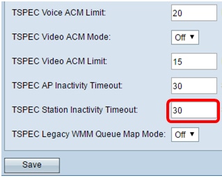
Step 19. Enter the amount of time in seconds for the WAP to detect an uplink traffic speculation as idle before the WAP deletes it in the TSPEC Station Inactivity Timeout field.
Note: In this example, TSPEC Station Inactivity Timeout is 30.

Step 20. Choose the desired mode from the TSPEC Legacy WMM Queue Map Mode drop-down list.
- On — This option lets legacy traffic to mix with queues that operate as ACM.
- Off — This option disables intermixed legacy traffic on queues that operate as ACM.
Note: In this example, Off is chosen.

Step 21. Click Save to retain the settings.

You should now have configured the advanced wireless settings of your wireless access point.
Revision History
| Revision | Publish Date | Comments |
|---|---|---|
1.0 |
12-Dec-2018 |
Initial Release |
 Feedback