Initial Configuration of the WAP150, WAP351, WAP361, and WAP371 Wireless Access Points Using the Setup Wizard
Available Languages
Objective
The Setup Wizard is a built-in feature that is used to help with the initial configuration of the Wireless Access Points (WAPs). It makes the configuration of basic settings easy. The step-by-step process of the Setup Wizard guides you through the initial setup of the WAP device, and provides a quick way to get the basic features of the WAP functional.
The objective of this document is to show you how to configure the WAP150, WAP351, WAP361, and WAP371 Wireless Access Points using the Setup Wizard.
Applicable Devices
- WAP150
- WAP351
- WAP361
- WAP371
Software Version
- 1.0.1.7 – WAP150, WAP361
- 1.0.2.8 – WAP351
- 1.3.0.3 – WAP371
Configuration
Note: The images used below are taken from WAP361.
Step 1. Log in to the access point web-based utility. Under the Getting Started menu page, click Run Setup Wizard.
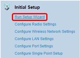
Note: If this is the first time you have logged in to the WAP, the Setup Wizard will open automatically.
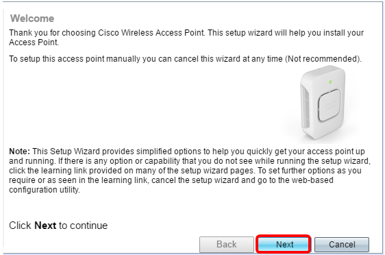
Step 2. Click Next on the Welcome page of the Access Point Setup Wizard to continue.
Step 3. Click the radio button that corresponds to the method you want to use to determine the IP address of the WAP.
The options are defined as follows:
- Dynamic IP Address (DHCP) (Recommended) — Allows the DHCP server to assign a dynamic IP address for the WAP. If you choose this, click Next then skip to Step 9.
- Static IP Address — Allows you to create a fixed (static) IP address for the WAP. A static IP address does not change.
Note: In this example, Dynamic IP Address (DHCP) is chosen.
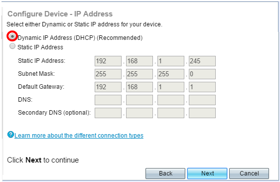
Step 4. If Static IP Address was chosen in the previous step, enter the IP address of the WAP in the Static IP Address field. This IP address is unique to the WAP and should not be used by another device in the network.
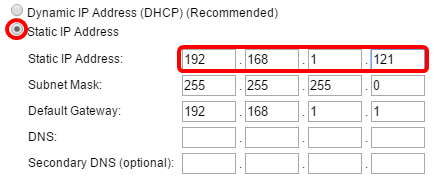
Note: In this example, 192.168.1.121 is used as the Static IP Address.
Step 5. Enter the subnet mask in the Subnet Mask field.
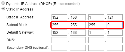
Note: In this example, 255.255.255.0 is used as the Subnet Mask.
Step 6. Enter the default gateway for the WAP in the Default Gateway field. This is the private IP address of your router.
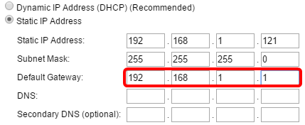
Note: In this example, 192.168.1.1 is used as the Default Gateway.
Step 7. (Optional) If you want to access the web-based utility outside of your network, enter primary Domain Name System (DNS) address in the DNS field. Your Internet Service Provider (ISP) should provide the DNS server address to you.
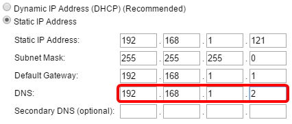
Note: In this example, 192.168.1.2 is used as the DNS address.
Step 8. (Optional) Enter a secondary DNS address in the Secondary DNS fields then click Next.
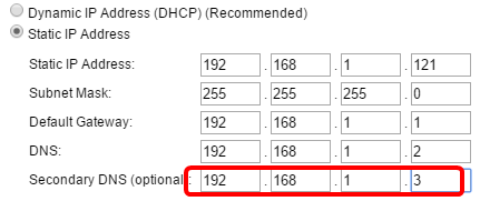
Note: In this example, 192.168.1.3 is used as the Secondary DNS address.
Single Point Setup
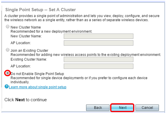
Step 9. In the Single Point Setup – Set A Cluster screen, select a radio button that corresponds to how you want to configure the cluster settings of the WAP. Clustering allows you to manage multiple access points from a single point, instead of going to each device and changing the settings individually.
The options are defined as follows:
- New Cluster Name — Select this option if you want to create a new cluster.
Note: For WAP351 and WAP371, the option is Create a New Cluster.
- Join an Existing Cluster — Select this option if you want the WAP to join an existing cluster. If you choose this option, skip to Step 11.
- Do not Enable Single Point Setup — Choose this option if you do not want the WAP to be part of a cluster. If you choose this option, click Next then skip to Step 13.
Note: In this example, Do not Enable Single Point Setup is chosen.
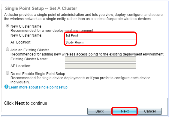
Step 10. If you chose New Cluster Name in the previous step, enter the name of the new cluster and its location in the New Cluster Name and AP Location fields, respectively then click Next. The AP Location is the physical location of the access point defined by the user (e.g. Office). Go to Step 13.
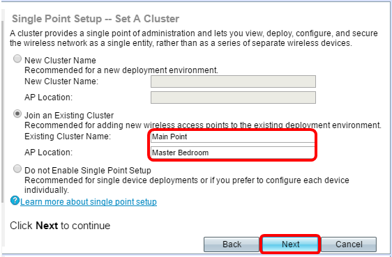
Step 11. If you chose Join an Existing Cluster in Step 9, enter the name of the cluster and its location in the Existing Cluster Name and AP Location fields, respectively then click Next.
Note: This option is ideal if there is already an existing wireless network and all settings have already been configured.
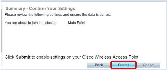
Step 12. Review your settings to make sure the data is correct then click Submit.
Time Settings
Step 13. Choose your time zone from the Time Zone drop-down list.
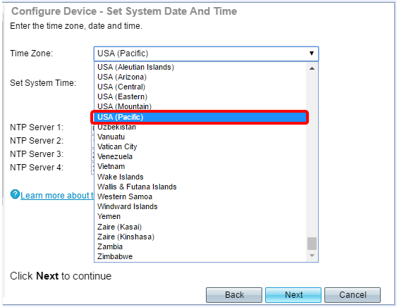
Note: In this example, USA (Pacific) is chosen.
Step 14. Click the radio button that corresponds to the method you wish to use to set the time of the WAP.
The options are as follows:
- Network Time Protocol (NTP) — The WAP gets the time from an NTP server.
- Manually — The time is manually entered into the WAP. If this option is chosen, skip to Step 16.
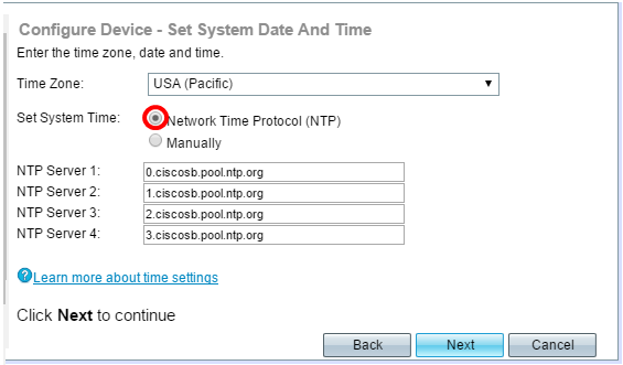
Note: In this example, Network Time Protocol (NTP) is used.
Step 15. Enter the domain name of the NTP server that provides the date and time in the NTP Server 1 field. You can add up to four different NTP servers by entering them in their respective fields and then click Next. Then, skip to Step 17.
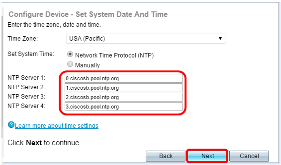
Note: In this example, there are four NTP Servers entered.
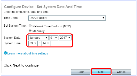
Step 16. (Optional) If you chose Manually in Step 14, select the date in the System Date drop-down lists to choose the month, day, and year respectively. Select the hour and minutes from the System Time drop-down lists then click Next.
Device Password
Step 17.In the Configure Device - Set Password screen, enter a new password for the WAP in the New Password field and confirm it. This password is used to gain administrative access to the web-based utility of the WAP itself and not for connecting to the wireless network.

Note: The Password Strength Meter field displays vertical bars that change as you enter the password.
The Password Strength Meter colors are defined as follows:
- Red — The minimum password complexity requirement is not met.
- Orange — The minimum password complexity requirement is met, but the strength of password is weak.
- Green — The minimum password complexity requirement is met, and the strength of password is strong.
Step 18. (Optional) Enable password complexity by checking the Enable Password Complexity check box. This requires that the password is at least 8 characters long and composed of lower and upper case letters and numbers or symbols. Password Complexity is enabled by default.
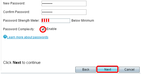
Step 19. Click Next to continue.
Configuring Radios 1 and 2 (2.4 and 5 GHz)
The Wireless network settings must be configured individually for each radio channel. The process for setting up the wireless network is the same for each channel.
Note: For the WAP371, Radio 1 is for the 5 GHz band and Radio 2 is for the 2.4 GHz band.
Step 20. In the Configure Radio 1 - Name Your Wireless Network area, enter a name for the wireless network in the Network Name (SSID) field then click Next.
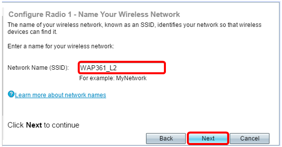
Note: In this example, WAP361_L2 is used as the Network Name.
Step 21. In the Configure Radio 1 - Secure Your Wireless Network area, click the radio button that corresponds with the network security you would like to apply to your wireless network.
The options are defined as follows:
- Best Security (WPA2 Personal - AES) — Provides the best security and is recommended if your wireless devices support this option. WPA2 Personal uses Advanced Encryption Standard (AES) and a Pre-Shared Key (PSK) between the clients and the access point. It uses a new encryption key for each session, which makes it difficult to compromise.
- Better Security (WPA/WPA2 Personal - TKIP/AES) — Provides security when there are older wireless devices that do not support WPA2. WPA Personal uses AES and Temporal Key Integrity Protocol (TKIP). It uses IEEE 802.11i Wi-Fi Standard.
- No Security (Not recommended) — The wireless network does not require a password and can be accessed by anyone. If chosen, a pop-up window will appear asking if you want to disable security; click Yes to continue. If this option is chosen, skip to Step 24.
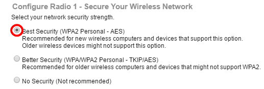
Note: In this example, Best Security (WPA2 Personal -AES) is chosen.
Step 22. Enter the password for your network in the Security Key field. The colored bar to the right of this field shows the complexity of the entered password.
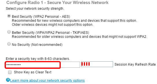
Step 23. (Optional) To see the password as you type, check the Show Key as Clear Text check box then click Next.

Step 24. In the Configure Radio 1 - Assign The VLAN ID For Your Wireless Network area, choose an ID for the network from the VLAN ID drop-down list. If the management VLAN is the same as the VLAN assigned to the wireless network, wireless clients on the network can administer the device. You can also use Access Control Lists (ACL) to disable the administration from wireless clients.
Note: For WAP371 and WAP150, you need to type in the ID in the VLAN ID field provided. The VLAN ID range is from 1-4094.
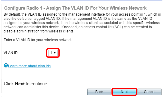
Note: In this example, VLAN ID 1 is used.
Step 25. Click Next to continue with the Setup Wizard to configure Radio 2.
Note: The process for configuring wireless network settings for Radio 2 is the same as that of Radio 1.
Captive Portal
Captive Portal allows you to set up a guest network where wireless users need to be authenticated first before they can have access to the Internet. Follow the steps below to configure Captive Portal.
Step 26. In the Enable Captive Portal - Create Your Guest Network area, choose the Yes radio button then click Next.
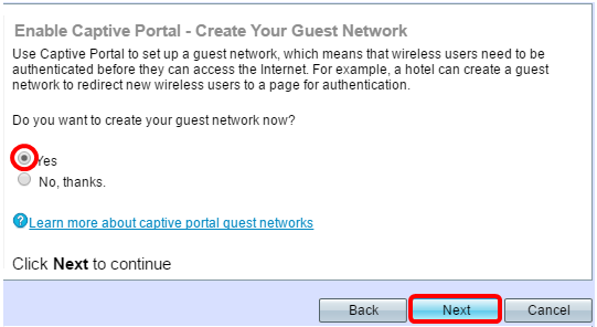
Note: If you prefer not to enable Captive Portal, click No and the Setup wizard will take you to the Summary page. Then, skip to Step 35.
Step 27. Select the desired radio frequency for the guest network. The 2.4 GHz band offers support for legacy devices and can propagate a broader wireless signal across multiple walls. The 5 GHz band, on the other hand, is less crowded and can provide more throughput by taking up a 40 MHz frequency of the band instead of the standard 20 MHz in the 2.4 GHz band. In addition to the shorter range, there are also fewer devices that support the 5 GHz band compared to 2.4 GHz.

Note: In this example, Radio 1 (5 GHz) is chosen.
Step 28. Enter the name of the guest SSID in the Guest Network name field then click Next.
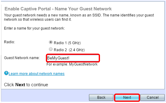
Note: In this example, BeMyGuest! is used as the Guest Network name.
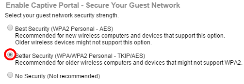
Step 29. Click the radio button that corresponds to the network security you would like to apply to your guest wireless network.
The options are defined as follows:
- Best Security (WPA2 Personal - AES) — Provides the best security and is recommended if your wireless devices support this option. WPA2 Personal uses AES and a Pre-Shared Key (PSK) between the clients and the access point. It uses a new encryption key for each session that makes it difficult to compromise.
- Better Security (WPA Personal - TKIP/AES) — Provides security when there are older wireless devices that do not support WPA2. WPA Personal uses AES and TKIP. It uses IEEE 802.11i Wi-Fi Standard.
- No Security (Not recommended) — The wireless network does not require a password and can be accessed by anyone. If chosen, a pop-up window will appear asking if you want to disable security; click Yes to continue. If this option is chosen, click Next then skip to Step 35.
Note: In this example, Better Security (WPA Personal - TKIP/AES) is chosen.
Step 30. Enter the password for your network in the Security Key field. The colored bar to the right of this field shows the complexity of the entered password.
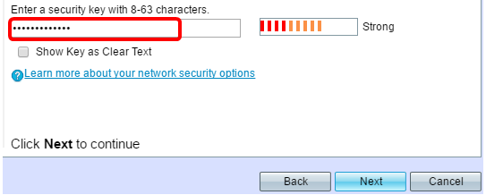
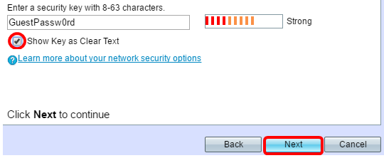
Step 31. (Optional) To see the password as you type, check the Show Key as Clear Text check box then click Next.
Step 32. In theEnable Captive Portal – Assign the VLAN ID area, choose an ID for the guest network from the VLAN ID drop-down list then click Next.
Note: For WAP371 and WAP150, you need to type in the ID in the VLAN ID field provided. The VLAN ID range is from 1-4094.
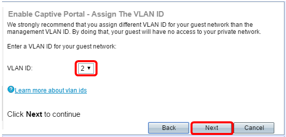
Note: In this example, VLAN ID 2 is chosen.
Step 33. (Optional) If you want new users to be redirected to an alternative startup page, check the Enable Redirect URL check box in the Enable Captive Portal – Enable Redirect URL screen.

Step 34. (Optional) Enter the URL for your redirect URL in the Redirect URL field then click Next.
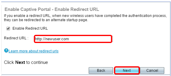
Note: In this example, http://newuser.com is used as the Redirect URL.
Summary
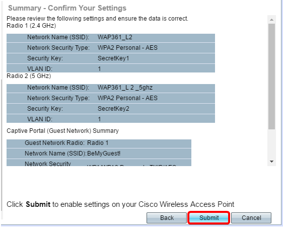
Step 35. Review the settings shown and ensure that the information is correct. If you would like to change a setting, click the Back button until the desired page is reached. Otherwise, click Submit to enable your settings on the WAP.
Step 36. The Device Setup Complete screen will then appear to confirm that your device has been successfully set up. Click Finish.
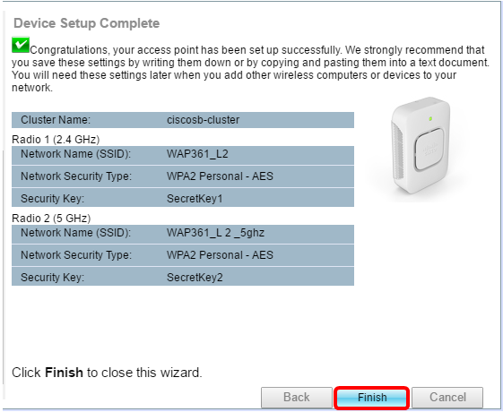
You should now have successfully configured your Wireless Access Point using the Setup Wizard.
Revision History
| Revision | Publish Date | Comments |
|---|---|---|
1.0 |
10-Dec-2018 |
Initial Release |
 Feedback