Configure Intersite L3out With ACI Multi-Site Fabrics
Available Languages
Download Options
Bias-Free Language
The documentation set for this product strives to use bias-free language. For the purposes of this documentation set, bias-free is defined as language that does not imply discrimination based on age, disability, gender, racial identity, ethnic identity, sexual orientation, socioeconomic status, and intersectionality. Exceptions may be present in the documentation due to language that is hardcoded in the user interfaces of the product software, language used based on RFP documentation, or language that is used by a referenced third-party product. Learn more about how Cisco is using Inclusive Language.
Contents
Introduction
This document describes the steps for the intersite L3out configuration with Cisco Application Centric Infrastructure (ACI) multi-site fabric.
Prerequisites
Requirements
Cisco recommends that you have knowledge of these topics:
- Functional ACI multi-site fabric setup
- External router/connectivity
Components Used
The information in this document is based on:
-
Multi-Site Orchestrator (MSO) Version 2.2(1) or later
-
ACI Version 4.2(1) or later
- MSO nodes
- ACI fabrics
- Nexus 9000 Series Switch (N9K) (End Host and L3out external device simulation)
- Nexus 9000 Series Switch (N9K) (Inter-site Network (ISN))
The information in this document was created from the devices in a specific lab environment. All of the devices used in this document started with a cleared (default) configuration. If your network is live, ensure that you understand the potential impact of any command.
Background Information
Supported Schemas for Intersite L3out Configuration
Schema-config1
- Tenant stretched between sites (A and B).
- Virtual Routing and Forwarding (VRF) stretched between sites (A and B).
- Endpoint Group (EPG)/Bridge Domain (BD) local to one site (A).
- L3out local to another site (B).
- External EPG of L3out local to site (B).
- Contract creation and configuration done from MSO.
Schema-config2
- Tenant stretched between sites (A and B).
- VRF stretched between sites (A and B).
- EPG/BD stretched between sites (A and B).
- L3out local to one site (B).
- External EPG of L3out local to site (B).
- Contract configuration can be done from MSO, or each site has local contract creation from Application Policy Infrastructure Controller (APIC) and attached locally between the stretched EPG and L3out external EPG. In this case, shadow External_EPG appears at site-A because it is needed for local contract relation and policy implementations.
Schema-config3
- Tenant stretched between sites (A and B).
- VRF stretched between sites (A and B).
- EPG/BD stretched between sites (A and B).
- L3out local to one site (B).
- External EPG of L3out stretched between sites (A and B).
- Contract configuration can be done from MSO, or each site has local contract creation from APIC and attached locally between the stretched EPG and stretched external EPG.
Schema-config4
- Tenant stretched between sites (A and B).
- VRF stretched between sites (A and B).
- EPG/BD local to one site (A) or EPG/BD local to each site (EPG-A in site A and EPG-B in site B).
- L3out local to one site (B), or for redundancy toward external connectivity you can have L3out local to each site (local to site A and local to site B).
- External EPG of L3out stretched between sites (A and B).
- Contract configuration can be done from MSO or each site has local contract creation from APIC and attached locally between stretched EPG and stretched external EPG.
Schema-config5 (Transit routing)
- Tenant stretched between sites (A and B).
- VRF stretched between sites (A and B).
- L3out local to each site (local to site A and local to site B).
- External EPG of local to each site (A and B).
- Contract configuration can be done from MSO or each site has local contract creation from APIC and attached locally between the external EPG local and shadow external EPG local.
Schema-config5 (InterVRF Transit Routing)
- Tenant stretched between sites (A and B).
- VRF local to each site (A and B).
- L3out local to each site (local to site A and local to site B).
- External EPG of local to each site (A and B).
- Contract configuration can be done from MSO or each site has local contract creation from APIC and attached locally between the external EPG local and shadow external EPG local.
Note: This document provides basic intersite L3out configuration steps and verification. In this example, Schema-config1 is used.
Configure
Network Diagrams
Physical Topology

Logical Topology
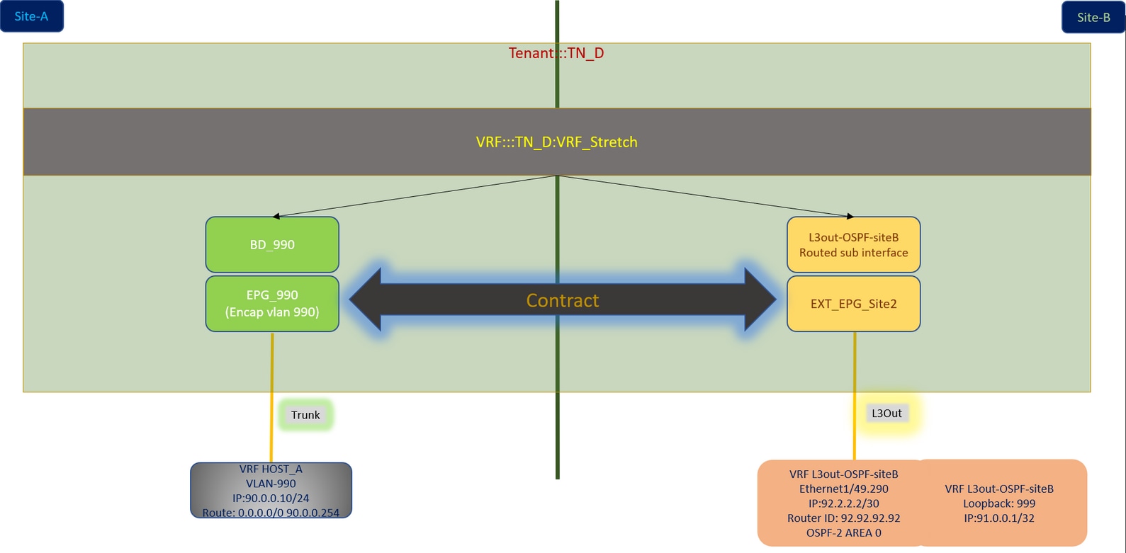
Configurations
In this example, we use Schema-config1. However, this configuration can be completed in a similar way (with minor changes as per contract relation) for other supported schema-configs, except the stretched object needs to be in the stretched template instead of the specific site template.
Configure Schema-config1
- Tenant stretched between sites (A and B).
- VRF stretched between sites (A and B).
- EPG/BD local to one site (A).
- L3out local to another site (B).
- External EPG of L3out local to site (B).
- Contract creation and configurations done from MSO.
Review the Intersite L3Out Guidelines and Limitations.
-
Unsupported configuration with intersite L3out:
-
Multicast receivers in a site that receives multicast from an external source via another site L3out. Multicast received in a site from an external source is never sent to other sites. When a receiver in a site receives multicast from an external source it must be received on a local L3out.
-
An internal multicast source sends a multicast to an external receiver with PIM-SM any source multicast (ASM). An internal multicast source must be able to reach an external Rendezvous Point (RP) from a local L3out.
-
Giant OverLay Fabric (GOLF).
-
Preferred groups for external EPG.
-
Configure the Fabric Policies
Fabric policies at each site are an essential configuration, because those policy configurations are linked to specific tenant/EPG/static port bind or L3out physical connections. Any misconfiguration with fabric policies can lead to failure of the logical configuration from APIC or MSO, hence the provided fabric policy configuration which was used in a lab setup. It helps to understand what object is linked to which object in MSO or APIC.
Host_A Connection Fabric Policies at Site-A

L3out Connection Fabric Policies at Site-B
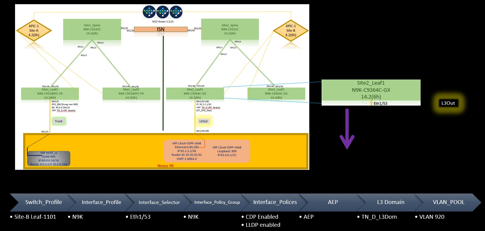
Optional Step
Once you have fabric policies in place for respective connections, you can ensure all leaf/spines are discovered and reachable from the respective APIC cluster. Next, you can validate both sites (APIC clusters) are reachable from MSO and the multi-site setup is operational (and IPN connectivity).
Configure RTEP/ETEP
Routable Tunnel Endpoint Pool (RTEP) or External Tunnel Endpoint Pool (ETEP) is the required configuration for intersite L3out. The older version of MSO displays "Routable TEP Pools" while the newer version of MSO displays "External TEP Pools", but both are synonymous. These TEP pools are used for Border Gateway Protocol (BGP) Ethernet VPN (EVPN) via VRF "Overlay-1".
External routes from L3out are advertised via BGP EVPN toward another site. This RTEP/ETEP is also used for remote leaf configuration, so if you have an ETEP/RTEP configuration that already exists in APIC then it must be imported in MSO.
Here are the steps to configure ETEP from the MSO GUI. Since the version is 3.X MSO, it displays ETEP. ETEP pools must be unique at each site and must not overlap with any internal EPG/BD subnet of each site.
Site-A
Step 1. In the MSO GUI page (open the multi-site controller in a web page), choose Infrastructure > Infra Configuration. Click Configure Infra.

Step 2. Inside Configure Infra, choose Site-A, Inside Site-A, choose pod-1. Then, inside pod-1, configure External TEP Pools with the external TEP IP address for Site-A. (In this example it is 192.168.200.0/24). If you have Multi-POD in Site-A, repeat this step for other pods.

Step 3. In order to verify the configuration of the ETEP pools in the APIC GUI, choose Fabric > Inventory > Pod Fabric Setup Policy > Pod-ID (double click to open [Fabric Setup Policy a POD-Pod-x]) > External TEP.

You can also verify the configuration with these commands:
moquery -c fabricExtRoutablePodSubnet
moquery -c fabricExtRoutablePodSubnet -f 'fabric.ExtRoutablePodSubnet.pool=="192.168.200.0/24"'
APIC1# moquery -c fabricExtRoutablePodSubnet
Total Objects shown: 1
# fabric.ExtRoutablePodSubnet
pool                 : 192.168.200.0/24
annotation           : orchestrator:msc
childAction          :
descr                :
dn                   : uni/controller/setuppol/setupp-1/extrtpodsubnet-[192.168.200.0/24]
extMngdBy            :
lcOwn                : local
modTs                : 2021-07-19T14:45:22.387+00:00
name                 :
nameAlias            :
reserveAddressCount  : 0
rn                   : extrtpodsubnet-[192.168.200.0/24]
state                : active
status               :
uid                  : 0
Site-B
Step 1. Configure the External TEP Pool for Site-B (The same steps as for Site-A.) In the MSO GUI page (open the multi-site controller in a web page), choose Infrastructure > Infra Configuration. Click Configure Infra. Inside Configure Infra, choose Site-B. Inside Site-B, choose pod-1. Then, inside pod-1, configure External TEP Pools with the external TEP IP address for Site-B. (In this example it is 192.168.100.0/24). If you have Multi-POD in Site-B, repeat this step for other pods.

Step 2. In order to verify the configuration of the ETEP pools in the APIC GUI, choose Fabric > Inventory > Pod Fabric Setup Policy > Pod-ID (double click to open [Fabric Setup Policy a POD-Pod-x]) > External TEP.
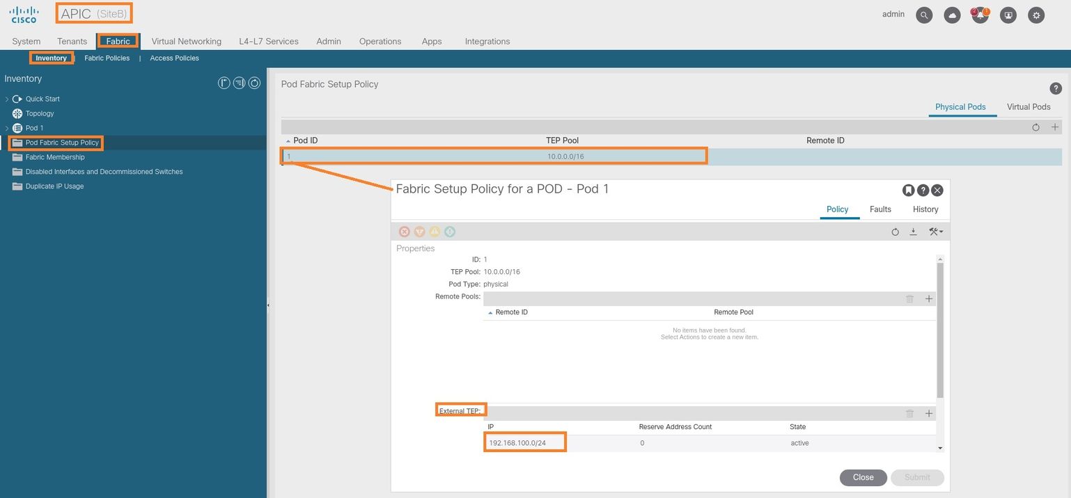
For the Site-B APIC, enter this command in order to verify the ETEP address pool.
apic1# moquery -c fabricExtRoutablePodSubnet -f 'fabric.ExtRoutablePodSubnet.pool=="192.168.100.0/24"'
Total Objects shown: 1
# fabric.ExtRoutablePodSubnet
pool                 : 192.168.100.0/24
annotation           : orchestrator:msc  <<< This means, configuration pushed from MSO.
childAction          :
descr                :
dn                   : uni/controller/setuppol/setupp-1/extrtpodsubnet-[192.168.100.0/24]
extMngdBy            :
lcOwn                : local
modTs                : 2021-07-19T14:34:18.838+00:00
name                 :
nameAlias            :
reserveAddressCount  : 0
rn                   : extrtpodsubnet-[192.168.100.0/24]
state                : active
status               :
uid                  : 0
Configure the Stretch Tenant
Step 1. In the MSO GUI, choose Application Management > Tenants. Click Add Tenant. In this example, the Tenant name is "TN_D".

Step 2. In the Display Name field, enter the tenant's name. In the Associated Sites section, check the Site A and Site B check boxes.
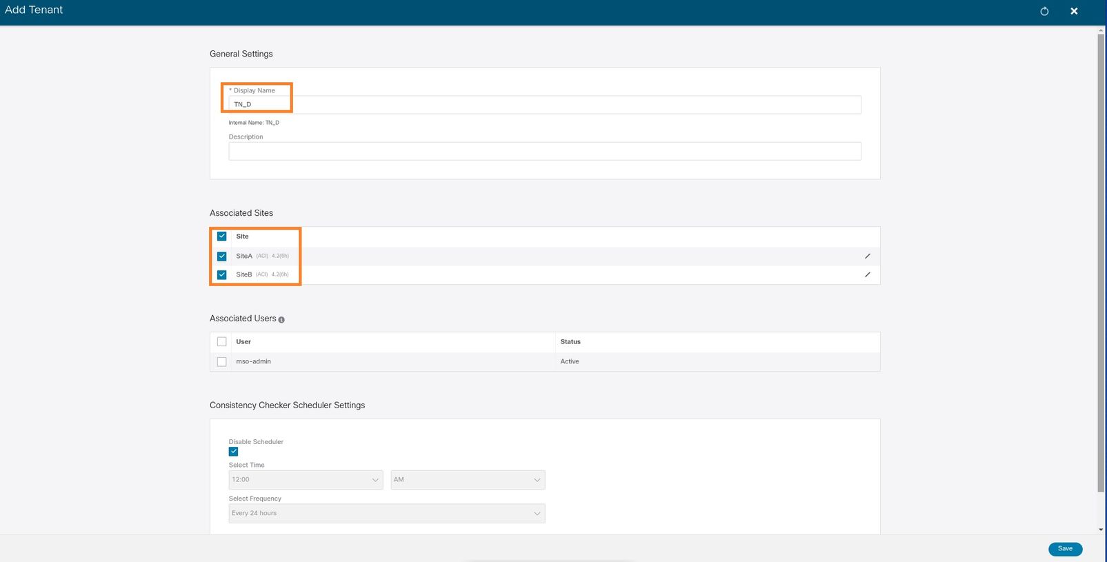
Step 3. Verify that the new tenant "Tn_D" is created.

Logical View
When we create a tenant from MSO, it basically creates a tenant at Site-A and Site-B. It is a stretch tenant. A logical view of this tenant is shown in this example. This logical view helps to understand that tenant TN_D is stretched tenant between Site-A and Site-B.
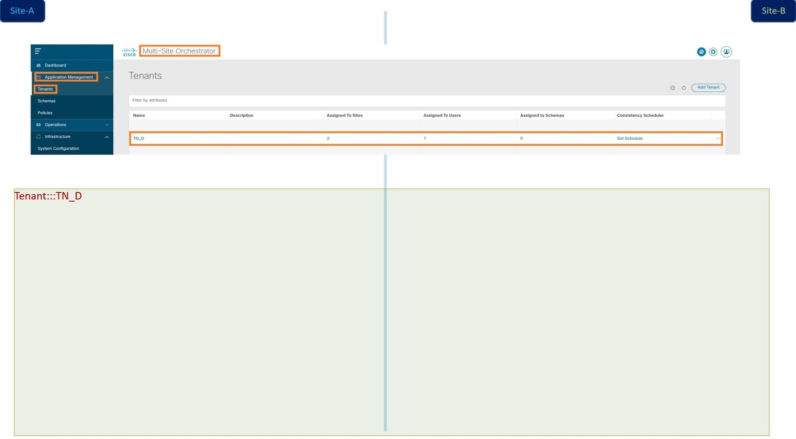
You can verify the logical view in the APIC of each site. You can see that Site-A and Site-B both show "TN_D" tenant created.

The same stretched tenant "TN_D" is also created in Site-B.

This command shows the tenant pushed from MSO and you can use it for verification purposes. You can run this command in the APIC of both sites.
APIC1# moquery -c fvTenant -f 'fv.Tenant.name=="TN_D"'
Total Objects shown: 1
# fv.Tenant
name         : TN_D
annotation   : orchestrator:msc
childAction  :
descr        :
dn           : uni/tn-TN_D
extMngdBy    : msc
lcOwn        : local
modTs        : 2021-09-17T21:42:52.218+00:00
monPolDn     : uni/tn-common/monepg-default
nameAlias    :
ownerKey     :
ownerTag     :
rn           : tn-TN_D
status       :
uid          : 0
apic1# moquery -c fvTenant -f 'fv.Tenant.name=="TN_D"'
Total Objects shown: 1
# fv.Tenant
name         : TN_D
annotation   : orchestrator:msc
childAction  :
descr        :
dn           : uni/tn-TN_D
extMngdBy    : msc
lcOwn        : local
modTs        : 2021-09-17T21:43:04.195+00:00
monPolDn     : uni/tn-common/monepg-default
nameAlias    :
ownerKey     :
ownerTag     :
rn           : tn-TN_D
status       :
uid          : 0
Configure the Schema
Next, create a schema that has a total of three templates:
- Template for Site-A: The template for Site-A only associates with Site-A, hence whatever logical object configuration in that template can only push to the APIC of Site-A.
- Template for Site-B: The template for Site-B only associates with Site-B, hence whatever logical object configuration in that template can only push to the APIC of Site-B.
- Stretched Template: The stretched template associates with both sites and any logical configuration in the stretched template can push to both sites of APICs.
Create the Schema
Schema is locally significant in MSO, it does not create any object in APIC. Schema configuration is the logical separation of each configuration. You can have multiple schema for the same tenants, and you can also have multiple templates inside each schema.
For example, you can have a schema for the database server for tenant X and the application server uses a different schema for the same tenant-X. This can help to separate each specific application-related configuration and is easy when you need to debug an issue. It is also easy to find information.
Create a schema with the name of the tenant (for example, TN_D_Schema). However, it is not necessary to have the name of schema start with the tenant name, you can create a schema with any name.
Step 1. Choose Application Management > Schemas. Click Add Schema.

Step 2. In the Name field, enter the name of the schema. In this example it is "TN_D_Schema", however you can keep any name which is appropriate for your environment. Click Add.

Step 3. Verify that schema "TN_D_Schema" was created.
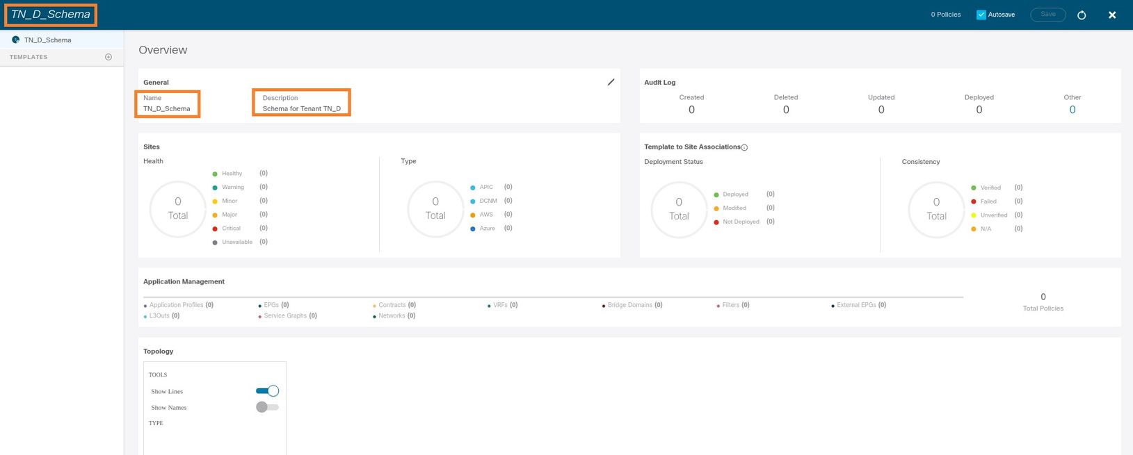
Create the Site-A Template
Step 1. Add a template inside the schema.
- In order to create a template, click Templates under the schema which you have created. The Select a Template type dialog box is displayed.
- Choose ACI Multi-cloud.
- Click Add.

Step 2. Enter a name for the template. This template is specific to Site-A, hence the template name "Site-A Template". Once the template is created, you can attach a specific tenant to the template. In this example, the tenant "TN_D" is attached.

Configure the Template
Application Profile Configuration
Step 1. From the schema that you created, choose Site-A Template. Click Add Application Profile.

Step 2. In the Display Name field, enter the application profile name App_Profile.
Step 3. The next step is to create EPG. In order to add EPG under the application profile, click Add EPG under the Site-A template. You can see a new EPG is created inside the EPG configuration.

Step 4. In order to attach EPG with BD and VRF, you have to add BD and VRF under EPG. Choose Site-A Template. In the Display Name field, enter the name of the EPG and attach a new BD (you can create a new BD or attach an existing BD).

Note that you have to attach VRF to a BD, but VRF is stretched in this case. You can create the stretched template with stretched VRF and then attach that VRF to BD under site specific template (in our case it is Site-A Template).
Create the Stretch Template
Step 1. In order to create the stretch template, under the TN_D_Schema click Templates. The Select a Template type dialog box is displayed. Choose ACI Multi-cloud. Click Add. Enter the name Stretched Template for the template. (You can enter any name for the stretched template.)

Step 2. Choose Stretched Template and create a VRF with the name VRF_Stretch. (You can enter any name for VRF.)

BD was created with the EPG creation under Site-A Template, but there were no VRF attached, hence you have to attach VRF which is now reated in the Stretched Template.
Step 3. Choose Site-A Template > BD_990. In the Virtual Routing & Forwarding drop-down list, choose VRF_Stretch. (The one you created in Step 2 of this section.)

Attach the Template
The next step is to attach the Site-A Template with Site-A only, and the stretched template needs to be attached to both sites. Click Deploy to site inside the schema in order to deploy templates to the respective sites.
Step 1. Click the + sign under TN_D_Schema > SITES to add sites to template. In the Assign to Template drop-down list, choose the respective template for the appropriate sites.
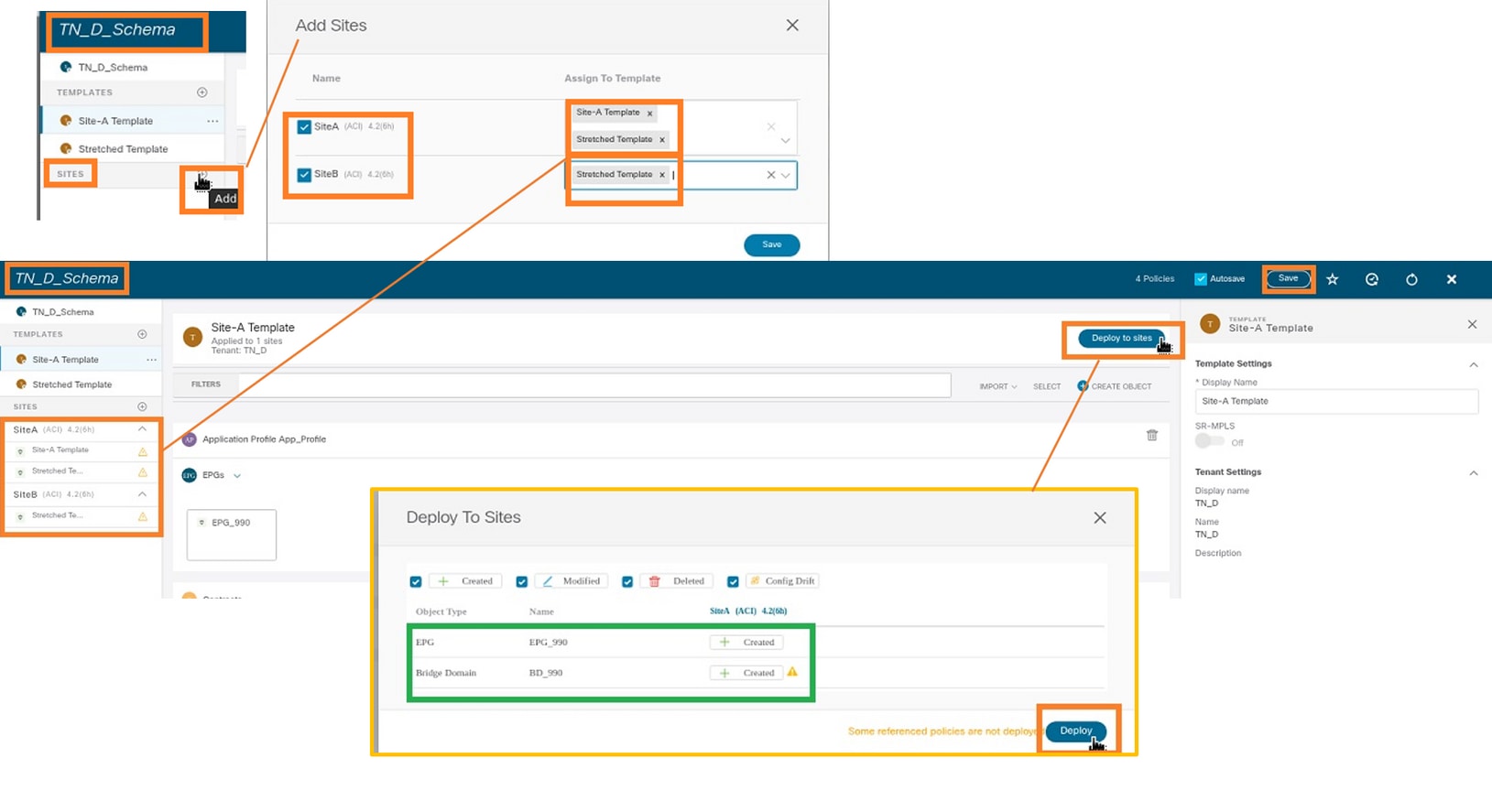
Step 2. You can see Site-A has EPG and BD now create but Site-B does not have same EPG/BD created because those configuration only applies to Site-A from MSO. However, you can see VRF is created in the Stretched Template hence it is created in both sites.

Step 3. Verify the configuration with these commands.
APIC1# moquery -c fvAEPg -f 'fv.AEPg.name=="EPG_990"'
Total Objects shown: 1
# fv.AEPg
name                 : EPG_990
annotation           : orchestrator:msc
childAction          :
configIssues         :
configSt             : applied
descr                :
dn                   : uni/tn-TN_D/ap-App_Profile/epg-EPG_990
exceptionTag         :
extMngdBy            :
floodOnEncap         : disabled
fwdCtrl              :
hasMcastSource       : no
isAttrBasedEPg       : no
isSharedSrvMsiteEPg  : no
lcOwn                : local
matchT               : AtleastOne
modTs                : 2021-09-18T08:26:49.906+00:00
monPolDn             : uni/tn-common/monepg-default
nameAlias            :
pcEnfPref            : unenforced
pcTag                : 32770
prefGrMemb           : exclude
prio                 : unspecified
rn                   : epg-EPG_990
scope                : 2850817
shutdown             : no
status               :
triggerSt            : triggerable
txId                 : 1152921504609182523
uid                  : 0
APIC1# moquery -c fvBD -f 'fv.BD.name=="BD_990"'
Total Objects shown: 1
# fv.BD
name                     : BD_990
OptimizeWanBandwidth     : yes
annotation               : orchestrator:msc
arpFlood                 : yes
bcastP                   : 225.0.56.224
childAction              :
configIssues             :
descr                    :
dn                       : uni/tn-TN_D/BD-BD_990
epClear                  : no
epMoveDetectMode         :
extMngdBy                :
hostBasedRouting         : no
intersiteBumTrafficAllow : yes
intersiteL2Stretch       : yes
ipLearning               : yes
ipv6McastAllow           : no
lcOwn                    : local
limitIpLearnToSubnets    : yes
llAddr                   : ::
mac                      : 00:22:BD:F8:19:FF
mcastAllow               : no
modTs                    : 2021-09-18T08:26:49.906+00:00
monPolDn                 : uni/tn-common/monepg-default
mtu                      : inherit
multiDstPktAct           : bd-flood
nameAlias                :
ownerKey                 :
ownerTag                 :
pcTag                    : 16387
rn                       : BD-BD_990
scope                    : 2850817
seg                      : 16580488
status                   :
type                     : regular
uid                      : 0
unicastRoute             : yes
unkMacUcastAct           : proxy
unkMcastAct              : flood
v6unkMcastAct            : flood
vmac                     : not-applicable
               : 0
APIC1# moquery -c fvCtx -f 'fv.Ctx.name=="VRF_Stretch"'
Total Objects shown: 1
# fv.Ctx
name                 : VRF_Stretch
annotation           : orchestrator:msc
bdEnforcedEnable     : no
childAction          :
descr                :
dn                   : uni/tn-TN_D/ctx-VRF_Stretch
extMngdBy            :
ipDataPlaneLearning  : enabled
knwMcastAct          : permit
lcOwn                : local
modTs                : 2021-09-18T08:26:58.185+00:00
monPolDn             : uni/tn-common/monepg-default
nameAlias            :
ownerKey             :
ownerTag             :
pcEnfDir             : ingress
pcEnfDirUpdated      : yes
pcEnfPref            : enforced
pcTag                : 16386
rn                   : ctx-VRF_Stretch
scope                : 2850817
seg                  : 2850817
status               :
uid                  : 0
Configure Static Port Bind
You can now configure static port bind under EPG "EPG_990" and also configure the N9K with VRF HOST_A (basically it simulates HOST_A). The ACI side static port bind configuration will be completed first.
Step 1. Add the physical domain under EPG_990.
- From the schema that you created, choose Site-A Template > EPG_990.
- In the Template Properties box, click Add Domain.
- In the Add Domain dialog box, choose these options from the drop-down lists:
- Domain Association Type - Physical
- Domain Profile - TN_D_PhysDom
- Deployment Immediacy - Immediate
- Resolution Immediacy - Immediate
- Click Save.

Step 2. Add the static port (Site1_Leaf1 eth1/5).
- From the schema that you created, choose Site-A Template > EPG_990.
- In the Template Properties box, click Add Static Port.
- In the Add Static EPG on PC, VPC or Interface dialog box, choose Node-101 eth1/5 and assign VLAN 990.

Step 3. Ensure the static ports and physical domain are added under EPG_990.
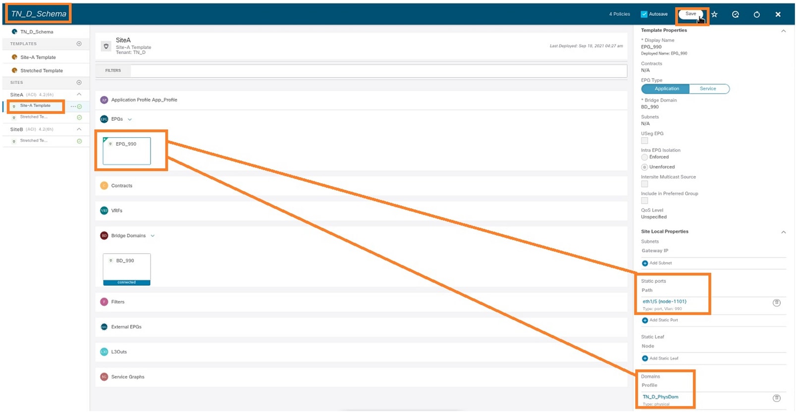
Verify the static path bind with this command:
APIC1# moquery -c fvStPathAtt -f 'fv.StPathAtt.pathName=="eth1/5"' | grep EPG_990 -A 10 -B 5
# fv.StPathAtt
pathName     : eth1/5
childAction  :
descr        :
dn           : uni/epp/fv-[uni/tn-TN_D/ap-App_Profile/epg-EPG_990]/node-1101/stpathatt-[eth1/5]
lcOwn        : local
modTs        : 2021-09-19T06:16:46.226+00:00
monPolDn     : uni/tn-common/monepg-default
name         :
nameAlias    :
ownerKey     :
ownerTag     :
rn           : stpathatt-[eth1/5]
status       :
Configure BD
Step 1. Add the subnet/IP under BD (HOST_A uses BD IP as the gateway).
- From the schema that you created, choose Site-A Template > BD_990.
- Click Add Subnet.
- In the Add New Subnet dialog box, enter the Gateway IP address and click the Advertised Externally radio button.
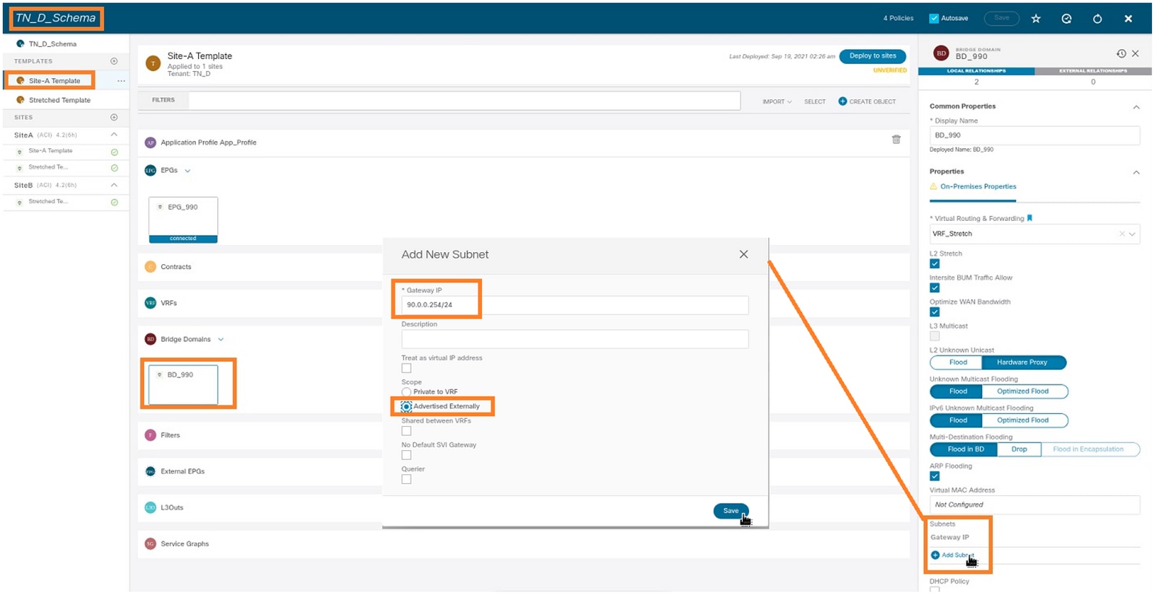
Step 2. Verify that the subnet is added in APIC1 Site-A with this command.
APIC1# moquery -c fvSubnet -f 'fv.Subnet.ip=="90.0.0.254/24"'
Total Objects shown: 1

# fv.Subnet
ip           : 90.0.0.254/24
annotation   : orchestrator:msc
childAction  :
ctrl         : nd
descr        :
dn           : uni/tn-TN_D/BD-BD_990/subnet-[90.0.0.254/24]
extMngdBy    :
lcOwn        : local
modTs        : 2021-09-19T06:33:19.943+00:00
monPolDn     : uni/tn-common/monepg-default
name         :
nameAlias    :
preferred    : no
rn           : subnet-[90.0.0.254/24]
scope        : public
status       :
uid          : 0
virtual      : no
Step 3. Deploy the Site-A template.
- From the schema that you created, choose Site-A Template.
- Click Deploy to sites.
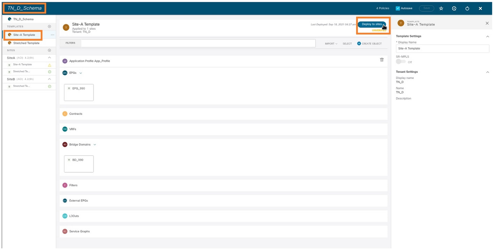
Configure Host-A (N9K)
Configure the N9K device with VRF HOST_A. Once the N9K configuration completes, you can see ACI Leaf BD anycast address (gateway of HOST_A) is reachable now via ICMP(ping).

In the ACI operational tab, you can see 90.0.0.10 (HOST_A IP address) is learned.
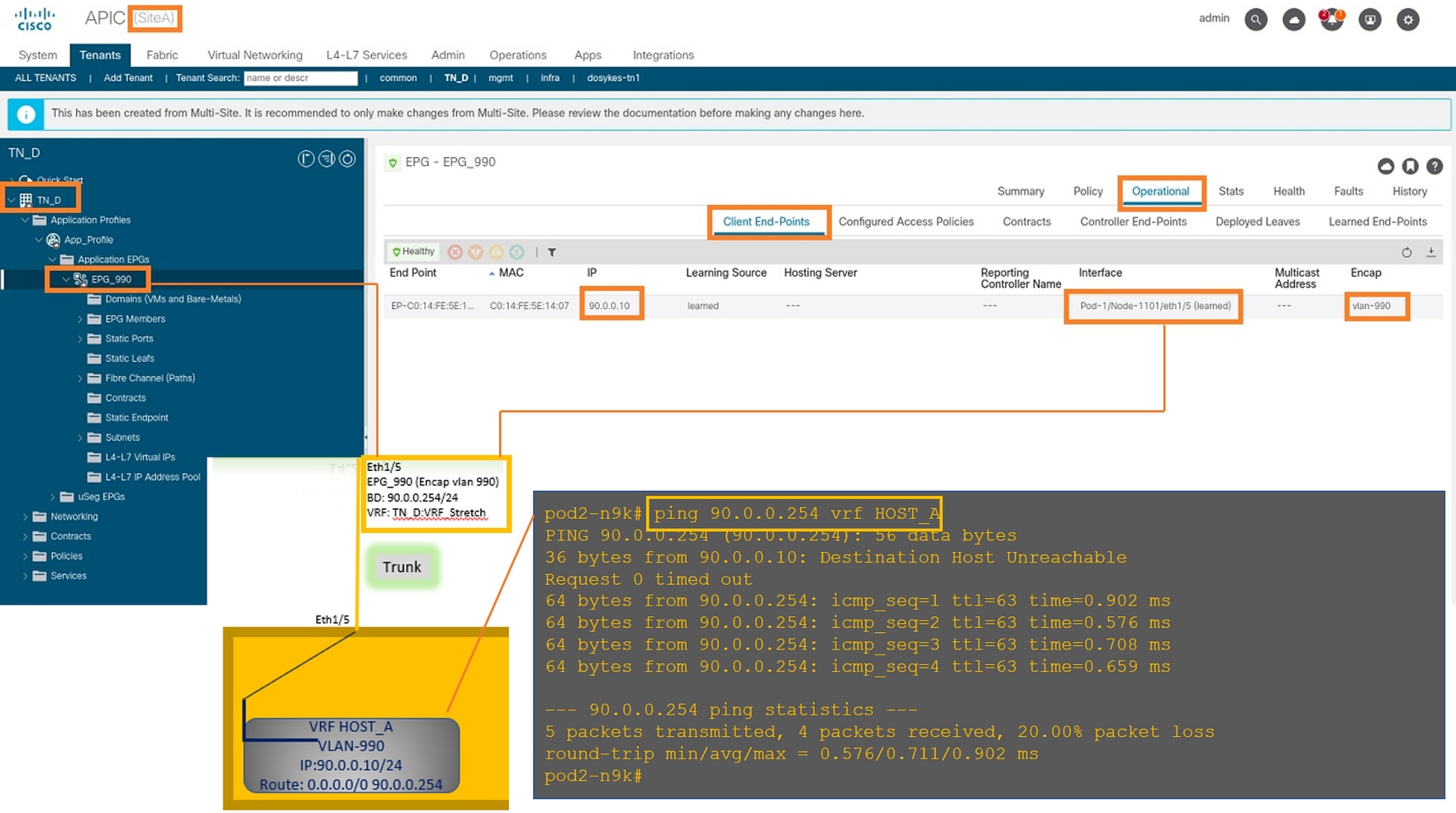
Create the Site-B Template
Step 1. From the schema that you created, choose TEMPLATES. Click the + sign and create a template with the name Site-B Template.

Configure Site-B L3out
Create L3out and attach VRF_Stretch. You have to create an L3out object from MSO and the rest of the L3out configuration needs to be done from APIC (as L3out parameters are not available in MSO). Also, create an external EPG from MSO (in the Site-B template only, as external EPG is not stretched).
Step 1. From the schema that you created, choose Site-B Template. In the Display Name field, enter L3out_OSPF_siteB. In the Virtual Routing & Forwarding drop-down list, choose VRF_Stretch.
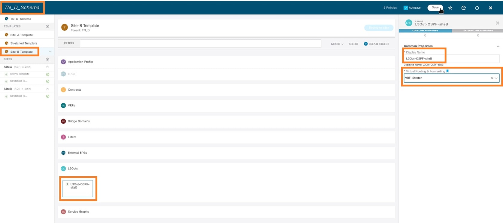
Create the External EPG
Step 1. From the schema that you created, choose Site-B Template. Click Add External EPG.

Step 2. Attach L3out with External EPG.
- From the schema that you created, choose Site-B Template.
- In the Display Name field, enter EXT_EPG_Site2.
- In the Classification Subnets field, enter 0.0.0.0/0 for the external subnet for external EPG.

The rest of the L3out configuration is completed from APIC (Site-B).
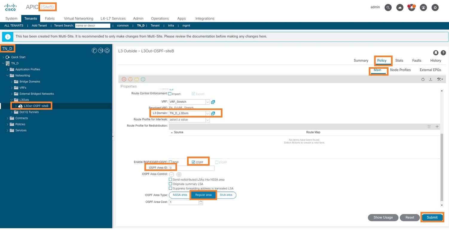
Step 3. Add the L3 domain, enable the OSPF protocol, and configure OSPF with regular area 0.
- From APIC-1 at Site-B, choose TN_D > Networking > L3out-OSPF-siteB > Policy > Main.
- In the L3 Domain drop-down list, choose TN_D_L3Dom.
- Check the OSPF check box for Enable BGP/EIGRP/OSPF.
- In the OSPF Area ID field, enter 0.
- In the OSPF Area Type, choose Regular area.
- Click Submit.
Step 4. Create the node profile.
- From APIC-1 at Site-B, choose TN_D > Networking > L3Outs > L3Out-OSPF-siteB > Logical Node Profiles.
- Click Create Node Profile.

Step 5. Choose switch Site2_Leaf1 as a node at site-B.
- From APIC-1 at Site-B, choose TN_D > Networking > L3Outs > L3Out-OSPF-siteB > Logical Node Profiles > Create Node Profile.
- In the Name field, enter Site2_Leaf1.
- Click the + sign to add a node.
- Add the pod-2 node-101 with the router ID IP address.

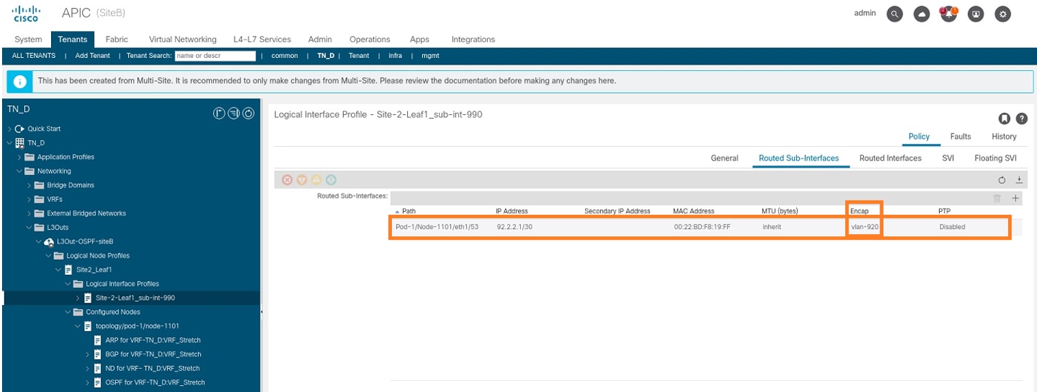
Step 6. Add the Interface profile (External VLAN is 920 (SVI creation)).
- From APIC-1 at Site-B, choose TN_D > Networking > L3Outs > L3out-OSPF-SiteB > Logical Interface Profiles.
- Right-click and add the interface profile.
- Choose Routed Sub-Interfaces.
- Configure the IP Address, MTU, and VLAN-920.
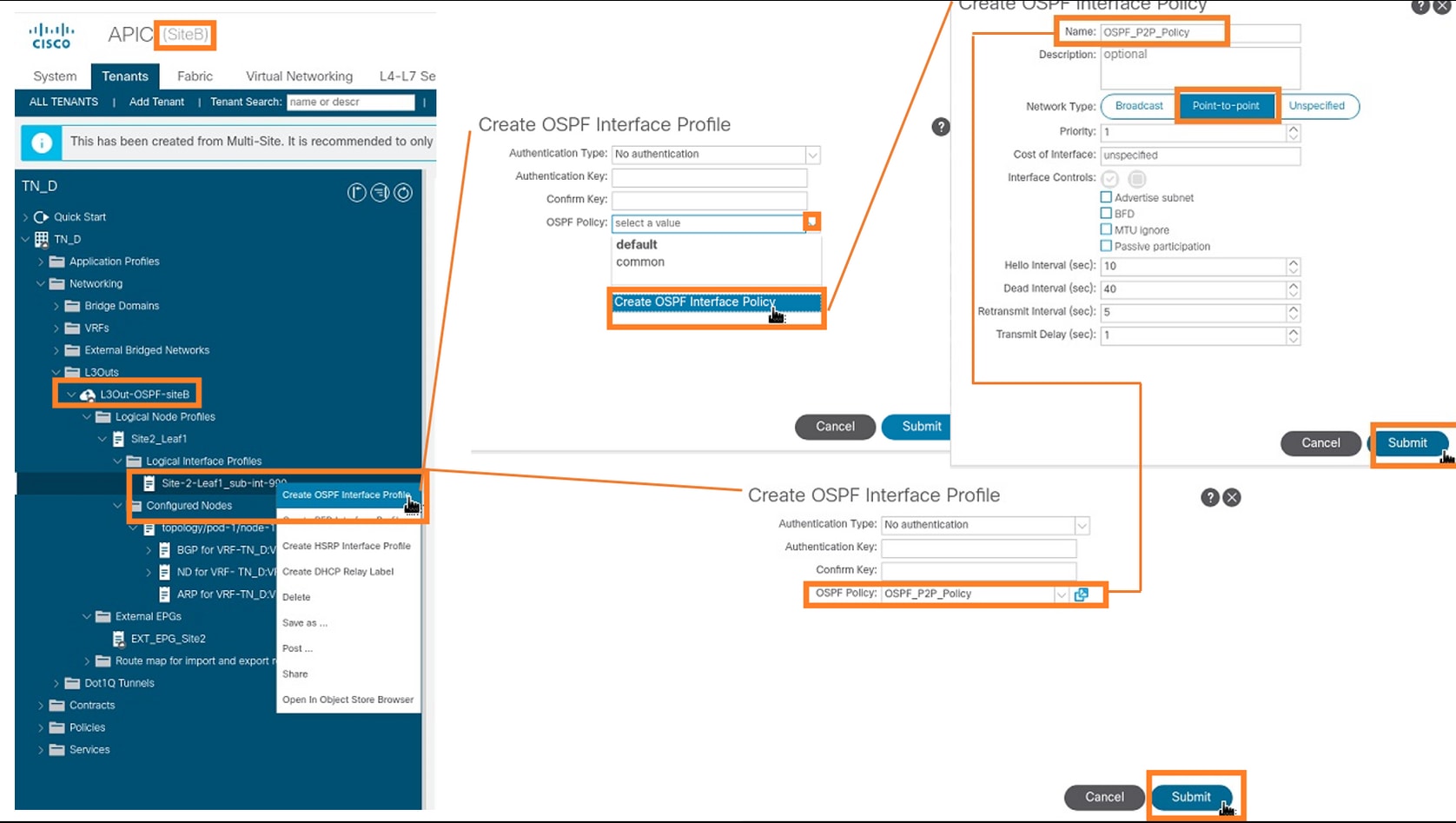
Step 7. Create the OSPF policy (Point to Point Network).
- From APIC-1 at Site-B, choose TN_D > Networking > L3Outs > L3Out-OSPF-siteB > Logical Interface Profiles.
- Right-click and choose Create OSPF Interface Profile.
- Choose the options as shown in the screenshot and click Submit.
Step 8. Verify the OSPF interface profile policy attached under TN_D > Networking > L3Outs > L3Out-OSPF-siteB > Logical Interface Profiles > (interface profile) > OSPF Interface Profile.

Step 9. Verify External EPG "EXT_EPG_Site2" is created by MSO. From APIC-1 at Site-B, choose TN_D > L3Outs > L3Out-OSPF-siteB > External EPGs > EXT_EPG_Site2.

Configure the External N9K (Site-B)
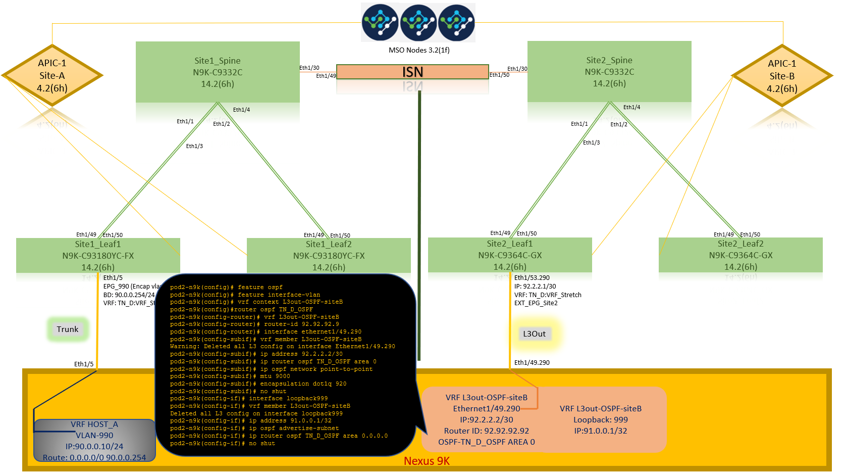
After the N9K configuration (VRF L3out-OSPF-siteB), we can see OSPF neighborship is established between the N9K and the ACI Leaf (at Site-B).
Verify OSPF neighborship is established and UP (Full State).
From APIC-1 at Site-B, choose TN_D > Networking > L3Outs > L3Out-OSPF-siteB > Logical Node Profiles > Logical Interface Profiles > Configured Nodes > topology/pod01/node-1101 > OSPF for VRF-TN_DVRF_Switch > Neighbor ID state > Full.
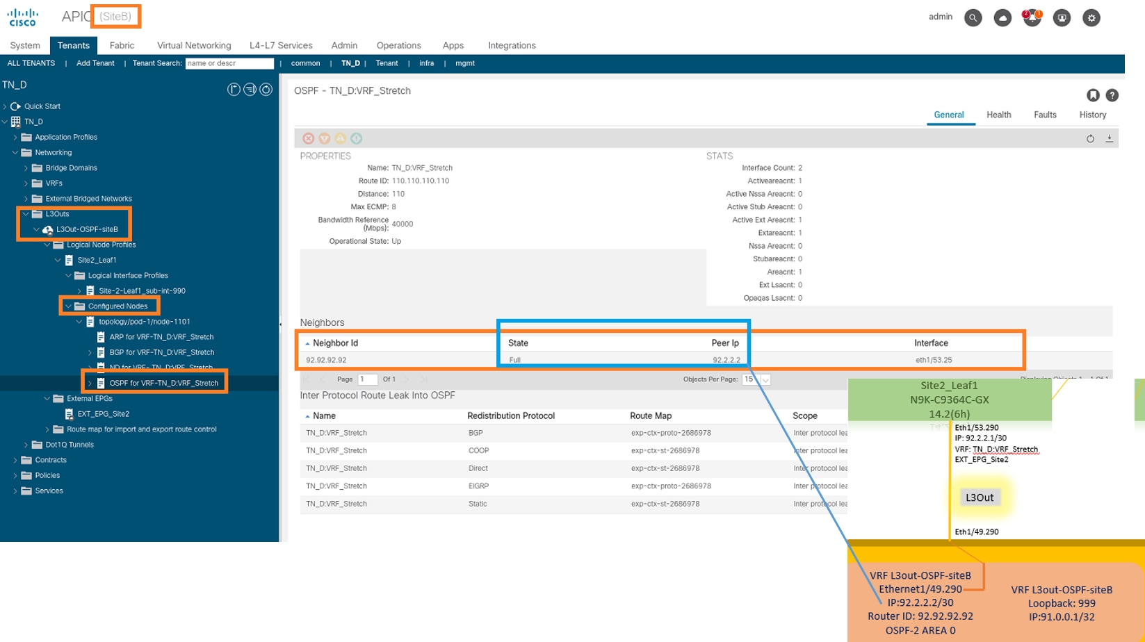
You can also check OSPF neighborship in N9K. Also, you are able to ping ACI Leaf IP (Site-B).

At this point, Host_A configuration at site-A and L3out configuration at site-B is complete.

Attach Site-B L3out to Site-A EPG(BD)
Next, you can attach Site-B L3out to Site-A BD-990 from MSO. Note that the left side column has two sections: 1) Template and 2) Sites.
Step 1. In the second section Sites, you can see the template attached with each site. When you attach L3out to "Site-A Template", you are basically attached from the already attached template inside the Sites section.
However, when you deploy the template, deploy from section Templates > Site-A Template and choose save/deploy to sites.


Step 2. Deploy from main template "Site-A Template" in first section "Templates".

Configure the Contract
You require a contract between External EPG at site-B and Internal EPG_990 at site-A. So, you can first create a contract from MSO and attach it to both EPGs.
Cisco Application Centric Infrastructure - Cisco ACI Contract Guide can help to understand the contract. Generally, internal EPG is configured as a provider and external EPG is configured as a consumer.

Create the Contract
Step 1. From TN_D_Schema, choose Stretched Template > Contracts. Click Add Contract.

Step 2. Add a filter to allow all traffic.
- From TN_D_Schema, choose Stretched Template > Contracts.
- Add a contract with:
- Display Name: Intersite-L3out-Contract
- Scope: VRF

Step 3.
- From TN_D_Schema, choose Stretched Template > Filters.
- In the Display Name field, enter Allow-all-traffic.
- Click Add Entry. The Add Entry dialog box displays.
- In the Name field, enter Any_Traffic.
- In the Ether Type drop-down list, choose unspecified to allow all traffic.
- Click Save.

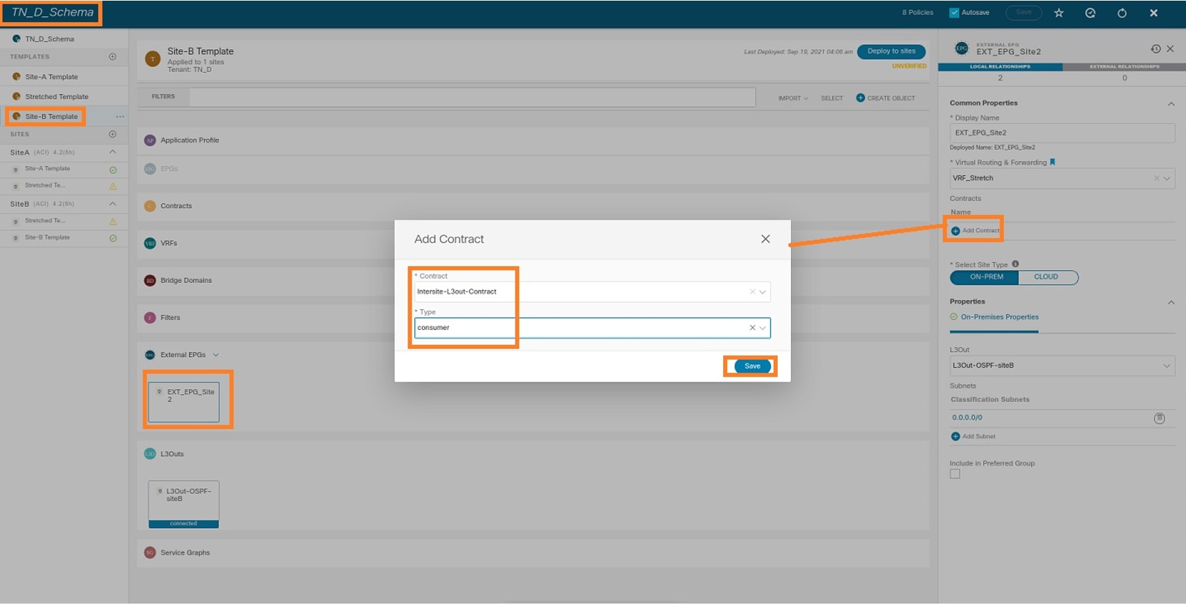
Step 4. Add contract to External EPG as "Consumer" (In Site-B Template) (Deploy to the site).
- From TN_D_Schema, choose Site-B Template > EXT_EPG_Site2.
- Click Add Contract. The Add Contract dialog box displays.
- In the Contract field, enter Intersite-L3out-Contract.
- In the Type drop-down list, choose consumer.
Step 5. Add contract to Internal EPG "EPG_990" as "Provider" (In Site-A Template) (Deploy to site).
- From TN_D_Schema, choose Site-A Template > EPG_990.
- Click Add Contract. The Add Contract dialog box displays.
- In the Contract field, enter Intersite-L3out-Contract.
- In the Type drop-down list, choose provider.

As soon as the contract gets added, you can see "Shadow L3out / External EPG" created at Site-A.

You can also see that "Shadow EPG_990 and BD_990" were also created at Site-B.

Step 6. Enter these commands in order to verify Site-B APIC.
apic1# moquery -c fvAEPg -f 'fv.AEPg.name=="EPG_990"'
Total Objects shown: 1
# fv.AEPg
name                 : EPG_990
annotation           : orchestrator:msc
childAction          :
configIssues         :
configSt             : applied
descr                :
dn                   : uni/tn-TN_D/ap-App_Profile/epg-EPG_990
exceptionTag         :
extMngdBy            :
floodOnEncap         : disabled
fwdCtrl              :
hasMcastSource       : no
isAttrBasedEPg       : no
isSharedSrvMsiteEPg  : no
lcOwn                : local
matchT               : AtleastOne
modTs                : 2021-09-19T18:47:53.374+00:00
monPolDn             : uni/tn-common/monepg-default
nameAlias            :
pcEnfPref            : unenforced
pcTag                : 49153          <<< Note that pcTag is different for shadow EPG.
prefGrMemb           : exclude
prio                 : unspecified
rn                   : epg-EPG_990
scope                : 2686978
shutdown             : no
status               :
triggerSt            : triggerable
txId                 : 1152921504609244629
uid                  : 0
apic1# moquery -c fvBD -f 'fv.BD.name==\"BD_990\"'
Total Objects shown: 1
# fv.BD
name                     : BD_990
OptimizeWanBandwidth     : yes
annotation               : orchestrator:msc
arpFlood                 : yes
bcastP                   : 225.0.181.192
childAction              :
configIssues             :
descr                    :
dn                       : uni/tn-TN_D/BD-BD_990
epClear                  : no
epMoveDetectMode         :
extMngdBy                :
hostBasedRouting         : no
intersiteBumTrafficAllow : yes
intersiteL2Stretch       : yes
ipLearning               : yes
ipv6McastAllow           : no
lcOwn                    : local
limitIpLearnToSubnets    : yes
llAddr                   : ::
mac                      : 00:22:BD:F8:19:FF
mcastAllow               : no
modTs                    : 2021-09-19T18:47:53.374+00:00
monPolDn                 : uni/tn-common/monepg-default
mtu                      : inherit
multiDstPktAct           : bd-flood
nameAlias                :
ownerKey                 :
ownerTag                 :
pcTag                    : 32771
rn                       : BD-BD_990
scope                    : 2686978
seg                      : 15957972
status                   :
type                     : regular
uid                      : 0
unicastRoute             : yes
unkMacUcastAct           : proxy
unkMcastAct              : flood
v6unkMcastAct            : flood
vmac                     : not-applicable
Step 7. Review and verify the external device N9K configuration.

Verify
Use this section to confirm that your configuration works properly.
Endpoint Learn
Verify the Site-A endpoint was learned as an endpoint in Site1_Leaf1.
Site1_Leaf1# show endpoint interface ethernet 1/5
Legend:
 s - arp              H - vtep             V - vpc-attached     p - peer-aged
 R - peer-attached-rl B - bounce           S - static           M - span
 D - bounce-to-proxy  O - peer-attached    a - local-aged       m - svc-mgr
 L - local            E - shared-service
+-----------------------------------+---------------+-----------------+--------------+-------------+
      VLAN/                           Encap           MAC Address       MAC Info/       Interface
      Domain                          VLAN            IP Address        IP Info
+-----------------------------------+---------------+-----------------+--------------+-------------+
18                                         vlan-990    c014.fe5e.1407 L                      eth1/5
TN_D:VRF_Stretch                           vlan-990         90.0.0.10 L                      eth1/5
ETEP/RTEP Verification
Site_A Leafs.
Site1_Leaf1# show ip interface brief vrf overlay-1
IP Interface Status for VRF "overlay-1"(4)
Interface            Address              Interface Status
eth1/49              unassigned           protocol-up/link-up/admin-up
eth1/49.7            unnumbered           protocol-up/link-up/admin-up
                     (lo0)
eth1/50              unassigned           protocol-up/link-up/admin-up
eth1/50.8            unnumbered           protocol-up/link-up/admin-up
                     (lo0)
eth1/51              unassigned           protocol-down/link-down/admin-up
eth1/52              unassigned           protocol-down/link-down/admin-up
eth1/53              unassigned           protocol-down/link-down/admin-up
eth1/54              unassigned           protocol-down/link-down/admin-up
vlan9                10.0.0.30/27         protocol-up/link-up/admin-up
lo0                  10.0.80.64/32        protocol-up/link-up/admin-up
lo1                  10.0.8.67/32         protocol-up/link-up/admin-up
lo8                  192.168.200.225/32   protocol-up/link-up/admin-up  <<<<< IP from ETEP  site-A
lo1023               10.0.0.32/32         protocol-up/link-up/admin-up
Site2_Leaf1# show ip interface brief vrf overlay-1
IP Interface Status for VRF "overlay-1"(4)
Interface            Address              Interface Status
eth1/49              unassigned           protocol-up/link-up/admin-up
eth1/49.16           unnumbered           protocol-up/link-up/admin-up
                     (lo0)
eth1/50              unassigned           protocol-up/link-up/admin-up
eth1/50.17           unnumbered           protocol-up/link-up/admin-up
                     (lo0)
eth1/51              unassigned           protocol-down/link-down/admin-up
eth1/52              unassigned           protocol-down/link-down/admin-up
eth1/54              unassigned           protocol-down/link-down/admin-up
eth1/55              unassigned           protocol-down/link-down/admin-up
eth1/56              unassigned           protocol-down/link-down/admin-up
eth1/57              unassigned           protocol-down/link-down/admin-up
eth1/58              unassigned           protocol-down/link-down/admin-up
eth1/59              unassigned           protocol-down/link-down/admin-up
eth1/60              unassigned           protocol-down/link-down/admin-up
eth1/61              unassigned           protocol-down/link-down/admin-up
eth1/62              unassigned           protocol-down/link-down/admin-up
eth1/63              unassigned           protocol-down/link-down/admin-up
eth1/64              unassigned           protocol-down/link-down/admin-up
vlan18               10.0.0.30/27         protocol-up/link-up/admin-up
lo0                  10.0.72.64/32        protocol-up/link-up/admin-up
lo1                  10.0.80.67/32        protocol-up/link-up/admin-up
lo6                  192.168.100.225/32   protocol-up/link-up/admin-up <<<<< IP from ETEP site-B
lo1023               10.0.0.32/32         protocol-up/link-up/admin-up
ICMP Reachability
Ping the external device WAN IP address from HOST_A.

Ping the external device loopback address.

Route Verification
Verify the external device WAN IP address OR the loopback subnet route is present in the routing table. When you check the next hop for external device subnet in "Site1_Leaf1", it is the External TEP IP of Leaf "Site2-Leaf1".
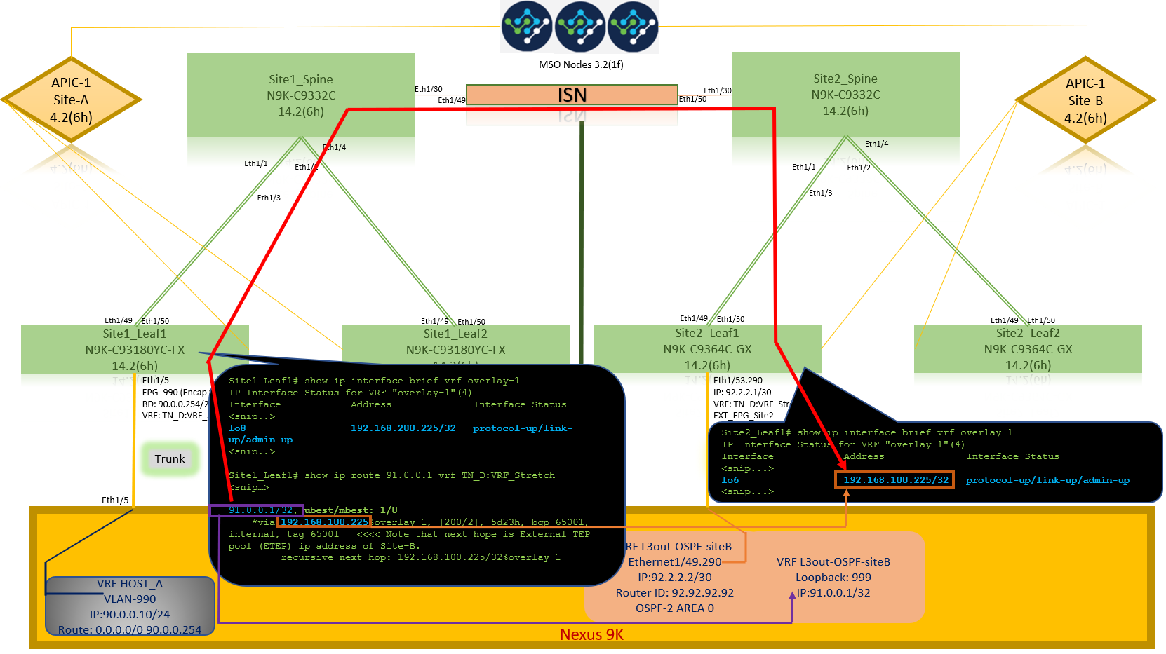
Site1_Leaf1# show ip route 92.2.2.2 vrf TN_D:VRF_Stretch
IP Route Table for VRF "TN_D:VRF_Stretch"
'*' denotes best ucast next-hop
'**' denotes best mcast next-hop
'[x/y]' denotes [preference/metric]
'%' in via output denotes VRF
92.2.2.0/30, ubest/mbest: 1/0
    *via 192.168.100.225%overlay-1, [200/0], 5d23h, bgp-65001, internal, tag 65001   <<<< Note that next hope is External TEP pool (ETEP) ip address of Site-B.
         recursive next hop: 192.168.100.225/32%overlay-1
Site1_Leaf1# show ip route 91.0.0.1 vrf TN_D:VRF_Stretch
IP Route Table for VRF "TN_D:VRF_Stretch"
'*' denotes best ucast next-hop
'**' denotes best mcast next-hop
'[x/y]' denotes [preference/metric]
'%' in via output denotes VRF
91.0.0.1/32, ubest/mbest: 1/0
    *via 192.168.100.225%overlay-1, [200/2], 5d23h, bgp-65001, internal, tag 65001   <<<< Note that next hope is External TEP pool (ETEP) ip address of Site-B.
         recursive next hop: 192.168.100.225/32%overlay-1
Troubleshoot
This section provides information you can use to troubleshoot your configuration.
Site2_Leaf1
BGP address-family route import/export between TN_D:VRF_stretch and Overlay-1.
Site2_Leaf1# show system internal epm vrf TN_D:VRF_Stretch
+--------------------------------+--------+----------+----------+------+--------
               VRF                  Type    VRF vnid  Context ID Status Endpoint
                                                                          Count
+--------------------------------+--------+----------+----------+------+--------
  TN_D:VRF_Stretch                  Tenant   2686978    46         Up     1

Site2_Leaf1# show vrf TN_D:VRF_Stretch detail
VRF-Name: TN_D:VRF_Stretch, VRF-ID: 46, State: Up
    VPNID: unknown
    RD: 1101:2686978
    Max Routes: 0  Mid-Threshold: 0
    Table-ID: 0x8000002e, AF: IPv6, Fwd-ID: 0x8000002e, State: Up
    Table-ID: 0x0000002e, AF: IPv4, Fwd-ID: 0x0000002e, State: Up


Site2_Leaf1# vsh
Site2_Leaf1# show bgp vpnv4 unicast 91.0.0.1 vrf TN_D:VRF_Stretch
BGP routing table information for VRF overlay-1, address family VPNv4 Unicast
Route Distinguisher: 1101:2686978    (VRF TN_D:VRF_Stretch)
BGP routing table entry for 91.0.0.1/32, version 12 dest ptr 0xae6da350
Paths: (1 available, best #1)
Flags: (0x80c0002 00000000) on xmit-list, is not in urib, exported
  vpn: version 346, (0x100002) on xmit-list
Multipath: eBGP iBGP

  Advertised path-id 1, VPN AF advertised path-id 1
  Path type: redist 0x408 0x1 ref 0 adv path ref 2, path is valid, is best path
  AS-Path: NONE, path locally originated
    0.0.0.0 (metric 0) from 0.0.0.0 (10.0.72.64)
      Origin incomplete, MED 2, localpref 100, weight 32768
      Extcommunity:
          RT:65001:2686978
          VNID:2686978
          COST:pre-bestpath:162:110
  VRF advertise information:
  Path-id 1 not advertised to any peer
  VPN AF advertise information:
  Path-id 1 advertised to peers:
    10.0.72.65                                      <<<Spine site-2 'Site2_Spine'

Site-B
apic1# acidiag fnvread
      ID   Pod ID                 Name    Serial Number         IP Address    Role        State   LastUpdMsgId
--------------------------------------------------------------------------------------------------------------
     101        1          Site2_Spine      FDO243207JH      10.0.72.65/32   spine         active   0
     102        1          Site2_Leaf2      FDO24260FCH      10.0.72.66/32    leaf         active   0
    1101        1          Site2_Leaf1      FDO24260ECW      10.0.72.64/32    leaf         active   0
Site2_Spine


Site2_Spine# vsh
Site2_Spine# show bgp vpnv4 unicast 91.0.0.1 vrf overlay-1
BGP routing table information for VRF overlay-1, address family VPNv4 Unicast                             <---------26bits--------->
Route Distinguisher: 1101:2686978                                               <<<<<2686978 <--Binary--> 00001010010000000000000010
BGP routing table entry for 91.0.0.1/32, version 717 dest ptr 0xae643d0c
Paths: (1 available, best #1)
Flags: (0x000002 00000000) on xmit-list, is not in urib, is not in HW
Multipath: eBGP iBGP
  Advertised path-id 1
  Path type: internal 0x40000018 0x800040 ref 0 adv path ref 1, path is valid, is best path
  AS-Path: NONE, path sourced internal to AS
    10.0.72.64 (metric 2) from 10.0.72.64 (10.0.72.64)  <<< Site2_leaf1 IP
      Origin incomplete, MED 2, localpref 100, weight 0
      Received label 0
      Received path-id 1
      Extcommunity:
          RT:65001:2686978
          COST:pre-bestpath:168:3221225472
          VNID:2686978
          COST:pre-bestpath:162:110
  Path-id 1 advertised to peers:
    192.168.10.13                            <<<< Site1_Spine mscp-etep IP.

Site1_Spine# show ip interface vrf overlay-1
<snip...>
lo12, Interface status: protocol-up/link-up/admin-up, iod: 89, mode: mscp-etep
  IP address: 192.168.10.13, IP subnet: 192.168.10.13/32                         <<<Site-B spine mscp-ETEP address which is BGP peer with Site-A Spine
  IP broadcast address: 255.255.255.255
  IP primary address route-preference: 0, tag: 0
<snip...>
Site1_Spine


Site1_Spine# vsh
Site1_Spine# show bgp vpnv4 unicast 91.0.0.1 vrf overlay-1
BGP routing table information for VRF overlay-1, address family VPNv4 Unicast                                <---------26Bits-------->
Route Distinguisher: 1101:36241410                                                  <<<<<36241410<--binary-->10001010010000000000000010
BGP routing table entry for 91.0.0.1/32, version 533 dest ptr 0xae643dd4
Paths: (1 available, best #1)
Flags: (0x000002 00000000) on xmit-list, is not in urib, is not in HW
Multipath: eBGP iBGP
  Advertised path-id 1
  Path type: internal 0x40000018 0x880000 ref 0 adv path ref 1, path is valid, is best path, remote site path
  AS-Path: NONE, path sourced internal to AS
    192.168.100.225 (metric 20) from 192.168.11.13 (192.168.11.13)  <<< Site2_Leaf1 ETEP IP learn via Site2_Spine mcsp-etep address.
      Origin incomplete, MED 2, localpref 100, weight 0
      Received label 0
      Extcommunity:
          RT:65001:36241410
          SOO:65001:50331631
          COST:pre-bestpath:166:2684354560
          COST:pre-bestpath:168:3221225472
          VNID:2686978
          COST:pre-bestpath:162:110
      Originator: 10.0.72.64 Cluster list: 192.168.11.13 <<< Originator Site2_Leaf1 and Site2_Spine ips are listed here...
  Path-id 1 advertised to peers:
    10.0.80.64                         <<<< Site1_Leaf1 ip

Site2_Spine# show ip interface vrf overlay-1
<snip..>
lo13, Interface status: protocol-up/link-up/admin-up, iod: 92, mode: mscp-etep
  IP address: 192.168.11.13, IP subnet: 192.168.11.13/32
  IP broadcast address: 255.255.255.255
  IP primary address route-preference: 0, tag: 0
<snip..>

Site-B
apic1# acidiag fnvread
      ID   Pod ID                 Name    Serial Number         IP Address    Role        State   LastUpdMsgId
--------------------------------------------------------------------------------------------------------------
     101        1          Site2_Spine      FDO243207JH      10.0.72.65/32   spine         active   0
     102        1          Site2_Leaf2      FDO24260FCH      10.0.72.66/32    leaf         active   0
    1101        1          Site2_Leaf1      FDO24260ECW      10.0.72.64/32    leaf         active   0
Verify the intersite flag.
Site1_Spine# moquery -c bgpPeer -f 'bgp.Peer.addr*"192.168.11.13"'
Total Objects shown: 1
# bgp.Peer
addr             : 192.168.11.13/32
activePfxPeers   : 0
adminSt          : enabled
asn              : 65001
bgpCfgFailedBmp  :
bgpCfgFailedTs   : 00:00:00:00.000
bgpCfgState      : 0
childAction      :
ctrl             :
curPfxPeers      : 0
dn               : sys/bgp/inst/dom-overlay-1/peer-[192.168.11.13/32]
lcOwn            : local
maxCurPeers      : 0
maxPfxPeers      : 0
modTs            : 2021-09-13T11:58:26.395+00:00
monPolDn         :
name             :
passwdSet        : disabled
password         :
peerRole         : msite-speaker
privateASctrl    :
rn               : peer-[192.168.11.13/32] <<<site-2 Spine
srcIf            : lo12
status           :
totalPfxPeers    : 0
ttl              : 16
type             : inter-site <<<Inter-site Flag is set
Understand Route Distinguisher Entry
When the intersite flag is set, the local-site spine can set the local site id in the route-target starting at the 25th bit. When Site1 gets the BGP path with this bit set in the RT, it knows this is a remote-site path.
Site2_Leaf1# vsh
Site2_Leaf1# show bgp vpnv4 unicast 91.0.0.1 vrf TN_D:VRF_Stretch
BGP routing table information for VRF overlay-1, address family VPNv4 Unicast                                 <---------26Bits-------->
Route Distinguisher: 1101:2686978    (VRF TN_D:VRF_Stretch)                         <<<<<2686978 <--Binary--> 00001010010000000000000010
BGP routing table entry for 91.0.0.1/32, version 12 dest ptr 0xae6da350

Site1_Spine# vsh
Site1_Spine# show bgp vpnv4 unicast 91.0.0.1 vrf overlay-1
                                                                                                             <---------26Bits-------->
Route Distinguisher: 1101:36241410                                                  <<<<<36241410<--binary-->10001010010000000000000010
                                                                                                             ^^---26th bit set to 1 and with 25th bit value it become 10.
Notice that the RT binary value is exactly the same for Site1 except for the 26th bit set to 1. It has a decimal value (marked as blue). 1101:36241410 is what you can expect to see in Site1 and what the internal leaf at Site1 must be imported.


Site1_Leaf1
Site1_Leaf1# show vrf TN_D:VRF_Stretch detail
VRF-Name: TN_D:VRF_Stretch, VRF-ID: 46, State: Up
VPNID: unknown
RD: 1101:2850817
Max Routes: 0 Mid-Threshold: 0
Table-ID: 0x8000002e, AF: IPv6, Fwd-ID: 0x8000002e, State: Up
Table-ID: 0x0000002e, AF: IPv4, Fwd-ID: 0x0000002e, State: Up

Site1_Leaf1# show bgp vpnv4 unicast 91.0.0.1 vrf overlay-1
BGP routing table information for VRF overlay-1, address family VPNv4 Unicast
Route Distinguisher: 1101:2850817    (VRF TN_D:VRF_Stretch)
BGP routing table entry for 91.0.0.1/32, version 17 dest ptr 0xadeda550
Paths: (1 available, best #1)
Flags: (0x08001a 00000000) on xmit-list, is in urib, is best urib route, is in HW
  vpn: version 357, (0x100002) on xmit-list
Multipath: eBGP iBGP
  Advertised path-id 1, VPN AF advertised path-id 1
  Path type: internal 0xc0000018 0x80040 ref 56506 adv path ref 2, path is valid, is best path, remote site path
             Imported from 1101:36241410:91.0.0.1/32
  AS-Path: NONE, path sourced internal to AS
    192.168.100.225 (metric 64) from 10.0.80.65 (192.168.10.13)
      Origin incomplete, MED 2, localpref 100, weight 0
      Received label 0
      Received path-id 1
      Extcommunity:
          RT:65001:36241410
          SOO:65001:50331631
          COST:pre-bestpath:166:2684354560
          COST:pre-bestpath:168:3221225472
          VNID:2686978
          COST:pre-bestpath:162:110
      Originator: 10.0.72.64 Cluster list: 192.168.10.13192.168.11.13             <<<< '10.0.72.64'='Site2_Leaf1' , '192.168.10.13'='Site1_Spine' , '192.168.11.13'='Site2_Spine'
  VRF advertise information:
  Path-id 1 not advertised to any peer
  VPN AF advertise information:
  Path-id 1 not advertised to any peer
<snip..>


Site1_Leaf1# show bgp vpnv4 unicast 91.0.0.1 vrf TN_D:VRF_Stretch
BGP routing table information for VRF overlay-1, address family VPNv4 Unicast
Route Distinguisher: 1101:2850817    (VRF TN_D:VRF_Stretch)
BGP routing table entry for 91.0.0.1/32, version 17 dest ptr 0xadeda550
Paths: (1 available, best #1)
Flags: (0x08001a 00000000) on xmit-list, is in urib, is best urib route, is in HW
  vpn: version 357, (0x100002) on xmit-listMultipath: eBGP iBGP
  Advertised path-id 1, VPN AF advertised path-id 1
  Path type: internal 0xc0000018 0x80040 ref 56506 adv path ref 2, path is valid, is best path, remote site path
             Imported from 1101:36241410:91.0.0.1/32
  AS-Path: NONE, path sourced internal to AS
    192.168.100.225 (metric 64) from 10.0.80.65 (192.168.10.13)
      Origin incomplete, MED 2, localpref 100, weight 0
      Received label 0
      Received path-id 1
      Extcommunity:
          RT:65001:36241410
          SOO:65001:50331631
          COST:pre-bestpath:166:2684354560
          COST:pre-bestpath:168:3221225472
          VNID:2686978
          COST:pre-bestpath:162:110
      Originator: 10.0.72.64 Cluster list: 192.168.10.13 192.168.11.13
  VRF advertise information:
  Path-id 1 not advertised to any peer
  VPN AF advertise information:
  Path-id 1 not advertised to any peer
Hence "Site1_Leaf1" has route entry for subnet 91.0.0.1/32 with next-hop "Site2_Leaf1" ETEP address 192.168.100.225.
Site1_Leaf1# show ip route 91.0.0.1 vrf TN_D:VRF_Stretch
IP Route Table for VRF "TN_D:VRF_Stretch"
'*' denotes best ucast next-hop
'**' denotes best mcast next-hop
'[x/y]' denotes [preference/metric]
'%' in via output denotes VRF
91.0.0.1/32, ubest/mbest: 1/0
    *via 192.168.100.225%overlay-1, [200/2], 5d23h, bgp-65001, internal, tag 65001   <<<< Note that next hope is External TEP pool (ETEP) ip address of Site-B.
         recursive next hop: 192.168.100.225/32%overlay-1
Site-A Spine does add route-map toward the BGP neighbor IP address of "Site2_Spine" mcsp-ETEP.
So if you think about traffic flows, when the Site-A endpoint talks to the external IP address, the packet can encapsulate with the source as "Site1_Leaf1" TEP address and the destination is ETEP address of "Site2_Leaf" IP address 192.168.100.225.
Verify ELAM (Site1_Spine)
Site1_Spine# vsh_lc
module-1# debug platform internal roc elam asic 0
module-1(DBG-elam)# trigger reset
module-1(DBG-elam)# trigger init in-select 14 out-select 1
module-1(DBG-elam-insel14)# set inner ipv4 src_ip 90.0.0.10 dst_ip 91.0.0.1 next-protocol 1
module-1(DBG-elam-insel14)# start
module-1(DBG-elam-insel14)# status
 ELAM STATUS
===========
Asic 0 Slice 0 Status Armed
Asic 0 Slice 1 Status Armed
Asic 0 Slice 2 Status Armed
Asic 0 Slice 3 Status Armed
pod2-n9k# ping 91.0.0.1 vrf HOST_A source 90.0.0.10
PING 91.0.0.1 (91.0.0.1) from 90.0.0.10: 56 data bytes
64 bytes from 91.0.0.1: icmp_seq=0 ttl=252 time=1.015 ms
64 bytes from 91.0.0.1: icmp_seq=1 ttl=252 time=0.852 ms
64 bytes from 91.0.0.1: icmp_seq=2 ttl=252 time=0.859 ms
64 bytes from 91.0.0.1: icmp_seq=3 ttl=252 time=0.818 ms
64 bytes from 91.0.0.1: icmp_seq=4 ttl=252 time=0.778 ms
--- 91.0.0.1 ping statistics ---
5 packets transmitted, 5 packets received, 0.00% packet loss
round-trip min/avg/max = 0.778/0.864/1.015 ms
Site1_Spine ELAM is triggered. Ereport confirms that the packet encapsulates with a TEP address of the Site-A Leaf TEP IP address and destination toward the Site2_Leaf1 ETEP address.
module-1(DBG-elam-insel14)# status
 ELAM STATUS
===========
Asic 0 Slice 0 Status Armed
Asic 0 Slice 1 Status Armed
Asic 0 Slice 2 Status Triggered
Asic 0 Slice 3 Status Armed
module-1(DBG-elam-insel14)# ereport
Python available. Continue ELAM decode with LC Pkg
 ELAM REPORT

------------------------------------------------------------------------------------------------------------------------------------------------------
Outer L3 Header
------------------------------------------------------------------------------------------------------------------------------------------------------
L3 Type                       : IPv4
DSCP                          : 0
Don't Fragment Bit            : 0x0
TTL                           : 32
IP Protocol Number            : UDP
Destination IP                : 192.168.100.225       <<<'Site2_Leaf1' ETEP address
Source IP                     : 10.0.80.64            <<<'Site1_Leaf1' TEP address
------------------------------------------------------------------------------------------------------------------------------------------------------
Inner L3 Header
------------------------------------------------------------------------------------------------------------------------------------------------------
L3 Type                       : IPv4
DSCP                          : 0
Don't Fragment Bit            : 0x0
TTL                           : 254
IP Protocol Number            : ICMP
Destination IP                : 91.0.0.1
Source IP                     : 90.0.0.10
Site1_Spine Verify Route-Map
When the Site-A spine receives a packet, it can redirect to "Site2_Leaf1" ETEP address instead of looking coop or route entry. (When you have intersite-L3out at Site-B, then the Site-A spine creates a route-map called "infra-intersite-l3out" to redirect traffic toward ETEP of Site2_Leaf1 and exit out from L3out.)
Site1_Spine# show bgp vpnv4 unicast neighbors 192.168.11.13 vrf overlay-1
BGP neighbor is 192.168.11.13,  remote AS 65001, ibgp link,  Peer index 4
  BGP version 4, remote router ID 192.168.11.13
  BGP state = Established, up for 10w4d
  Using loopback12 as update source for this peer
  Last read 00:00:03, hold time = 180, keepalive interval is 60 seconds
  Last written 00:00:03, keepalive timer expiry due 00:00:56
  Received 109631 messages, 0 notifications, 0 bytes in queue
  Sent 109278 messages, 0 notifications, 0 bytes in queue
  Connections established 1, dropped 0
  Last reset by us never, due to No error
  Last reset by peer never, due to No error
  Neighbor capabilities:
  Dynamic capability: advertised (mp, refresh, gr) received (mp, refresh, gr)
  Dynamic capability (old): advertised received
  Route refresh capability (new): advertised received
  Route refresh capability (old): advertised received
  4-Byte AS capability: advertised received
  Address family VPNv4 Unicast: advertised received
  Address family VPNv6 Unicast: advertised received
  Address family L2VPN EVPN: advertised received
  Graceful Restart capability: advertised (GR helper) received (GR helper)
  Graceful Restart Parameters:
  Address families advertised to peer:
  Address families received from peer:
  Forwarding state preserved by peer for:
  Restart time advertised by peer: 0 seconds
  Additional Paths capability: advertised received
  Additional Paths Capability Parameters:
  Send capability advertised to Peer for AF:
    L2VPN EVPN
  Receive capability advertised to Peer for AF:
    L2VPN EVPN
  Send capability received from Peer for AF:
    L2VPN EVPN
  Receive capability received from Peer for AF:
    L2VPN EVPN
  Additional Paths Capability Parameters for next session:
  [E] - Enable [D] - Disable
  Send Capability state for AF:
    VPNv4 Unicast[E] VPNv6 Unicast[E]
  Receive Capability state for AF:
    VPNv4 Unicast[E] VPNv6 Unicast[E]
  Extended Next Hop Encoding Capability: advertised received
  Receive IPv6 next hop encoding Capability for AF:
    IPv4 Unicast
  Message statistics:
                              Sent               Rcvd
  Opens:                         1                  1
  Notifications:                 0                  0
  Updates:                    1960               2317
  Keepalives:               107108             107088
  Route Refresh:               105                123
  Capability:                  104                102
  Total:                    109278             109631
  Total bytes:             2230365            2260031
  Bytes in queue:                0                  0
  For address family: VPNv4 Unicast
  BGP table version 533, neighbor version 533
  3 accepted paths consume 360 bytes of memory
  3 sent paths
  0 denied paths
  Community attribute sent to this neighbor
  Extended community attribute sent to this neighbor
  Third-party Nexthop will not be computed.
  Outbound route-map configured is infra-intersite-l3out, handle obtained   <<<< route-map to redirect traffic from Site-A to Site-B 'Site2_Leaf1' L3out
  For address family: VPNv6 Unicast
  BGP table version 241, neighbor version 241
  0 accepted paths consume 0 bytes of memory
  0 sent paths
  0 denied paths
  Community attribute sent to this neighbor
  Extended community attribute sent to this neighbor
  Third-party Nexthop will not be computed.
  Outbound route-map configured is infra-intersite-l3out, handle obtained
<snip...>

Site1_Spine# show route-map infra-intersite-l3out
route-map infra-intersite-l3out, permit, sequence 1
  Match clauses:
    ip next-hop prefix-lists: IPv4-Node-entry-102
    ipv6 next-hop prefix-lists: IPv6-Node-entry-102
  Set clauses:
    ip next-hop 192.168.200.226
route-map infra-intersite-l3out, permit, sequence 2   <<<< This route-map match if destination IP of packet 'Site1_Spine' TEP address then send to 'Site2_Leaf1' ETEP address.
  Match clauses:
    ip next-hop prefix-lists: IPv4-Node-entry-1101
    ipv6 next-hop prefix-lists: IPv6-Node-entry-1101
  Set clauses:
    ip next-hop 192.168.200.225
route-map infra-intersite-l3out, deny, sequence 999
  Match clauses:
    ip next-hop prefix-lists: infra_prefix_local_pteps_inexact
  Set clauses:
route-map infra-intersite-l3out, permit, sequence 1000
  Match clauses:
  Set clauses:
    ip next-hop unchanged

Site1_Spine# show ip prefix-list IPv4-Node-entry-1101
ip prefix-list IPv4-Node-entry-1101: 1 entries
   seq 1 permit 10.0.80.64/32  <<<Site1_Leaf1 TEP address.
Site1_Spine# show ip prefix-list IPv4-Node-entry-102
ip prefix-list IPv4-Node-entry-102: 1 entries
   seq 1 permit 10.0.80.66/32
Site1_Spine# show ip prefix-list infra_prefix_local_pteps_inexact
ip prefix-list infra_prefix_local_pteps_inexact: 1 entries
   seq 1 permit 10.0.0.0/16 le 32
Revision History
| Revision | Publish Date | Comments |
|---|---|---|
1.0 |
09-Dec-2021 |
Initial Release |
Contributed by Cisco Engineers
- Darshankumar MistryCisco TAC Engineer
Contact Cisco
- Open a Support Case

- (Requires a Cisco Service Contract)
 Feedback