Troubleshoot Intermittent Routing Protocol Flaps with EEM and EPC
Available Languages
Download Options
Bias-Free Language
The documentation set for this product strives to use bias-free language. For the purposes of this documentation set, bias-free is defined as language that does not imply discrimination based on age, disability, gender, racial identity, ethnic identity, sexual orientation, socioeconomic status, and intersectionality. Exceptions may be present in the documentation due to language that is hardcoded in the user interfaces of the product software, language used based on RFP documentation, or language that is used by a referenced third-party product. Learn more about how Cisco is using Inclusive Language.
Contents
Introduction
This document describes how to troubleshoot intermittent routing protocol flaps and BFD flaps in Cisco IOS® XE with EEM and EPC.
Prerequisites
Requirements
It is recommended to have familiarity with the specifics of Embedded Event Manager (EEM) and Embedded Packet Capture (EPC) for the platform(s) involved in troubleshooting, as well as Wireshark. Additionally, familiarity with basic hello and keepalive functionality for routing protocols and Bidirectional Forwarding Detection (BFD) is recommended.
Components Used
The information in this document was created from the devices in a specific lab environment. All of the devices used in this document started with a cleared (default) configuration. If your network is live, ensure that you understand the potential impact of any command.
Problem Overview
Intermittent routing protocol flaps are a common problem in production networks, but due to their unpredictable nature, they can be difficult to troubleshoot in real time. EEM provides the ability to automate data collection by triggering data capture with syslog strings when the flaps occur. With EEM and EPC, packet capture data can be gathered from both ends of the adjacency to isolate potential packet loss prior to the time of the flap.
The nature of intermittent routing protocol flaps is that they are always due to a hello or keepalive timeout (unless it is a clear physical issue such as link flaps which would appear in the logs). Therefore, this is what the logic in this document covers.
Troubleshooting Methodology
The most important thing to determine when a routing protocol flap occurs is whether the hello packets or keepalive packets were sent and received on both devices at the time of the issue. This troubleshooting method involves uses a continuous EPC on a circular buffer until the flap occurs, at which point EEM uses the relevant syslog string to trigger a set of commands to run, one of which stops the EPC. The circular buffer option allows the EPC to continue to capture new packets while it overwrites the oldest packets in the buffer, which ensures that event is captured and the buffer does not fill up and stop beforehand. The packet capture data can then be correlated with the time stamp of the flap to determine whether the necessary packets were sent and received on both ends prior to the event.
This problem most commonly occurs for devices which form an adjacency over an intermediate network such as an Internet Service Provider (ISP), but the same methodology can be applied for any intermittent routing protocol flap scenario no matter the specific topology details. The same can be done in instances where the neighbor device is managed by a third party and cannot be accessed. In such instances, the troubleshooting method described in this document can be applied to just the one device that is accessible in order to prove whether it sent and received the required packets before the flap. When this is confirmed, the data can be shown to the party that manages the neighbor in order to troubleshoot further on the other end if needed.
Configuration Overview
This section provides a set of configuration templates that can be used to set up this automated data capture. Modify the IP addresses, interface names, and file names as needed.
ACL Configuration Template
In most cases, the only traffic sourced from the interface IP address on both ends of a routing adjacency is the routing control traffic itself. As such, an ACL which permits traffic from both the local interface IP address and the neighbor IP address to any destination covers the requirement for any routing protocol, as well as BFD. If an additional filter is needed, then the relevant destination IP based on routing protocol or BFD mode can be specified as well. Define the ACL parameters in config mode:
config t

ip access-list extended <ACL name>

permit ip host <local IP> any

permit ip host <neighbor IP> any

end
EPC Parameters Template
EPC parameters are created from privilege exec mode, not config mode. Be sure to check platform-specific configuration guides to determine if there are any restrictions with EPC. Create the parameters for the desired interface and associate it with the ACL to filter for the desired traffic:
- monitor capture <EPC name> interface <interface> both
- monitor capture <EPC name> access-list <ACL name>
- monitor capture <EPC name> buffer size 5 circular

Note: On some software versions, locally-generated traffic is not visible with an interface-level EPC. In such scenarios, the capture parameters can be changed to capture both directions of traffic at the CPU:
- monitor capture <EPC name> control-plane both
- monitor capture <EPC name> access-list <ACL name>
- monitor capture <EPC name> buffer size 5 circular
Once configured, start the EPC:
- monitor capture <EPC name> start
The EEM is set to stop the capture when the flap occurs.
To ensure that packets are captured in both directions, check the capture buffer:
show monitor capture <EPC name> buffer briefNote: The Catalyst switching platforms (such as Cat9k and Cat3k) require the capture to be stopped before the buffer can be viewed. To confirm that the capture works, stop the capture with the monitor capture stop command, view the buffer, and then start it again to gather data.
EEM Configuration Template
The main purpose of the EEM is to stop the packet capture and save it along with the syslog buffer. Additional commands can be included to check other factors such as CPU, interface drops, or platform-specific resource utilization and drop counters. Create the EEM applet in config mode:
config t
event manager applet <EEM name> authorization bypass
event syslog pattern "<syslog string>" maxrun 120 ratelimit 100000
action 000 cli command "enable"

action 005 cli command "show clock | append bootflash:<file name>.txt"

action 010 cli command "show logging | append bootflash:<file name>.txt"

action 015 cli command "show process cpu sorted | append bootflash:<file name>.txt"

action 020 cli command "show process cpu history | append bootflash:<file name>.txt"

action 025 cli command "show interfaces | append bootflash:<file name>.txt"

action 030 cli command "monitor capture <EPC name> stop"

action 035 cli command "monitor capture <EPC name> export bootflash:<pcap name>.pcap"

action 040 syslog msg "Saved logs to bootflash:<file name>.txt and saved packet capture to bootflash:<pcap name>.pcap"

action 045 cli command "end"

endNote: On Catalyst switching platforms (such as Cat9k and Cat3k), the command to export the capture is slightly different. For these platforms, modify the CLI command used in action 035:
action 035 cli command "monitor capture <EPC name> export location bootflash:<pcap name>.pcap"The ratelimit value in the EEM is in seconds and indicates how much time must elapse before the EEM can run again. In this example, it is set to 100000 seconds (27.8 hours) to allow sufficient time for the network administrator to identify that it has completed and pull the files from the device before it runs again. If the EEM runs again on its own after this ratelimit period, no new packet capture data is gathered, as the EPC must be started manually. However, new show command outputs are appended to the text files.
The EEM can be modified as needed to gather platform-specific packet drop information and achieve additional functionality required for your scenario.
Troubleshoot Intermittent Routing Protocol Flaps
Example - EIGRP
All timers are set to the default in this example (5-second hellos, 15-second holding time).
Topology
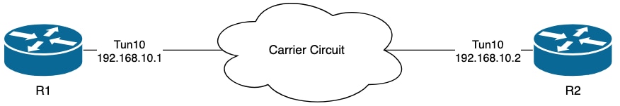
The logs on R1 indicate that there have been intermittent EIGRP flaps which occurred mutliple hours apart from each other:
R1#show logging | i EIGRP
*Jul 16 20:45:08.019: %DUAL-5-NBRCHANGE: EIGRP-IPv4 1: Neighbor 192.168.10.2 (Tunnel10) is down: Interface PEER-TERMINATION received
*Jul 16 20:45:12.919: %DUAL-5-NBRCHANGE: EIGRP-IPv4 1: Neighbor 192.168.10.2 (Tunnel10) is up: new adjacency
*Jul 17 10:25:42.970: %DUAL-5-NBRCHANGE: EIGRP-IPv4 1: Neighbor 192.168.10.2 (Tunnel10) is down: holding time expired
*Jul 17 10:25:59.488: %DUAL-5-NBRCHANGE: EIGRP-IPv4 1: Neighbor 192.168.10.2 (Tunnel10) is up: new adjacency
*Jul 17 14:39:02.970: %DUAL-5-NBRCHANGE: EIGRP-IPv4 1: Neighbor 192.168.10.2 (Tunnel10) is down: holding time expired
*Jul 17 14:39:16.488: %DUAL-5-NBRCHANGE: EIGRP-IPv4 1: Neighbor 192.168.10.2 (Tunnel10) is up: new adjacency
The packet loss could be in both directions; holding time expired indicates that this device did not receive or process a hello from the peer within the hold time, and Interface PEER-TERMINATION received indicates that the peer terminated the adjacency because it did not receive or process a hello within the hold time.
Configuration
1. Configure the ACL with the Tunnel interface IP addresses, as these are the source IP addresses of the hellos:
R1#conf t
R1(config)#ip access-list extended FLAP_CAPTURE
R1(config-ext-nacl)#permit ip host 192.168.10.1 any
R1(config-ext-nacl)#permit ip host 192.168.10.2 any
R1(config-ext-nacl)#end Note: The configurations shown are from R1. The same is done on R2 for the relevant interfaces and with modified file names for the EEM. If additional specificity is required, configure the ACL with EIGRP multicast address 224.0.0.10 as the destination IP address to capture hellos.
2. Create the EPC and associate it with the interface and the ACL:
R1#monitor capture CAP interface Tunnel10 both
R1#monitor capture CAP access-list FLAP_CAPTURE
R1#monitor capture CAP buffer size 5 circular
3. Start the EPC and confirm packets are captured in both directions:
R1#monitor capture CAP start
R1#show monitor capture CAP buffer brief
 ----------------------------------------------------------------------------
 #   size   timestamp     source             destination      dscp    protocol
 ----------------------------------------------------------------------------
   0   74    0.000000   192.168.10.1     ->  224.0.0.10       48 CS6  EIGRP
   1   74    0.228000   192.168.10.2     ->  224.0.0.10       48 CS6  EIGRP
   2   74    4.480978   192.168.10.2     ->  224.0.0.10       48 CS6  EIGRP
   3   74    4.706024   192.168.10.1     ->  224.0.0.10       48 CS6  EIGRP
4. Configure the EEM:
R1#conf t
R1(config)#event manager applet R1_EIGRP_FLAP authorization bypass
R1(config-applet)#event syslog pattern "%DUAL-5-NBRCHANGE" maxrun 120 ratelimit 100000
R1(config-applet)#action 000 cli command "enable"
R1(config-applet)#action 005 cli command "show clock | append bootflash:R1_EIGRP_FLAP.txt"
R1(config-applet)#action 010 cli command "show logging | append bootflash:R1_EIGRP_FLAP.txt"
R1(config-applet)#action 015 cli command "show process cpu sorted | append bootflash:R1_EIGRP_FLAP.txt"
R1(config-applet)#action 020 cli command "show process cpu history | append bootflash:R1_EIGRP_FLAP.txt"
R1(config-applet)#action 025 cli command "show interfaces | append bootflash:R1_EIGRP_FLAP.txt"
R1(config-applet)#action 030 cli command "monitor capture CAP stop"
R1(config-applet)#action 035 cli command "monitor capture CAP export bootflash:R1_EIGRP_CAP.pcap"
R1(config-applet)#action 040 syslog msg "Saved logs to bootflash:R1_EIGRP_FLAP.txt and saved packet capture to bootflash:R1_EIGRP_CAP.pcap"
R1(config-applet)#action 045 cli command "end"
R1(config-applet)#end
5. Wait for the next flap to occur, and copy the files from bootflash via your preferred transfer method for analysis:
R1#show logging
<OMITTED>
*Jul 17 16:51:47.154: %DUAL-5-NBRCHANGE: EIGRP-IPv4 1: Neighbor 192.168.10.2 (Tunnel10) is down: Interface PEER-TERMINATION received
*Jul 17 16:51:48.015: %BUFCAP-6-DISABLE: Capture Point CAP disabled.
*Jul 17 16:51:48.283: %HA_EM-6-LOG: EIGRP_FLAP: Saved logs to bootflash:EIGRP_FLAP.txt and saved packet capture to bootflash:EIGRP_FLAP.pcap
*Jul 17 16:51:51.767: %DUAL-5-NBRCHANGE: EIGRP-IPv4 1: Neighbor 192.168.10.2 (Tunnel10) is up: new adjacency
R1#
R1#dir bootflash: | i EIGRP
23      -rw-           147804  Jul 17 2024 16:51:48 +00:00  EIGRP_CAP.pcap
22 -rw- 74450 Jul 17 2024 16:51:47 +00:00 EIGRP_FLAP.txt- The log buffer on the router indicates that there was an EIGRP flap, and the files have been saved by the EEM.
Analysis
At this point, correlate the time of the flap found in the log buffer with the packet captures that were gathered to determine if the hello packets were sent and received on both ends when the flap occurred. Since Interface PEER-TERMINATION received was seen on R1, this means R2 must have detected lost hellos and therefore holding time expired, which is what is seen in the log file:
*Jul 17 16:51:47.156: %DUAL-5-NBRCHANGE: EIGRP-IPv4 1: Neighbor 192.168.10.1 (Tunnel10) is down: holding time expired
*Jul 17 16:51:51.870: %DUAL-5-NBRCHANGE: EIGRP-IPv4 1: Neighbor 192.168.10.1 (Tunnel10) is up: new adjacency
Because R2 detected holding time expired, confirm whether there were hellos sent by R1 in the 15 seconds before the flap in the capture gathered on R1:
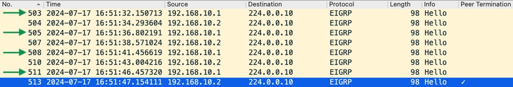
- The capture shows hellos from both 192.168.10.1 (R1) and 192.168.10.2 (R2) in the 15 seconds before the PEER-TERMINATION hello packet that R2 sends at 16:51:47 (packet 513).
- Specifically, packets 503, 505, 508, and 511 (indicated by the green arrows) were all hellos sent by R1 in this time period.
The next step is to confirm whether all of the hellos sent by R1 were received by R2 at the time, so the capture gathered from R2 must be checked:
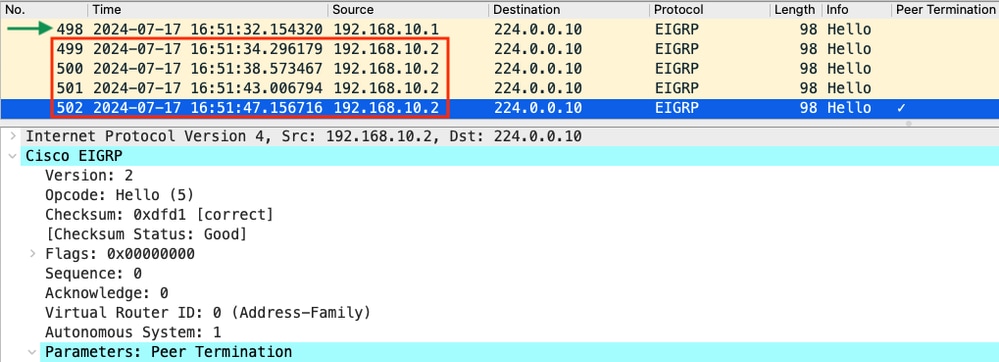
- The capture shows that the last hello received from 192.168.10.1 (R1) was at 16:51:32 (indicated by the green arrow). After this, the next 15 seconds shows only hellos sent by R2 (indicated by the red box). Packets 505, 508, and 511 in the capture from R1 do not appear in the capture on R2. This causes R2 to detect holding timer expired and send the PEER-TERMINATION hello packet at 16:51:47 (packet 502).
The conclusion from this data is that the packet loss is somewhere in the carrier network between R1 and R2. In this instance, the loss was in the direction from R1 to R2. To investigate further, the carrier needs to be involved to check the path for drops.
OSPF
The same logic can be used to troubleshoot intermittent OSPF flaps. This section describes they key factors which distinguish it from other routing protocols with respect to timers, IP address filters, and log messages.
- The default timers are 10-second hellos and a 40-second dead timer. Always confirm the timers that are in use in your network when troubleshooting dead timer expired flaps.
- Hello packets are sourced from the interface IP addresses. If additional ACL specificity is needed, the multicast destination address for OSPF hellos is 224.0.0.5.
- The log messages on the devices are slightly different. Contrary to EIGRP, there is no concept of a peer termination message with OSPF. Rather, the device which detects the expired dead timer logs this as the flap reason and then the hellos it sends no longer contain the router ID of the peer, which causes the peer to move to the INIT state. When the hellos are detected again, the adjacency transitions through until it reaches the FULL state. For example:
R1 detects dead timer expired:
R1#show logging | i OSPF
*Jul 30 15:29:14.027: %OSPF-5-ADJCHG: Process 1, Nbr 192.168.30.2 on Tunnel20 from FULL to DOWN, Neighbor Down: Dead timer expired
*Jul 30 15:32:30.278: %OSPF-5-ADJCHG: Process 1, Nbr 192.168.30.2 on Tunnel20 from LOADING to FULL, Loading Done
*Jul 30 16:33:19.841: %OSPF-5-ADJCHG: Process 1, Nbr 192.168.30.2 on Tunnel20 from FULL to DOWN, Neighbor Down: Dead timer expired
*Jul 30 16:48:10.504: %OSPF-5-ADJCHG: Process 1, Nbr 192.168.30.2 on Tunnel20 from LOADING to FULL, Loading Done
However, R2, only shows the log messages when OSPF moves back to FULL. It does not show a log message when the state changes to INIT:
R2#show logging | i OSPF
*Jul 30 16:32:30.279: %OSPF-5-ADJCHG: Process 1, Nbr 192.168.30.1 on Tunnel20 from LOADING to FULL, Loading Done
*Jul 30 16:48:10.506: %OSPF-5-ADJCHG: Process 1, Nbr 192.168.30.1 on Tunnel20 from LOADING to FULL, Loading Done
To trigger the EEM on both devices, use "%OSPF-5-ADJCHG" as the syslog pattern. This ensures that the EEM triggers on both devices as long as it went down and came back up. The configured ratelimit value ensures that it does not trigger twice within a short period when multiple logs with this string are seen. The key is to confirm whether hellos are sent and received in the packet captures on both sides.
BGP
The same logic can be used to troubleshoot intermittent BGP flaps. This section describes they key factors which distinguish it from other routing protocols with respect to timers, IP address filters, and log messages.
- The default timers are 60-second keepalives and a 180-second hold time. Always confirm the timers that are in use in your network when troubleshooting hold time expired flaps.
- Keepalive packets are sent unicast between the neighbor IP addresses to TCP destination port 179. If additional ACL specificity is needed, permit TCP traffic from the source IP addresses to destination TCP port 179.
- The log messages for BGP look similar on both devices, but the device which detects hold time expires shows that it sent the notification to the neighbor, while the other indicates that it received the notification message. For example:
R1 detects hold time expired and sends the notification to R2:
R1#show logging | i BGP
*Jul 30 17:49:23.730: %BGP-3-NOTIFICATION: sent to neighbor 192.168.30.2 4/0 (hold time expired) 0 bytes
*Jul 30 17:49:23.731: %BGP-5-NBR_RESET: Neighbor 192.168.30.2 reset (BGP Notification sent)
*Jul 30 17:49:23.732: %BGP-5-ADJCHANGE: neighbor 192.168.30.2 Down BGP Notification sent
*Jul 30 17:49:23.732: %BGP_SESSION-5-ADJCHANGE: neighbor 192.168.30.2 IPv4 Unicast topology base removed from session  BGP Notification sent
R2 receives the notification from R1 because R1 detected hold time expired:
R2#show logging | i BGP
*Jul 30 17:49:23.741: %BGP-3-NOTIFICATION: received from neighbor 192.168.30.1 4/0 (hold time expired) 0 bytes
*Jul 30 17:49:23.741: %BGP-5-NBR_RESET: Neighbor 192.168.30.1 reset (BGP Notification received)
*Jul 30 17:49:23.749: %BGP-5-ADJCHANGE: neighbor 192.168.30.1 Down BGP Notification received
*Jul 30 17:49:23.749: %BGP_SESSION-5-ADJCHANGE: neighbor 192.168.30.1 IPv4 Unicast topology base removed from session  BGP Notification received
To trigger the EEM for a BGP flap, use "%BGP_SESSION-5-ADJCHANGE" as the syslog pattern. Any of the other "%BGP" syslog messages that are also logged after the flap can be used to trigger the EEM as well.
Troubleshoot Intermittent BFD Flaps
The same methodology can be applied to troubleshoot intermittent BFD flaps, with some minor differences to apply to the analysis. This section covers some basic BFD functionality and provides an example of how to use EEM and EPC to troubleshoot. For more detailed BFD troubleshooting information, refer to Troubleshoot Bidirectional Forwarding Detection in Cisco IOS XE.
In this example, the BFD timers are set to 300ms with a multiplier of 3, which means echos are sent every 300ms, and an echo failure is detected when 3 echo packets in a row are not returned (equal to a 900ms hold time).
Topology
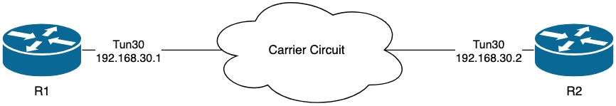
Example - BFD Echo Mode
In BFD Echo Mode (the default mode), the BFD echo packets are sent with the local interface IP as the source and destination. This allows the neighbor to process the packet in the data plane and return it to the source device. Each BFD echo is sent with an echo ID in the BFD Echo Message header. These can be used to determine if a sent BFD echo packet was received back, as there must be two occurrences of any given BFD echo packet if it was indeed returned by the neighbor. The BFD control packets, which are used to control the state of the BFD session, are sent unicast between the interface IP addresses.
The logs from R1 indicate that the BFD adjacency has gone down multiple times due to ECHO FAILURE, which means that during those intervals, R1 did not receive or process 3 of its own echo packets back from R2.
R1#show logging | i BFD
*Jul 18 13:41:09.007: %BFDFSM-6-BFD_SESS_DOWN: BFD-SYSLOG: BFD session ld:4097 handle:1,is going Down Reason: ECHO FAILURE
*Jul 18 13:41:09.009: %BGP-5-NBR_RESET: Neighbor 192.168.30.2 reset (BFD adjacency down)
*Jul 18 13:41:09.010: %BGP-5-ADJCHANGE: neighbor 192.168.30.2 Down BFD adjacency down
*Jul 18 13:41:09.010: %BGP_SESSION-5-ADJCHANGE: neighbor 192.168.30.2 IPv4 Unicast topology base removed from session  BFD adjacency down
*Jul 18 13:41:09.010: %BFD-6-BFD_SESS_DESTROYED: BFD-SYSLOG: bfd_session_destroyed,  ld:4097 neigh proc:BGP, handle:1 active
*Jul 18 13:41:13.335: %BFDFSM-6-BFD_SESS_UP: BFD-SYSLOG: BFD session ld:4097 handle:1 is going UP
*Jul 18 13:41:18.576: %BFD-6-BFD_SESS_CREATED: BFD-SYSLOG: bfd_session_created, neigh 192.168.30.2 proc:BGP, idb:Tunnel30 handle:1 act
*Jul 18 13:41:19.351: %BFDFSM-6-BFD_SESS_UP: BFD-SYSLOG: BFD session ld:4097 handle:1 is going UP
*Jul 18 15:44:08.360: %BFDFSM-6-BFD_SESS_DOWN: BFD-SYSLOG: BFD session ld:4097 handle:1,is going Down Reason: ECHO FAILURE
*Jul 18 15:44:08.362: %BGP-5-NBR_RESET: Neighbor 192.168.30.2 reset (BFD adjacency down)
*Jul 18 15:44:08.363: %BGP-5-ADJCHANGE: neighbor 192.168.30.2 Down BFD adjacency down
*Jul 18 15:44:08.363: %BGP_SESSION-5-ADJCHANGE: neighbor 192.168.30.2 IPv4 Unicast topology base removed from session  BFD adjacency down
*Jul 18 15:44:08.363: %BFD-6-BFD_SESS_DESTROYED: BFD-SYSLOG: bfd_session_destroyed,  ld:4097 neigh proc:BGP, handle:1 active
*Jul 18 15:44:14.416: %BFDFSM-6-BFD_SESS_UP: BFD-SYSLOG: BFD session ld:4097 handle:1 is going UP
*Jul 18 15:44:14.418: %BFD-6-BFD_SESS_DESTROYED: BFD-SYSLOG: bfd_session_destroyed,  ld:4097 neigh proc:CEF, handle:1 active
*Jul 18 15:44:18.315: %BFD-6-BFD_SESS_CREATED: BFD-SYSLOG: bfd_session_created, neigh 192.168.30.2 proc:BGP, idb:Tunnel30 handle:2 act
Configuration
1. Configure the ACL with the Tunnel interface IP addresses, as these are the source IP addresses of the BFD echo packets and control packets:
R1#conf t
R1(config)#ip access-list extended FLAP_CAPTURE
R1(config-ext-nacl)#permit ip host 192.168.30.1 any
R1(config-ext-nacl)#permit ip host 192.168.30.2 any
Note: The configurations shown are from R1. The same is done on R2 for the relevant interfaces and with modified file names for the EEM. If additional specificity is required, configure the ACL for UDP with destination ports 3785 (echo packets) and 3784 (control packets).
2. Create the EPC and associate it with the interface and the ACL:
R1#monitor capture CAP interface Tunnel30 both
R1#monitor capture CAP access-list FLAP_CAPTURE
R1#monitor capture CAP buffer size 5 circular
3. Start the EPC and confirm packets are captured in both directions:
R1#monitor capture CAP start
R1#show monitor capture CAP buff brief
 ----------------------------------------------------------------------------
 #   size   timestamp     source             destination      dscp    protocol
 ----------------------------------------------------------------------------
   0   54    0.000000   192.168.30.2     ->  192.168.30.2     48 CS6  UDP
   1   54    0.000000   192.168.30.2     ->  192.168.30.2     48 CS6  UDP
   2   54    0.005005   192.168.30.1     ->  192.168.30.1     48 CS6  UDP
   3   54    0.005997   192.168.30.1     ->  192.168.30.1     48 CS6  UDP
4. Configure the EEM:
R1#conf t
R1(config)#event manager applet R1_BFD_FLAP authorization bypass
R1(config-applet)#event syslog pattern "%BFDFSM-6-BFD_SESS_DOWN" maxrun 120 ratelimit 100000
R1(config-applet)#action 000 cli command "enable"
R1(config-applet)#action 005 cli command "show clock | append bootflash:R1_BFD_FLAP.txt"
R1(config-applet)#action 010 cli command "show logging | append bootflash:R1_BFD_FLAP.txt"
R1(config-applet)#action 015 cli command "show process cpu sorted | append bootflash:R1_BFD_FLAP.txt"
R1(config-applet)#action 020 cli command "show process cpu history | append bootflash:R1_BFD_FLAP.txt"
R1(config-applet)#action 025 cli command "show interfaces | append bootflash:R1_BFD_FLAP.txt"
R1(config-applet)#action 030 cli command "monitor capture CAP stop"
R1(config-applet)#action 035 cli command "monitor capture CAP export bootflash:R1_BFD_CAP.pcap"
R1(config-applet)#action 040 syslog msg "Saved logs to bootflash:R1_BFD_FLAP.txt and saved packet capture to bootflash:R1_BFD_CAP.pcap"
R1(config-applet)#action 045 cli command "end"
R1(config-applet)#end
5. Wait for the next flap to occur, and copy the files from bootflash via your preferred transfer method for analysis:
R1#show logging
<OMITTED>
*Jul 18 19:09:47.482: %BFDFSM-6-BFD_SESS_DOWN: BFD-SYSLOG: BFD session ld:4097 handle:1,is going Down Reason: ECHO FAILURE
*Jul 18 19:09:47.483: %BGP-5-NBR_RESET: Neighbor 192.168.30.2 reset (BFD adjacency down)
*Jul 18 19:09:47.487: %BGP-5-ADJCHANGE: neighbor 192.168.30.2 Down BFD adjacency down
*Jul 18 19:09:47.487: %BGP_SESSION-5-ADJCHANGE: neighbor 192.168.30.2 IPv4 Unicast topology base removed from session  BFD adjacency down
*Jul 18 19:09:47.487: %BFD-6-BFD_SESS_DESTROYED: BFD-SYSLOG: bfd_session_destroyed,  ld:4097 neigh proc:BGP, handle:1 active
*Jul 18 19:09:48.191: %BUFCAP-6-DISABLE: Capture Point CAP disabled.
*Jul 18 19:09:48.668: %HA_EM-6-LOG: R1_BFD_FLAP: Saved logs to bootflash:R1_BFD_FLAP.txt and saved packet capture to bootflash:R1_BFD_CAP.pcap
*Jul 18 19:09:50.165: %BFDFSM-6-BFD_SESS_UP: BFD-SYSLOG: BFD session ld:4097 handle:1 is going UP
*Jul 18 19:09:54.386: %BFD-6-BFD_SESS_CREATED: BFD-SYSLOG: bfd_session_created, neigh 192.168.30.2 proc:BGP, idb:Tunnel30 handle:1 act
*Jul 18 19:09:54.386: %BGP-5-ADJCHANGE: neighbor 192.168.30.2 Up
*Jul 18 19:09:55.178: %BFDFSM-6-BFD_SESS_UP: BFD-SYSLOG: BFD session ld:4097 handle:1 is going UP
R1#
R1#dir | i BFD
25      -rw-          1591803  Jul 18 2024 19:09:48 +00:00  R1_BFD_CAP.pcap
24 -rw- 84949 Jul 18 2024 19:09:48 +00:00 R1_BFD_FLAP.txt- The log buffer indicates that there was a BFD flap at 19:09:47, and the files have been saved by the EEM.
Analysis
At this point, correlate the time of the flap found in the log buffer with the packet captures that were gathered to determine if the BFD echos were sent and received on both ends when the problem occurred. Since the flap reason on R1 is ECHO FAILURE, this means it would have also sent a control packet to R2 to terminate the BFD session, and this is reflected in the log file gathered from R2 where the BFD down reason RX DOWN is seen:
*Jul 18 19:09:47.468: %BFDFSM-6-BFD_SESS_DOWN: BFD-SYSLOG: BFD session ld:4098 handle:2,is going Down Reason: RX DOWN
*Jul 18 19:09:47.470: %BGP-5-NBR_RESET: Neighbor 192.168.30.1 reset (BFD adjacency down)
*Jul 18 19:09:47.471: %BGP-5-ADJCHANGE: neighbor 192.168.30.1 Down BFD adjacency down
*Jul 18 19:09:47.471: %BGP_SESSION-5-ADJCHANGE: neighbor 192.168.30.1 IPv4 Unicast topology base removed from session  BFD adjacency down
*Jul 18 19:09:47.471: %BFD-6-BFD_SESS_DESTROYED: BFD-SYSLOG: bfd_session_destroyed,  ld:4098 neigh proc:BGP, handle:2 active
Because R1 detected an ECHO FAILURE, check the packet capture gathered on R1 to see whether it sent and received BFD echos in the 900ms before the flap.
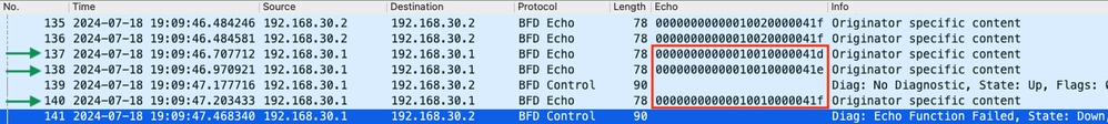
- The capture shows that R1 actively sent BFD echo packets all the way up to the time of the flap, but they were not returned by R2, so R1 sends a control packet to terminate the session at 19:09:47.468.
- This evident from the fact that packets 137, 138, and 140 (indicated by the green arrows) are only seen a single time in the capture, which can be determined from the BFD Echo IDs (in the red box). If the echos had been returned, then there would be a second copy of each of those packets with the same BFD echo ID. The IP Identification field in the IP header (not pictured here) can be used to verify this as well.
- This capture also shows that no BFD echos were received from R2 after packet 136, which is another indication of packet loss in the direction of R2 to R1.
The next step is to confirm whether all of the BFD echo packets sent by R1 were received and returned by R2, so the capture gathered from R2 must be checked:
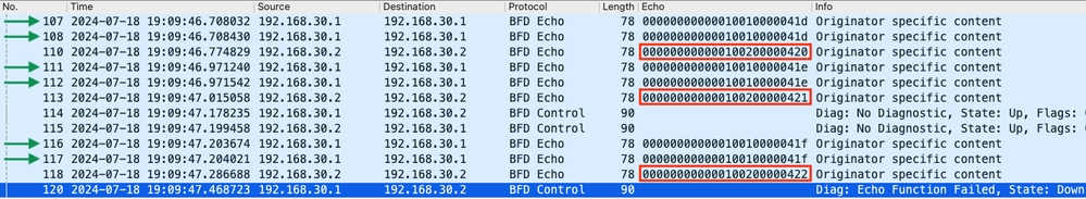
- This capture shows that all of the BFD echos sent by R1 were received and returned by R2 (indicated with green arrows); Packets 107 and 108 are the same BFD echo, packets 111 and 112 are the same BFD echo, and packets 116 and 117 are the same BFD echo.
- This capture also shows that R2 actively sent echo packets (indicated with red boxes) which are not seen in the capture on R1, which further indicates packet loss between the devices in the direction from R2 to R1.
The conclusion from this data is that the packet loss is somewhere in the carrier network between R1 and R2, and all of the evidence at this point indicates that the direction of loss is from R2 to R1. To investigate further, the carrier needs to be involved to check the path for drops.
BFD Asynchronous Mode
The same method can be applied when BFD asynchronous mode is in use (echo function disabled), and the EEM and EPC configuration can be kept the same. The difference in asynchronous mode is that the devices send unicast BFD control packets to each other as keepalives, analogous to a typical routing protocol adjacency. This means that only UDP port 3784 packets are sent. In this scenario, BFD remains in the up state as long as a BFD packet is received from the neighbor within the required interval. When this does not happen, the failure reason is DETECT TIMER EXPIRED, and the router sends a control packet to the peer to bring down the session.
To analyze the captures on the device which detected the failure, look for the unicast BFD packets received from the peer during the time right before to the flap. For example, if the TX interval is set to 300ms with a multiplier of 3, then if there are no BFD packets received in the 900ms prior to the flap, this indicates potential packet loss. In the capture gathered from the neighbor via the EEM, check this same time window; if the packets were sent during that time, then it confirms there is loss somewhere in between the devices.
Revision History
| Revision | Publish Date | Comments |
|---|---|---|
1.0 |
20-Dec-2024 |
Initial Release |
Contributed by Cisco Engineers
- Matt SnowTechnical Consulting Engineer
 Feedback
Contact Cisco
- Open a Support Case

- (Requires a Cisco Service Contract)