Token Ring Switching Concepts
Available Languages
Bias-Free Language
The documentation set for this product strives to use bias-free language. For the purposes of this documentation set, bias-free is defined as language that does not imply discrimination based on age, disability, gender, racial identity, ethnic identity, sexual orientation, socioeconomic status, and intersectionality. Exceptions may be present in the documentation due to language that is hardcoded in the user interfaces of the product software, language used based on RFP documentation, or language that is used by a referenced third-party product. Learn more about how Cisco is using Inclusive Language.
Contents
Introduction
To start to understand the concepts of Token Ring switching, it is very important that you understand transparent bridging, source-route bridging, and Spanning-Tree. The Catalyst 3900 and the Catalyst 5000 use new concepts, as described in IEEE 802.5 annex K. These concepts are the building blocks for Token Ring VLANs. This document explains the different bridging concepts and how these work:
-
Inter-Switch Link (ISL) Trunking
-
Spanning-Tree
-
VLAN Trunking Protocol (VTP)
-
Duplicate Ring Protocol (DRiP)
Prerequisites
Requirements
There are no specific requirements for this document.
Components Used
This document is not restricted to specific software and hardware versions.
The information in this document was created from the devices in a specific lab environment. All of the devices used in this document started with a cleared (default) configuration. If your network is live, make sure that you understand the potential impact of any command.
Conventions
For more information on document conventions, refer to the Cisco Technical Tips Conventions.
TrBRF and TrCRF
Token Ring Bridge Relay Function (TrBRF) and Token Ring Concentrator Relay Function (TrCRF) are the building blocks of the architecture of the Catalyst 3900 and the Catalyst 5000 functionality. TrBRF is simply the bridge function of the switch, and TrCRF is the concentrator function of the switch. It is important to understand that bridging happens at both of these layers because, in Token Ring, three different types of bridging will be discussed.
The TrBRF functionality of the switch controls switching of source-route bridged traffic, like source-route bridging (SRB) and source-route transparent bridging (SRT). The TrCRF covers the functionality of source-route switching (SRS) and transparent bridging (TB). For example, it is possible to have a Catalyst 3900 switch that only has one TrBRF and one TrCRF and all ports of the switch are in the same TrCRF. This causes the switch to only be able to do SRS and TB. If you defined ten different TrCRFs under the same parent TrBRF, then traffic from ports that are connected to the same TrCRF would be forwarded via the TrCRF functionality of SRS or TB. Traffic going to the other TrCRFs in the switch would use the TrBRF functionality of the switch and be either source-route bridged or source-route transparently bridged. The different switching mechanisms will be discussed later in this document.
This diagram relates the TrBRF and the TrCRF to the physical world:
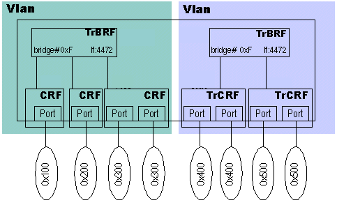
You can see that each TrCRF is connected to one specific ring. A TrCRF can compromise multiple ports, and these ports would compromise the same ring number. The TrBRF connects the TrCRFs together.
A TrCRF and a TrBRF in itself is a different VLAN. So, in Token Ring, you can bridge between VLANs. The bridging between Token Ring VLANs follows two rules:
-
Bridging between two TrBRF VLANs can only be accomplished by an external device, like a router or a Route Switch Module (RSM).
-
Bridging between TrCRF VLANs can only be accomplished with TrCRF VLANs that are children of the same parent TrBRF VLAN.
This is very important to keep in mind for Token Ring VLANs, because it breaks the Ethernet paradigm. To summarize, what would look like an Ethernet VLAN is the sum of one TrBRF and its children TrCRF. Because you can bridge between certain VLANs in Token Ring, you must understand how this bridging occurs.
Note: To make it easier to understand Token Ring VLANs in relation to Ethernet VLANs, remember that the combination of TrCRF and TrBRF makes a VLAN in itself.
In this diagram, you can see that the TrCRF decides the bridging mode between the TrCRF and the TrBRF.
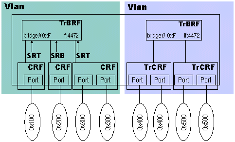
The individual TrCRFs have configured what type of bridging they will be doing to the TrBRF. This is important because you can have TrCRF VLANs that will do source-route bridging to other TrCRFs but will not do non-source-routed frames. In the previous diagram, one TrCRF is configured for SRB mode and two are in SRT mode. This means that SRB traffic can flow between all three TrCRFs, but SRT can only flow between the two that are in SRT mode. This allows you to granularly set how traffic should flow between the TrCRFs. If bridging mode was set at the TrBRF, it would affect all TrCRF children of that VLAN.
Switching Modes
Out of the box, the Catalyst 3900 is configured with one TrBRF and one TrCRF. All ports are assigned to the default TrCRF VLAN 1003. The same applies to the Catalyst 5000 Token Ring blade. This is important because it gives the box certain ???plug-and-play??? functionality. Out of the box, these switches can do forwarding based on source-route switching and transparent bridging. The next sections provide details about these technologies.
Transparent Bridging
Transparent Bridging is the most basic of all switching mechanisms and is based on the destination MAC (DMAC) address of frames in the network. This is the forwarding mechanism of Ethernet networks. Any time a switch receives a frame, it records the source MAC (SMAC) address of the frame as one that belongs to that port and, henceforth, forwards traffic that is destined to that MAC to that port. If, in the learning process, a switch does not know about a MAC address, it will flood that packet to all ports in forwarding state.
Source-Route Switching
Source-route switching is a forwarding mechanism that is needed when there is only one TrCRF assigned to the ports and the switch receives packets with Routing Information Fields (RIFs) in them. Because the switch will not modify the RIF of the frame (because it will not pass it to the TrBRF), the network must be able to make decisions on forwarding, with the RIF, without modifications. Consider this network diagram that shows SRS:
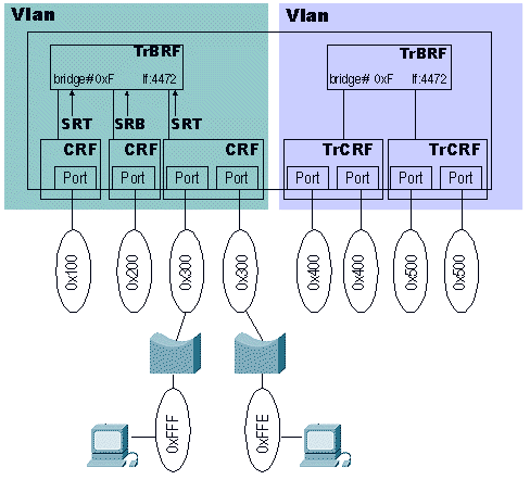
The traffic going from ring 0xFFF to ring 0xFFE needs to go through the switch. This traffic would be source-route bridge traffic. This is the communication startup sequence between these two clients:
-
One station sends an explorer packet to the ring on which it resides. Assume that the client on ring 0xFFF sends the packet; it looks something like this (in hexadecimal):
0000 00c1 2345 8000 0c11 1111 C270
Note: That packet information only shows DMAC, SMAC, and RIF information.
-
Once the packet reaches the source-route bridge and forwards the frame to the wire, the packet looks like this:
0000 00C1 2345 8000 0c11 1111 C670 FFF1 3000
C670 is the routing control field and FFF1 3000 is ring 0xFFF, bridge 0x1, ring 0x300.
-
Now, the packet hits the switch. Because the switch sees the packet coming from a far away ring, it learns the route descriptor. In this case, the switch now knows that ring 0xFFF via bridge 0x1 is located on port 3.
-
Because the packet is an explorer packet, the switch forwards the frame to all of the ports under the same TrCRF. If the explorer needs to go to ports in different TrCRFs, it will deliver the frame to the TrBRF, which will do its bridge functionality. If there are ports in the same TrCRF, it will forward the frame outbound without modification.
-
The station in ring 0xFFE should get the explorer and respond to it. Assume that the client responds with a directed frame. This directed frame looks like this:
0000 0C11 1111 8000 00C1 2345 08E0 FFF1 3001 FFE0
08E0 is the routing control field and FFF1 3001 FFE0 is ring 0xFFF, bridge 0x1, ring 0x300, bridge 0x1, ring 0xFFE.
-
Finally, the switch learns that ring 0xFFE is located on port 4 and keeps the route descriptor.
Henceforth, the switch knows about those rings. If you look at the tables, you should see that the switch has learned about the bridge number and the ring number. Any other rings after ring 0xFFF and ring 0xFFE are not necessary, because they have to pass through either ring 0xFFF or ring 0xFFE to reach the switch.
SRS is a basic forwarding of RIF-based packets without SRB functionality, as is the case with the TrCRF.
Note: To view the routing information table in the Catalyst 5000, issue the show rif command.
Source-Route Bridging and Source-Route Transparent
All of the source-route bridging functionality is located in the TrBRF logic. The TrCRF is the one that is going to command the bridging mode to the TrBRF. So, if the TrCRF is configured for SRB mode to the TrBRF then, when the TrCRF receives an NSR (non-source-routed) frame, the switch will not forward it to the TrBRF logic.
This can be used if you do not want certain types of traffic to hit or leave a specific ring. This diagram shows an example:
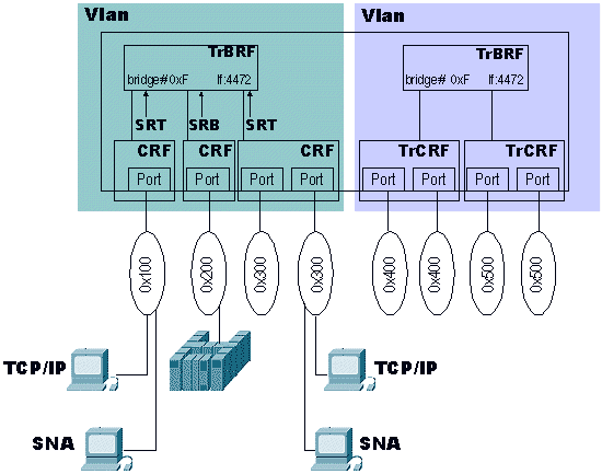
If the TCP/IP clients did not have the ability to send packets with RIFs, the switch would not put those frames in the same ring with the mainframe (0x200). However, the SNA frames to the host (which usually do have a RIF) would reach the mainframe. This is a very rudimentary way to filter frames in a switched network.
This is the sequence that the switch follows to forward a source-route bridged frame across the TrBRF:
-
The SNA station on ring 0x300 (port 4) sends an explorer to reach the mainframe.
-
When the explorer packet hits the switch, it forwards the explorer, without modification, in the same TrCRF; then it sends a copy to the TrBRF to forward to the rest of the TrCRFs. In this case, because the packet has a RIF, it goes through the SRB path. The switch also needs to learn the route.
-
The switch is going to learn the SMAC of the frame, because the packet shows as originating on the local ring to which the switch is connected. This is because, in a multiple port TrCRF combination, the RIF shows the destination ring, but the switch needs to know which port in the TrCRF. Therefore, the switch learns the SMAC of the frames that are coming in at the TrCRF level.
-
The packet goes out to all of the rest of the TrCRFs, modified with their respective bridge ring number combinations.
-
Once the host responds with the SRB frame, the switch learns the SMAC of the host for that TrCRF and sends it to the outbound port. Traffic then flows back and forth between the two.
Note: To check the MAC address table on the Catalyst 5000, issue the show cam command.
Inter-Switch Link
Inter-Switch Link is a very simple protocol. Basically, frames that are going across an ISL trunk are encapsulated in an ISL frame that tells the other side to which VLAN the frames belong. Because of this, VLAN information must be shared either manually or automatically between the switches. A protocol known as VLAN Trunking Protocol (VTP) can handle this task. For Token Ring VLANs, you must run VTP V2 in the network. Consider this diagram:
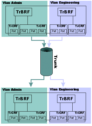
In this case, a single ISL trunk has been created to carry, by itself, the engineering VLANs and the admin VLANs. None of the traffic in either VLAN mixes after it goes through the trunk. This diagram shows the way that this separation is achieved:
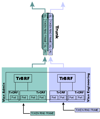
Each frame from those VLANs that needs to go across the trunk is encapsulated in an ISL frame and its VLAN is included in the frame. This allows the receiving switch to correctly route the frame to its specific VLAN. The Token Ring ISL (TRISL) frame has a few more fields than a regular ISL frame. This diagram shows the layout of a TRISL frame:
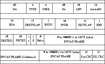
Note: Even though TRISL runs over Fast Ethernet interfaces, the packets contain a standard Token Ring frame and the VLAN information associated with that frame, to a certain extent. Token Ring VLANs permit up to 18k frame sizes, as does ISL. This is not achieved through the fragmentation of the frame. The whole frame is encapsulated in an ISL frame in a whole piece and sent across the link. There is a common misconception that ISL is Ethernet and that its maximum frame size is 1500 bytes.
On Catalyst 5000, a protocol known as Dynamic Trunking Protocol (DTP) became available in release 4.x. DTP is the strategic replacement for Dynamic ISL (DISL) because it incorporates support for 802.1Q trunking negotiation. DISL???s function is to negotiate, for ISL only, whether or not a link between two devices should be trunking. DTP is able to negotiate the kind of trunking encapsulation that will be used between ISL and IEEE 802.1Q VLAN trunks. This is an interesting feature, as some Cisco devices support only ISL or 802.1Q, whereas some are able to run both.
These are the five different states for which you can configure DTP:
-
Auto - In the Auto mode, the port listens for DTP frames from the neighboring switch. If the neighboring switch indicates that it would like to be a trunk - or it is a trunk - then the Auto mode creates the trunk with the neighboring switch. This happens when the neighboring port is set to On or Desirable mode.
-
Desirable - The Desirable mode indicates to the neighboring switch that it is can be an ISL trunk and that it would like the neighboring switch to also be an ISL trunk. The port becomes a trunk port if the neighboring port is set to On, Desirable, or Auto mode.
-
On - The On mode automatically enables ISL trunking on its port, regardless of the state of its neighboring switch. It remains an ISL trunk, unless it receives an ISL packet that explicitly disables the ISL trunk.
-
Nonegotiate - The Nonegotiate mode automatically enables ISL trunking on its port - regardless of the state of its neighboring switch - but does not allow the port to generate DTP frames.
-
Off - In Off mode, ISL is not allowed on this port regardless of the DTP mode that is configured on the other switch.
The Catalyst 5000 family of switches is typically used to provide the ISL backbone. The Catalyst 3900 switch can then be connected to this backbone via the dual 100 Mbps ISL expansion module. The Catalyst 3900 Token Ring switch does not support any other mode than ISL, so it is always trunked. Also, the Catalyst 3900 ISL modules only support 100 Mbps connections and default to full duplex.
Be very careful when you connect a Catalyst 3900 and a Catalyst 5000 switch via the ISL link. The main problem is that the Catalyst 3900 does not support Fast Ethernet media negotiation. For this reason, if the Catalyst 5000 is configured for Auto mode, then it defaults to 100 Mbps half-duplex. This causes problems like the port going from trunk to non-trunk and packet loss.
If you want to attach the Catalyst 3900 ISL port to the ISL port of a Catalyst 5000, you must manually configure the ISL port on the Catalyst 5000:
-
Issue the set port speed command to set to 100 Mbps:
set port speed mod/port {4 | 10 | 16 | 100 | auto}
-
Issue the set port duplex command to set to full duplex:
set port duplex mod/port {full | half}
If you want to force the port of a switch to trunk mode, issue the set trunk command (on one line):
set trunk mod/port {on | off | desirable | auto | nonegotiate}
          [vlans] [trunk_type]
In the previous command, vlans is a value from 1 through 1005 (for example, 2-10 or 1005) and trunk_type is set to isl, dot1q, dot10, lane, or negotiate.
Once the trunk ports are active on the switches, you can issue the show trunk command to see that these trunked ports are active.
Pteradactyl-Sup> (enable) show trunk

Port      Mode         Encapsulation  Status        Native vlan
--------  -----------  -------------  ------------  -----------
 5/1      on           isl            trunking      1
10/1      on           isl            trunking      1

Port      Vlans allowed on trunk
--------  -------------------------------------------------------------------
 5/1      1-1005
10/1      1-1005

Port      Vlans allowed and active in management domain
--------  -------------------------------------------------------------------
 5/1
10/1      1

Port      Vlans in spanning tree forwarding state and not pruned
--------  -------------------------------------------------------------------
 5/1
10/1      1
An important command to use to observe ISL trunks is the show cdp neighbors detail command. This command also helps you understand the network topology.
Pteradactyl-Sup> (enable) show cdp neighbors detail

Port (Our Port): 10/1
Device-ID: 000577:02C700
Device Addresses:
Holdtime: 164 sec
Capabilities: SR_BRIDGE SWITCH
Version:
  Cisco Catalyst 3900 HW Rev 002; SW Rev 4.1(1)
  (c) Copyright Cisco Systems, Inc., 1995-1999  - All rights reserved.
  8 Megabytes System Memory
  2 Megabytes Network memory
Platform: CAT3900
Port-ID (Port on Neighbors's Device): 1/21
VTP Management Domain: unknown
Native VLAN: unknown
Duplex: unknown
From that output, you can clearly see that a Catalyst 3900 is connected to port 10/1. When you inspect port 10/1 in the output of the previous show trunk command, you can tell that it is a trunk port.
Spanning-Tree
Spanning-Tree in Token Ring environments can get very complicated because one can simultaneously run a total of three different Spanning-Tree protocols. For example, a typical environment runs IBM Spanning-Tree at the TrBRF level and runs IEEE (802.1d) or Cisco at the TrCRF level. Therefore, Spanning-Tree is a little more complicated to troubleshoot.
This table tells you what happens based on the different types of possible configurations:
| TrCRF Bridging Mode | TrCRF | TrBRF |
|---|---|---|
| SRB | Runs the IEEE Spanning-Tree. | Performs as a source-route bridge. |
| Processes IBM Spanning-Tree protocol Bridge Protocol Data Units (BPDUs) from external bridges. | Runs the IBM Spanning- Tree protocols to external bridges. | |
| Drops transparent IEEE Spanning-Tree protocol BPDUs of the TrCRF. | ||
| SRT | Runs the Cisco Spanning-Tree protocol. | Performs as a source-route transparent bridge. |
| Replaces bridge group address of destination address field with a Cisco-specific group address, so that external bridges do not analyze TrCRF BPDUs. | Forwards transparent and source-route traffic. | |
| Generate BPDUs, with the RIF bit set in the source address field in the outbound frame and a 2 byte RIF added. This frame format ensures that the TrCRF remains local to the logical ring and is not transparently bridged or source routed to other LANs. Only TrCRFs connected via physical loops receive the BPDUs. | Forwards source-route traffic to all other TrCRFs in the TrBRF, whether they be in SRT or SRB mode. | |
| Process IEEE Spanning-Tree BPDUs from external bridges. | ||
VLAN Trunking Protocol
Because, with ISL, the VLAN determines where a packet should go, it is important that each switch knows about the VLANs in the network. VTP???s purpose in life is to propagate VLAN information across switches. VTP does not run in routers, because they should terminate the VLAN network. Each switch in the network should run VTP. If not, then the switch usually only runs one VLAN (usually VLAN 1) and would not run ISL on that link, because there is no need. VTP makes the creation of VLANs a much easier task, because you could configure the VLANs in one switch and they would propagate through the network. Of course, that comes with problems.
VTP is not a robust system, like the Enhanced Interior Gateway Routing Protocol (EIGRP) or the Open Shortest Path First (OSPF) routing protocol. It is much more simple and operates on a very important concept: revisions. In VTP, there are three types of VTP devices: clients, servers, and transparent devices. Client VTP devices basically just accept VLAN information from server devices and can not modify this information. Servers, however, can modify VTP information on any of the VTP servers. For this reason, VTP has a revision system. Any VTP server that modifies or updates the VLAN database claims that it is the latest revision. For this reason, extreme caution must be used, because the switch with the highest revision will ???win??? and its VLAN information will be the valid one. For example, if you modify one VTP server to say that TrBRF VLAN 100 is going to do IEEE spanning-tree, this would cause havoc among all of the switches, because it could cause switches (like the Catalyst 3900) to put ports in blocking mode, to protect themselves against loops. Also, be careful when you introduce new switches into the network, because they could have higher VTP revisions. In transparent mode, VTP packets received on one trunk are automatically propagated, without changes, to all other trunks on the device; but, they are ignored on the device itself.
When you set up VTP with Token Ring switches, you must run VTP V2. If you are going to have switches that run both Ethernet and Token Ring VLANs, then you must upgrade VTP, even for the Ethernet VLANs. You can not have two different VTP domains (for example, you can not have one for Ethernet and one for Token Ring).
VTP Pruning
One problem with VLAN trunking is that broadcast information from one VLAN propagates across all trunks, because the switches do not know which VLANs exist in a remote switch. VTP pruning was created for this reason. It permits switches to negotiate which VLANs are assigned to ports at the other end of a trunk and, therefore, to prune the VLANs that are not assigned remotely. Pruning is disabled by default on Catalyst 3900 and Catalyst 5000 switches.
Note: VTP pruning is supported on the Catalyst 3900 switch in Release 4.1(1).
Each of the VTP pruning messages contains information about the VLANs in question and contains a bit that indicates whether or not this VLAN should be pruned for this trunk (a 1 indicates that it should not be pruned). With pruning enabled, VLAN traffic is not normally sent across the trunk link, unless the trunk link receives an appropriate join message with the corresponding VLAN???s bit enabled. This is very important because it tells you that, when you use VTP pruning, you must make sure that the correct information and configuration exists and that all switches are running pruning; if a switch does not send join messages to another switch across the trunk, it could get shut off for a particular VLAN or VLANs. When pruning negotiation is complete, the VLAN will finish either in prune or joined state for that trunk.
One very important feature of VTP pruning allows you to configure a VLAN to be pruning eligible or not. This feature tells the switches that are running VTP pruning to not prune this VLAN. When you enable VTP pruning, VLANs 2 through 1000 are pruning eligible VLANs by default. So, when you turn on pruning, it affects all VLANs by default. VLAN 1, the default TrCRF (1003), the default TrBRF (1005), and TrCRFs are always pruning-ineligible; therefore, traffic from these VLANs can not be pruned.
Duplicate Ring Protocol
Duplicate Ring Protocol is designed to run on switches that run Token Ring VLANs. Its job is to ensure the proper configuration of Token Ring VLANs and to create explorer reduction. DRiP uses VTP to synchronize its VLAN database information, but it is not required for DRiP to work (the VLAN database can be established manually). One misconception is that DRiP understands ring numbers; this is not true. DRiP relies on the uniqueness of the VLANs configured in a network and that VLAN database configuration.
One of the most important features of DRiP is to enforce TrCRF distribution. In the Token Ring world, it is very dangerous to distribute any VLAN other than 1003, because of spanning issues. For this reason, if a TrCRF other than VLAN 1003 is distributed, all ports to which that VLAN is associated are disabled by DRiP.
This example illustrates this concept:
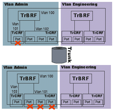
In that example, two different switches have a port that is assigned to VLAN 101. The switch, via DRiP, moves the port spanning-tree to disable and stops forwarding traffic. This safeguards the switch against a possible loop condition.
If there is no change, DRiP advertises the TrCRF status to all of its trunk ports every 30 seconds. Any change done through the CLI (Command Line Interface) or SNMP would immediately send an update to all ports. These advertisements are type 0 ISL frames and flow on the default VLAN 1. Because DRiP only advertises its effects for VLANs, it is important that the correct VLAN information exists in the switches that are connected via ISL. This is done via VTP. If VTP is disabled, then this function must be maintained manually across all of the switches that share the same VLANs. DRiP advertisements only exist on ISL links. They do not exist on ATM, Token Ring, Ethernet, or FDDI. There are no topology trees kept in DRiP.
HSRP and Token Ring VLANs
One of the biggest problems with HSRP is the use of the multicast address in the network. Because nobody in the network actually sources packets with this virtual MAC address, the switches never learn these MAC addresses. Therefore, they flood frames throughout the network. Because of this, the use of the standby use-bia function of HSRP was required to send packets that used the burned-in MAC address of the active HSRP router interface. The main problem with this scenario is that, when the HSRP routers switch, they would have to send a broadcast Address Resolution Protocol (ARP; gratuitous ARP) to all stations on the wire, so that the stations learn the new MAC address of the gateway. Even though this process should work based on IP specifications, there have been some known issues with it. Because of continued requests from the field, HSRP was changed so that you can have the multicast address and also be able to use HSRP without standby use-bia. This change was released in Cisco IOS Software Release 11.3(7) and 12.0(3) and later.
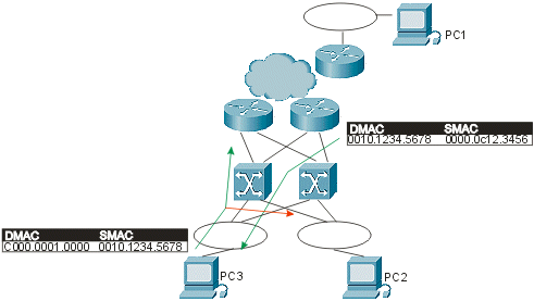
In the previous diagram, communication is occurring between PC1 and PC3. The problem is that the IP traffic from the client to the default router in this picture uses a multicast destination address. Because nobody can source this packet from that address, the switches never learn this address and always flood the packets. The traditional DMAC that depends on the groups is C000.000X.0000, which can never be an SMAC in Token Ring. So all packets destined from PC3 to PC1 via the default gateway are now seen by PC2. In a network with a lot of bridges, this can multiply very rapidly and cause what would seem like broadcast storms but what is actually a large amount of multicast traffic.
To overcome this problem, you must use a MAC address that can actually be used as an SMAC by the routers in the HSRP hellos. This allows the switches to learn this address and, therefore, switch the packets appropriately. To do this, configure a new virtual MAC address in the routers. Clients need to send packets to the DMAC of this new virtual address. This is example output from a show standby command:
vdtl-rsm# show standby

Vlan500 - Group 10
Local state is Active, priority 100
Hellotime 3 holdtime 10
Next hello sent in 00:00:01.224
Hot standby IP address is 1.1.1.100 configured
Active router is local
Standby router is unknown expired
Standby virtual mac address is 0000.0c07.ac0a
In that output, a standby group 10 (standby IP 1.1.1.100) has been created. The MAC address (0000.0c07.ac0a) is the new virtual MAC address and the last byte is the group (0xA = 10). Once you have this new configuration, you would now have this traffic pattern, which avoids traffic floods:
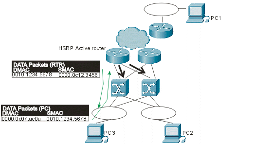
Now, because the router is sourcing packets with the DMAC of the HSRP virtual MAC, the switches learn this MAC address and only forward the packets to the active HSRP router. If the active HSRP router fails and the standby goes active, the new active router will begin to send HSRP hellos with the same SMAC, which causes the switch MAC address tables to switch their learned entries over to the new switch port and trunk.
Because of multiring, additional operation needs to take effect to ensure that the RIF actually changes during the transition (even though it is the same MAC address). Multiring is the capability of the router to associate a RIF with a MAC address, just like an end station. The routers need multiring in environments where SRB bridges exist, so that packets may traverse them to reach end stations.
In the same example as before, you can see the additional steps required for the client to connect to the new active HSRP router:
-
The active router stops working.
-
Once the standby router detects loss of HSRP hellos, it initiates the process to become the active HSRP router.
-
The router sends out a gratuitous ARP from the same SMAC as before, in both of the MAC layers and in the ARP layer.
-
The PC now sends the frame destined to the same MAC address, but with the new RIF.
-
Once the router receives this frame (destined to the HSRP MAC), it sends an ARP request to the client directly, because it does not have the MAC address of that client in its ARP table.
-
Once response to the ARP packet is received, the router can send packets to the destination client.
Related Information
Revision History
| Revision | Publish Date | Comments |
|---|---|---|
1.0 |
09-Oct-2020 |
Initial Release |
 Feedback