Enabling the Catalyst Web Interface on Catalyst 4500/4000 Series Switches Running CatOS
Available Languages
Contents
Introduction
The Cisco Catalyst 4500/4000 series switches that run Catalyst OS (CatOS) software support web-based administration. The Catalyst Web Interface (CWI) is a web browser-based tool that enables this type of administration. The tool is available for the entire line of Catalyst 4500/4000 series switches. By default, the separate CWI software image is not present in Flash memory. You must install the software image separately. This document describes the procedures to install and configure the CWI feature on Catalyst 4500/4000 series switches. This document also describes the switch and browser requirements and the procedures to access CWI on the client.
Note: Catalyst 4500/4000 series switches that run Cisco IOS® system software do not support web interfaces at this time.
Prerequisites
Requirements
This section lists all the hardware and software versions that are supported when you use the CWI.
-
Platforms
-
Catalyst 4500/4000 series Supervisor Engine I
-
Catalyst 4500/4000 series Supervisor Engine II
-
Catalyst 2948G, 2980G, and 4912G
-
-
Web Browsers
-
Internet Explorer, version 5.0 or later
-
Netscape Navigator, version 4.61 or later
Note: On the basis of the version of CiscoView that you run, you must install one of these Java Plug-Ins (JPIs) on your client:
-
CiscoView 5.4(2) through 5.5(3)—Use JPI 1.2.2.
-
CiscoView 5.5(4) and later—Use JPI 1.3.
-
-
-
Memory Requirements
-
DRAM—You do not need a significant amount for the HTTP server. Usage and performance impact depend on the number of concurrent HTTP sessions. The switch supports a maximum of three concurrent HTTP sessions.
-
Flash—Up to 3.5 MB for the Catalyst CiscoView file, in addition to the switch image, is necessary. You need 40 KB for the HTTP server in addition to the switch image.
-
NVRAM—You do not need a significant amount for the CWI.
-
Components Used
The information in this document is based on these software and hardware versions:
-
Catalyst 4000
-
CatOS 5.5(8)
The information in this document was created from the devices in a specific lab environment. All of the devices used in this document started with a cleared (default) configuration. If your network is live, make sure that you understand the potential impact of any command.
Conventions
Refer to Cisco Technical Tips Conventions for more information on document conventions.
Background Information
This section provides an overview of the CWI. You can use the CWI to configure Catalyst 4500/4000 series switches. The tool consists of:
-
A GUI with the name Catalyst CiscoView that runs on the client
-
An HTTP server that runs on the switch
The CiscoView image is not integrated into the CatOS image. You must download and copy the CiscoView image into the Flash file system, in addition to the bootable image.
Both the regular and CiscoView images use similar naming conventions. But the CiscoView image includes a "cv" in the image name to distinguish the image. For example, the version 5.5.8 image can have the name cat4000.5-5-8.bin, while the name of the CWI image would be cat4000-cv.5-5-8.bin.
Note: The CiscoView images are not released with every system image release. Use the CiscoView image that is in the same release train as the system image. For example, use the CiscoView image 6.3(2a) if your system image is 6.3.x. The 6.3(2a) image is the latest CiscoView image in the 6.3 software release train.
The CWI provides a real-time graphical representation of the switch. The CWI also provides details such as:
-
Port status
-
Module status
-
Chassis type
-
Modules
The CWI uses HTTP in order to download CiscoView from the server to the client. In the default state, the HTTP server is disabled. You must enable the HTTP server in order to enable the CWI. After you enable the HTTP server, the server listens to requests on port number 80 by default. You can change the TCP/IP port number to any port number from 1 to 65,535.
After a successful download, CiscoView opens and displays switch information in your browser. The CWI obtains this information from the switch with the use of Simple Network Management Protocol (SNMP) requests.
Verify That You Have the Web Interface Software
Both the boot image and the separate CiscoView image must be present in Flash memory in order to enable the CWI feature.
Note: Use the same software code version for both the boot image and the CiscoView image.
-
Verify that there is space available for both images to reside in the Flash file system.
Issue the dir bootflash: command in order to verify. Here is an example:
cat4000 (enable) dir bootflash:
-#- -length- -----date/time------ name
  1  3651336 May 16 2001 14:30:39 cat4000.5-5-8.bin
  2  2580656 Oct 09 2001 11:22:20 cat4000-cv.5-5-8.bin

9365320 bytes available (6232248 bytes used)
cat4000 (enable)
-
Proceed to the appropriate section of this document:
-
If you find that both images are not present in bootflash, go to Download Software to Flash and Upgrade the Boot Image.
-
If you find that both images are present, go to Configure the HTTP Server.
Note: For more information on how to work with the system files, refer to Working With the Flash File System.
-
Download Software to Flash and Upgrade the Boot Image
If the separate CiscoView image is not already in bootflash, copy the image to the Flash file system on the switch. Choose one of these two options:
-
Download only the CiscoView image if you already have the corresponding boot image of the same version. Proceed to Step 8 of the procedure in this section.
or
-
If you do not have the corresponding boot image, download both the boot image and the corresponding CiscoView image. Proceed to Step 1 of the procedure in this section.
-
Download the image files from Software Download - Cisco Catalyst 4500/4000 CatOS System Software
 (registered customers only) .
 -
Copy the boot images to the TFTP server of your choice.
Put the boot image file in the appropriate TFTP directory on the workstation.
Note: Download a TFTP server. There are many TFTP servers available. Search for "tftp server" on an Internet search engine. Cisco does not specifically recommend a particular TFTP implementation.
-
Log in to the switch through the console port or through a Telnet session.
If you log in with Telnet, your Telnet session disconnects when you reset the switch to run the new software.
-
Issue the copy tftp flash command in order to download the software image from the TFTP server.
At the prompt, enter the IP address or host name of the TFTP server and the name of the file to download. Use "bootflash" as the Flash device to which to copy when you are prompted. You can then copy the file to the default name or modify the destination file name.
The switch downloads the image file from the TFTP server, and the image is copied to the bootflash.
-
Use the set boot system flash bootflash:filename prepend command in order to modify the BOOT environment variable so that the new image boots when you reset the switch.
Specify the file name of the image that you downloaded in the command syntax.
Note: This step is necessary only for the bootable image, not the CiscoView image. The CiscoView image is not a bootable image.
-
Issue the reset system command in order to reset the switch.
This action disconnects your Telnet session, if you use Telnet to connect to the switch.
-
After reboot, issue the show version command in order to check the version of the software on the switch.
-
Copy the CiscoView image file to the appropriate TFTP directory on the workstation.
-
Log in to the switch through the console port or through a Telnet session.
If you log in with Telnet, your Telnet session disconnects when you reset the switch to run the new software.
-
Issue the copy tftp flash command in order to download the CiscoView image from the TFTP server.
At the prompt, enter the IP address or host name of the TFTP server and the name of the file to download. Use "bootflash" as the Flash device to which to copy when you are prompted. You can then copy the file to the default name or modify the destination file name.
The switch downloads the CiscoView image file from the TFTP server, and the image is copied to the bootflash.
-
Issue the dir bootflash: command in order to verify that the CiscoView image downloaded successfully.
cat4000 (enable) dir bootflash:
-#- -length- -----date/time------ name
  1  3651336 May 16 2001 14:30:39 cat4000.5-5-8.bin
  2  2580656 Oct 09 2001 11:22:20 cat4000-cv.5-5-8.bin

9365320 bytes available (6232248 bytes used)
cat4000 (enable)
Example of a Boot Image Upgrade via TFTP
The example in this section shows output from the switch during a TFTP upgrade. The example demonstrates the Download Software to Flash and Upgrade the Boot Image procedure.
Note: For more information on how to upgrade software images, refer to Working with System Software Images.
Console> (enable) copy tftp flash

IP address or name of remote host []? 172.20.52.3

Name of file to copy from []? cat4000.6-1-1.bin

Flash device [bootflash]?
Name of file to copy to [cat4000.6-1-1.bin]?

4369664 bytes available on device bootflash, proceed (y/n) [n]? y

CCCCCCCCCCCCCCCCCCCCCCCCCCCCCCCCCCCCCCCCCCCCCCCCCCCCCCCCCCCCCCCCCCCCCCCCCCCCCCCC
CCCCCCCCCCCCCCCCCCC
File has been copied successfully.
Console> (enable) set boot system flash bootflash:cat4000.6-1-1.bin prepend

BOOT variable = bootflash:cat4000.6-1-1.bin,1;bootflash:cat4000.4-1-2.bin,1;
Console> (enable) reset system

This command will reset the system.
Do you want to continue (y/n) [n]? y

Console> (enable) 07/21/2000,13:51:39:SYS-5:System reset from Console//

System Bootstrap, Version 3.1(2)
Copyright (c) 1994-1997 by cisco Systems, Inc.
Presto processor with 32768 Kbytes of main memory

Autoboot executing command: "boot bootflash:cat4000.6-1-1.bin"
CCCCCCCCCCCCCCCCCCCCCCCCCCCCCCCCCCCCCCCCCCCCCCCCCCCCCCCCCCCCCCCCCCCCCCCCCCCCCCCC
CCCCCCCCCCCCCCCCCCC
Uncompressing file:  ###########################################################
################################################################################
################################################################################
################################################################################
################################################################################
################################################################################
################################################################################
################################################################################
################################################################################
################################################################################
#############

System Power On Diagnostics
NVRAM Size .. .................512KB
ID Prom Test ..................Passed
DPRAM Size ....................16KB
DPRAM Data 0x55 Test ..........Passed
DPRAM Data 0xaa Test ..........Passed
DPRAM Address Test ............Passed
Clearing DPRAM ................Done
System DRAM Memory Size .......32MB
DRAM Data 0x55 Test ...........Passed
DRAM Data 0xaa Test ...........Passed
DRAM Address Test  ............Passed
Clearing DRAM .................Done
EARL++ ........................Present
EARL RAM Test .................Passed
EARL Serial Prom Test .........Passed
Level2 Cache ..................Present
Level2 Cache test..............Passed

Boot image: bootflash:cat4000.6-1-1.bin


Cisco Systems Console


Enter password:
07/21/2000,13:52:51:SYS-5:Module 1 is online
07/21/2000,13:53:11:SYS-5:Module 4 is online
07/21/2000,13:53:11:SYS-5:Module 5 is online
07/21/2000,13:53:14:PAGP-5:Port 1/1 joined bridge port 1/1.
07/21/2000,13:53:14:PAGP-5:Port 1/2 joined bridge port 1/2.
07/21/2000,13:53:40:SYS-5:Module 2 is online
07/21/2000,13:53:45:SYS-5:Module 3 is online

Console> show version 1

Mod Port Model      Serial #              Versions
--- ---- ---------- -------------------- ---------------------------------
1   0    WS-X4012   JAB03130104          Hw : 1.5
                                         Gsp: 6.1(1.4)
                                         Nmp: 6.1(1)
Console>
Configure the HTTP Server
After you have verified that the CWI image is in bootflash, you can configure the HTTP server on the switch. The task has these subtasks:
Enable the HTTP Server
In the default state, the HTTP server is disabled on the switch. In order to enable or disable the HTTP server, issue this command in privileged mode:
set ip http server {enable | disable}
This example enables the server:
Console> (enable) set ip http server enable

HTTP server is enabled on the system.
This example disables the server:
Console> (enable) set ip http server disable

HTTP server is disabled on the system.
Configure the HTTP Port
You do not need to configure the HTTP port unless you want to change the default setting of TCP/IP port 80. In order to configure the port number for the HTTP server, issue this command in privileged mode:
set ip http port {port_number | default}
This example configures a TCP port number other than the default of 80:
Note: This example uses a TCP port number of 2398.
Console> (enable) set ip http port 2398

HTTP TCP port number set to 2398.
This example sets the TCP port number to the default of 80:
Console> (enable) set ip http port default

HTTP TCP port number set to 80.
Display the HTTP Server Information
In order to display the HTTP server information, issue this command in normal mode:
show ip http
This example shows how to view information on the HTTP server. The example also shows that the CWI feature is supported:
cat4000 (enable) show ip http
HTTP Information
----------------------
HTTP server:           enabled
HTTP port:             80
Web Interface:         Supported
Web Interface version(s):
           Engine: 5.2 ADP device: Cat4000 ADP Version: 1.4 ADK: 37a

HTTP active sessions: 0
Display the CWI Version Number
In order to display the CWI version number, issue this command in normal mode:
show version
This example displays the CWI version number:
Console> show version
cat4000 (enable) show version
WS-C4006 Software, Version NmpSW: 5.5(8)
Copyright (c) 1995-2001 by Cisco Systems, Inc.
NMP S/W compiled on May 15 2001, 15:51:27
GSP S/W compiled on May 15 2001, 14:14:47
System Bootstrap Version: 5.4(1)
Hardware Version: 1.2  Model: WS-C4006  Serial #: JAB043300MG

Mod Port Model      Serial #              Versions
--- ---- ---------- -------------------- ---------------------------------
1   2    WS-X4013   JAB043300MG          Hw : 1.2
                                         Gsp: 5.5(8.0)
                                         Nmp: 5.5(8)
2   34   WS-X4232-GB-RJ JAE042921NV          Hw : 2.3

       DRAM                    FLASH                   NVRAM
Module Total   Used    Free    Total   Used    Free    Total Used  Free
------ ------- ------- ------- ------- ------- ------- ----- ----- -----
1       65536K  30015K  35521K  16384K   7239K   9145K  480K  165K  315K

Uptime is 0 day, 4 hours, 40 minutes
Connect to the Switch
In order to connect to the switch, you must use one of the support web browsers that the Requirements section lists.
Note: When you are connected to the switch, you can download the GUI program with the name CiscoView that runs on your client.
-
Enter the switch address in the URL field of your web browser.
For example, open Netscape Navigator or Internet Explorer and enter http://172.50.10.20. Here is an example:

In this example, 172.50.10.20 is the switch IP address.
If there has been a modification of the port from the default of port 80, you must modify the URL string to reflect this change. For example, http://172.50.10.20:8080 uses port 8080. Here is an example:

After you connect to the switch, a login dialog box appears and prompts you for your user name and password.
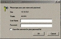
-
Provide your user name and password.
If you have not modified the default login authentication on the switch, use your enable mode password and leave the User Name field blank.
For more information on how to configure authentication, refer to the Configuring Authentication Login section of Catalyst 6500 Series, 4500 Series, and 5000 Family Switches Web Interface Installation and Configuration Note.
The home page of the switch appears in your browser.
-
Click Switch Manager in order to download the CiscoView client software.
After a few minutes, you see a dialog box that grants the current Java session.
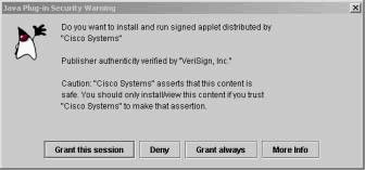
-
Click Grant this session or Grant always in order to continue.
If the JPI freezes at this point, a JPI update to version 1.3.1 can be necessary. Refer to Sun Microsystems Java 2 Platform, Enterprise Edition (J2EE) 1.3
 in order to download the plug-in.
 The CiscoView authentication dialog box displays.
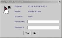
-
Enter your enable password without a user name, if you use the default authentication, or enter your configured authentication information.
The community string dialog box displays.
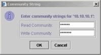
-
Click OK in order to accept the default string that is provided, or enter new values in the Read Community and Write Community fields and click OK.
Only change the strings that are provided if you have modified these string names.
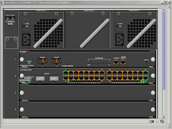
This action completes the download and login of the CiscoView image. A visual representation of the switch displays.
-
Click on specific components in order to view the current configuration or to configure the components.
Summary
The CiscoView interface is a subset of the total features that are available in CiscoView 5.x. You cannot monitor CPU or memory usage with CiscoView. However, CiscoView does provide a view of which ports are up and running and which are not. CiscoView also provides many basic port and VLAN management tasks.
The primary purpose of CiscoView is to provide a GUI to configure the switch for the customers who do not want to purchase the CiscoView 5.x network management system. For more information on how to configure a Catalyst switch with CiscoView, refer to the Configuring Your Devices section of Using CiscoView 5.3.
Related Information
Contact Cisco
- Open a Support Case

- (Requires a Cisco Service Contract)


 Feedback