QoS Output Scheduling on Catalyst 6500/6000 Series Switches Running CatOS System Software
Available Languages
Contents
Introduction
Output scheduling ensures that important traffic is not dropped in the event of heavy oversubscription. This document discusses all the techniques and algorithms that are involved in output scheduling on Cisco Catalyst 6500/6000 series switches that run Catalyst OS (CatOS) system software. This document also provides a brief overview of the queuing capability of Catalyst 6500/6000 switches and how to configure the different parameters of output scheduling.
Note: If you run Cisco IOS® Software on your Catalyst 6500/6000, refer to QoS Output Scheduling on Catalyst 6500/6000 Series Switches Running Cisco IOS System Software for more information.
Prerequisites
Requirements
There are no specific requirements for this document.
Components Used
The examples in this document were created from a Catalyst 6000 with a Supervisor Engine 1A and a Policy Feature Card (PFC). But the examples are also valid for a Supervisor Engine 2 with a PFC2 or for a Supervisor Engine 720 with a PFC3.
The information in this document was created from the devices in a specific lab environment. All of the devices used in this document started with a cleared (default) configuration. If your network is live, make sure that you understand the potential impact of any command.
Conventions
Refer to Cisco Technical Tips Conventions for more information on document conventions.
Background Information
Output Queue Drops
Output drops are caused by a congested interface. A common cause of this might be traffic from a high bandwidth link that is being switched to a lower bandwidth link or traffic from multiple inbound links that are being switched to a single outbound link.
For example, if a large amount of bursty traffic comes in on a gigabit interface and is switched out to a 100 Mbps interface, this might cause output drops to increment on the 100 Mbps interface. This is because the output queue on that interface is overwhelmed by the excess traffic due to the speed mismatch between the incoming and outgoing bandwidths. The traffic rate on the outgoing interface cannot accept all packets that should be sent out.
The ultimate solution to resolve the problem is to increase the line speed. However, there are ways to prevent, decrease, or control output drops when you do not want to increase the line speed. You can prevent output drops only if output drops are a consequence of short bursts of data. If output drops are caused by a constant high-rate flow, you cannot prevent the drops. However, you can control them.
Types of Queuing That Are Involved in Output Scheduling on the Catalyst 6500/6000
Tail Drop
Tail drop is a basic congestion avoidance mechanism. Tail drop treats all traffic equally and does not differentiate between classes of service (CoSs) when queues begin to fill during periods of congestion. When the output queue is full and tail drop is in effect, packets are dropped until the congestion is eliminated and the queue is no longer full. Tail drop is the most basic type of congestion avoidance and does not take into account any QoS parameter.
The Catalyst 6000 has implemented an advanced version of tail drop congestion avoidance that drops all packets with a certain CoS when a certain percentage of buffer filling is reached. With weighted tail drop, you can define a set of thresholds and associate a CoS with each threshold. In the example in this section, there are four possible thresholds. The definitions of each threshold are:
-
Threshold 1 is reached when 50 percent of the buffer is filled. CoS 0 and 1 are assigned to this threshold.
-
Threshold 2 is reached when 60 percent of the buffer is filled. CoS 2 and 3 are assigned to this threshold.
-
Threshold 3 is reached when 80 percent of the buffer is filled. CoS 4 and 5 are assigned to this threshold.
-
Threshold 4 is reached when 100 percent of the buffer is filled. CoS 6 and 7 are assigned to this threshold.
In the diagram in Figure 1, all packets with a CoS of 0 or 1 are dropped if the buffer is 50 percent filled. All packets with a CoS of 0, 1, 2, or 3 are dropped if the buffers are 60 percent filled. Packets with a CoS of 6 or 7 are dropped when the buffers are completely filled.
Figure 1 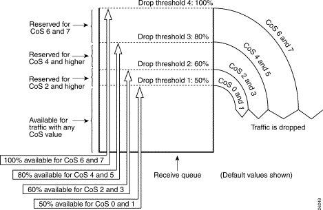
Note: As soon as the buffer filling drops below a certain threshold, packets with the associated CoS are no longer dropped.
Random Early Detection and Weighted Random Early Detection
Weighted random early detection (WRED) is a congestion avoidance mechanism which randomly drops packets with a certain IP precedence when the buffers reach a defined filling threshold. WRED is a combination of these two features:
-
Tail drop
-
Random early detection (RED)
RED is not precedence-aware or CoS-aware. RED uses one of the single thresholds when the threshold value for the buffer fills. RED starts to randomly drop packets (but not all packets, as in tail drop) until the maximum (max) threshold is reached. After the max threshold is reached, all packets are dropped. The probability that a packet is dropped increases linearly with the increase of buffer filling above the threshold. The diagram in Figure 2 shows the packet drop probability:
Figure 2 – Packet Discard Probability 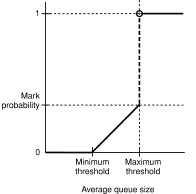
Note: The mark probability in this diagram is tunable in RED, which means that the slope of the linear drop probability is adjustable.
RED and WRED are very useful congestion avoidance mechanisms for TCP-based traffic. For other types of traffic, RED is not very efficient. This is because RED takes advantage of the windowing mechanism that TCP uses to manage congestion. RED avoids the typical congestion that occurs on a router when multiple TCP sessions go through the same router port. The mechanism is called global network synchronization. The diagram in Figure 3 shows how RED has a smoothing effect on the load:
Figure 3 – RED for Congestion Avoidance 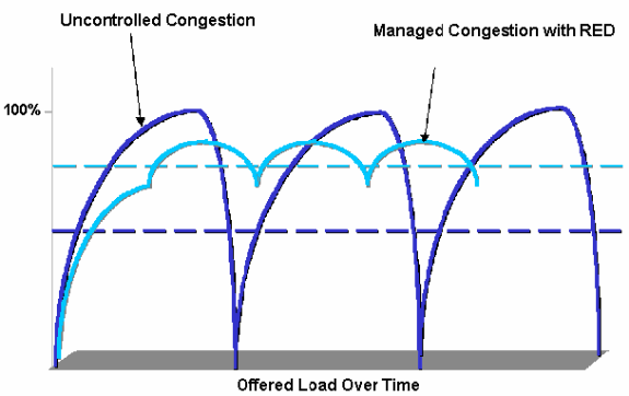
For more information on how RED can reduce congestion and smooth the traffic through the router, refer to the How the Router Interacts with TCP section of the document Congestion Avoidance Overview.
WRED is similar to RED in that both define some minimum (min) thresholds and, when those min thresholds are reached, packets are randomly dropped. WRED also defines certain max thresholds and, when those max thresholds are reached, all packets are dropped. WRED is also CoS-aware, which means that one or more CoS values are added to each min threshold/max threshold pair. When the min-threshold is exceeded, packets are randomly dropped with the CoS that is assigned. Consider this example with two thresholds in the queue:
-
CoS 0 and 1 are assigned to min threshold 1 and to max threshold 1. Min threshold 1 is set to 50 percent of buffer filling, and max threshold 1 is set to 80 percent.
-
CoS 2 and 3 are assigned to min threshold 2 and to max threshold 2. Min threshold 2 is set to 70 percent of buffer filling, and max threshold 2 is set to 100 percent.
As soon as the buffer exceeds min threshold 1 (50 percent), packets with CoS 0 and 1 start to be randomly dropped. More packets are dropped as the buffer utilization grows. If min threshold 2 (70 percent) is reached, packets with CoS 2 and 3 begin to be randomly dropped.
Note: At this stage, the drop probability for packets with CoS 0 and 1 is much higher than the drop probability for packets with CoS 2 or CoS 3.
Whenever max threshold 2 is reached, packets with CoS 0 and 1 are all dropped, while packets with CoS 2 and 3 continue to be randomly dropped. Finally, when 100 percent is reached (max threshold 2), all packets with CoS 2 and 3 are dropped.
The diagrams in Figure 4 and Figure 5 illustrate an example of these thresholds:
Figure 4 – WRED with Two Sets of Min Thresholds and Max Thresholds (Two Services) 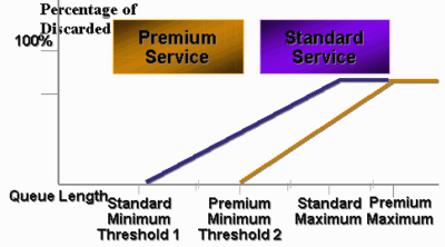
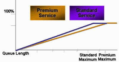
The early CatOS implementation of WRED only set the max threshold, while the min threshold was hard coded to 0 percent. The bottom part of the diagram in Figure 5 highlights the resulting behavior.
Note: The drop probability for a packet is always non-null because this probability is always above the min threshold. This behavior has been corrected in software version 6.2 and later.
Weighted Round-Robin
Weighted round-robin (WRR) is another mechanism for output scheduling on the Catalyst 6000. WRR works between two or more queues. The queues for WRR are emptied in a round-robin fashion, and you can configure the weight for each queue. By default, ports have two WRR queues on the Catalyst 6000. The default is:
-
To serve the high-priority WRR queue 70 percent of time
-
To serve the low-priority WRR queue 30 percent of time
The diagram in Figure 6 shows a WRR that has three queues that are served in a WRR fashion. The high-priority queue (red packets) sends more packets than the two other queues:
Figure 6 – Output Scheduling: WRR 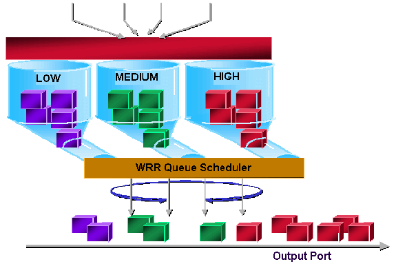
Note: Most of the 6500 line cards do implement WRR per bandwidth. This implementation of WRR per bandwidth means that every time the scheduler allows a queue to transmit packets, a certain number of bytes are allowed to be transmitted. This number of bytes can represent more than one packet. For example, if you send 5120 bytes in one turn, you can send three 1518-byte packets, for a total of 4554 bytes. The bytes in excess are lost (5120 – 4554 = 566 bytes). Therefore, with some extreme weight (like 1 percent for queue 1 and 99 percent for queue 2), the exact configured weight may not be reached. This failure to reach to exact weight is often the case for larger packets.
Some new-generation line cards, like the 6548-RJ-45, overcome this limitation through the implementation of deficit weighted round-robin (DWRR). DWRR transmits from the queues but does not starve the low-priority queue. DWRR keeps track of the low-priority queue that is under transmission and compensates in the next round.
Strict Priority Queue
Another type of queue in the Catalyst 6000, a strict priority queue, is always emptied first. As soon as there is a packet in the strict priority queue, the packet is sent.
The WRR or WRED queues are checked only after the strict priority queue is emptied. After each packet is transmitted from either the WRR queue or the WRED queue, the strict priority queue is checked and emptied, if necessary.
Note: All line cards with a queuing type similar to 1p2q1t, 1p3q8t, and 1p7q8t use DWRR. Other line cards use standard WRR.
Output Queuing Capability of Different Line Cards on the Catalyst 6000
show port Command Capabilities
If you are not sure about the queuing capability of a port, you can issue the show port capabilities command. This is the output from the command on a WS-X6408-GBIC line card:
Model                  WS-X6408-GBIC
Port                   4/1
Type                   No GBIC
Speed                  1000
Duplex                 full
Trunk encap type       802.1Q,ISL
Trunk mode             on,off,desirable,auto,nonegotiate
Channe                 yes
Broadcast suppression  percentage(0-100)
Flow control           receive-(off,on,desired),send-(off,on,desired)
Security               yes
MembershIP             static,dynamic
Fast start             yes
QOS scheduling         rx-(1q4t),tx-(2q2t)
CoS rewrite            yes
ToS rewrite            DSCP
UDLD                   yes
SPAN                   source,destination
COPS port group        none
This port has a type of queuing output that is called 2q2t.
Understand the Queuing Capability of a Port
There are several types of queues that are available on Catalyst 6500/6000 switches. The tables in this section may become incomplete as new line cards are released. New line cards can introduce new queuing combinations. For a current description of all queuing that is available for Catalyst 6500/6000 switch modules, refer to the Configuring QoS section for your CatOS version of Catalyst 6500 Series Software Documentation.
Note: Cisco Communication Media Module (CMM) does not support all QoS features. Check the release notes for your specific software release in order to determine the features that are supported.
This table explains the notation of the port QoS architecture:
| Tx1/Rx2 ide | Queue Notation | No. of Queues | Priority Queue | No. of WRR Queues | No. and Type of Threshold for WRR Queues |
|---|---|---|---|---|---|
| Tx | 2q2t | 2 | — | 2 | 2 configurable tail drop |
| Tx | 1p2q2t | 3 | 1 | 2 | 2 configurable WRED |
| Tx | 1p3q1t | 4 | 1 | 3 | 1 configurable WRED |
| Tx | 1p2q1t | 3 | 1 | 2 | 1 configurable WRED |
| Rx | 1q4t | 1 | — | 1 | 4 configurable tail drop |
| Rx | 1p1q4t | 2 | 1 | 1 | 4 configurable tail drop |
| Rx | 1p1q0t | 2 | 1 | 1 | Not configurable |
| Rx | 1p1q8t | 2 | 1 | 1 | 8 configurable WRED |
1 Tx = transmit.
2 Rx = receive.
This table lists all the modules and the queue types in the Rx and Tx side of the interface or port:
| Module | Rx Queues | Tx Queues |
|---|---|---|
| WS-X6K-S2-PFC2 | 1p1q4t | 1p2q2t |
| WS-X6K-SUP1A-2GE | 1p1q4t | 1p2q2t |
| WS-X6K-SUP1-2GE | 1q4t | 2q2t |
| WS-X6501-10GEX4 | 1p1q8t | 1p2q1t |
| WS-X6502-10GE | 1p1q8t | 1p2q1t |
| WS-X6516-GBIC | 1p1q4t | 1p2q2t |
| WS-X6516-GE-TX | 1p1q4t | 1p2q2t |
| WS-X6416-GBIC | 1p1q4t | 1p2q2t |
| WS-X6416-GE-MT | 1p1q4t | 1p2q2t |
| WS-X6316-GE-TX | 1p1q4t | 1p2q2t |
| WS-X6408A-GBIC | 1p1q4t | 1p2q2t |
| WS-X6408-GBIC | 1q4t | 2q2t |
| WS-X6524-100FX-MM | 1p1q0t | 1p3q1t |
| WS-X6324-100FX-SM | 1q4t | 2q2t |
| WS-X6324-100FX-MM | 1q4t | 2q2t |
| WS-X6224-100FX-MT | 1q4t | 2q2t |
| WS-X6548-RJ-21 | 1p1q0t | 1p3q1t |
| WS-X6548-RJ-45 | 1p1q0t | 1p3q1t |
| WS-X6348-RJ-21 | 1q4t | 2q2t |
| WS-X6348-RJ21V | 1q4t | 2q2t |
| WS-X6348-RJ-45 | 1q4t | 2q2t |
| WS-X6348-RJ-45V | 1q4t | 2q2t |
| WS-X6148-RJ-45V | 1q4t | 2q2t |
| WS-X6148-RJ21V | 1q4t | 2q2t |
| WS-X6248-RJ-45 | 1q4t | 2q2t |
| WS-X6248A-TEL | 1q4t | 2q2t |
| WS-X6248-TEL | 1q4t | 2q2t |
| WS-X6024-10FL-MT | 1q4t | 2q2t |
Create QoS on the Catalyst 6500/6000
Three fields on the Catalyst 6500/6000 are used to make QoS:
-
The IP precedence—The first three bits of the Type of Service (ToS) field in the IP header
-
The differentiated services code point (DSCP)—The first six bits of the ToS field in the IP header
-
The CoS—The three bits used at the Layer 2 (L2) level
These three bits are either part of the Inter-Switch Link (ISL) header or are inside the IEEE 802.1Q (dot1q) tag. There is no CoS inside an untagged Ethernet packet.
Output Scheduling Mechanism on the Catalyst 6500/6000
When a frame is sent from the data bus to be transmitted, the CoS of the packet is the only parameter that is considered. The packet then goes through a scheduler, which chooses the queue into which the packet is put. Therefore, remember that output scheduling and all mechanisms that this document discusses are only CoS-aware.
The Catalyst 6500/6000 with a Multilayer Switch Feature Card (MSFC) uses an internal DSCP in order to classify the packet. The Catalyst 6500/6000 that is configured with QoS enabled assigns a DSCP value when the forwarding decision is made at the PFC level. This DSCP is assigned to any packet, which includes non-IP packets, and is mapped to the CoS in order to enable output scheduling. You can configure the mapping from DSCP to CoS values on the Catalyst 6500/6000. If you leave the default value, you can derive the CoS from the DSCP. The formula is:
DSCP_value / 8
In addition, the DSCP value is mapped into the CoS of the outgoing packet, if the packet is an IP packet that is ISL or dot1q (non-native VLAN) tagged. The DSCP value is also written inside the ToS field of the IP header.
The diagram in Figure 7 shows a 1p2q2t queue. The WRR queues are emptied with the use of the WRR scheduler. There is also an arbiter that checks between each packet from the WRR queues in order to determine if there is something in the strict priority queue.
Figure 7 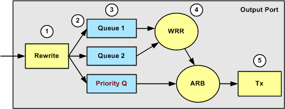
-
The ToS field is rewritten in the IP header and the 802.1p/ISL CoS field.
-
The scheduling queue and threshold are selected on the basis of the CoS, through a configurable map.
-
Each queue has configurable size and thresholds, and some queues have WRED.
-
Dequeuing uses WRR between two queues.
-
Outgoing encapsulation can be dot1q, ISL, or none.
Configuration, Monitoring, and Output Scheduling on the Catalyst 6500/6000
Default Configuration for QoS on the Catalyst 6500/6000
This section provides sample output from the default QoS configuration on a Catalyst 6500/6000, in addition to information on what these values mean and how you can tune the values.
QoS is disabled by default when you issue this command:
set qos disable
The commands in this list show the default assignment for each CoS in a 2q2t port. Queue 1 has CoS 0 and 1 assigned to its first threshold and has CoS 2 and 3 assigned to its second threshold. Queue 2 has CoS 4 and 5 assigned to its first threshold and has CoS 6 and 7 assigned to its second threshold:
set qos map 2q2t tx 1 1 cos 0

set qos map 2q2t tx 1 1 cos 1

set qos map 2q2t tx 1 2 cos 2

set qos map 2q2t tx 1 2 cos 3

set qos map 2q2t tx 2 1 cos 4

set qos map 2q2t tx 2 1 cos 5

set qos map 2q2t tx 2 2 cos 6

set qos map 2q2t tx 2 2 cos 7
These commands display the threshold level by default on a 2q2t port for each queue:
set qos drop-threshold 2q2t tx queue 1 80 100

set qos drop-threshold 2q2t tx queue 2 80 100
You can assign the default weight to each of the WRR queues. Issue this command in order to assign the default weights for queue 1 and queue 2:
Note: The low-priority queue is served 5/260 percent of the time, and the high-priority queue is served 255/260 percent of the time.
set qos wrr 2q2t 5 255
The total buffer availability is split among the two queues. The low-priority queue is correctly assigned to 80 percent of the buffers that are available because this is the queue that is most likely to have packets buffered and sitting for some time. Issue this command in order to define the availability:
set qos txq-ratio 2q2t 80 20
You can view similar settings for the 1p2q2t port in this configuration:
set qos map 1p2q2t tx 1 1 cos 0

set qos map 1p2q2t tx 1 1 cos 1

set qos map 1p2q2t tx 1 2 cos 2

set qos map 1p2q2t tx 1 2 cos 3

set qos map 1p2q2t tx 2 1 cos 4

set qos map 1p2q2t tx 3 1 cos 5

set qos map 1p2q2t tx 2 1 cos 6

set qos map 1p2q2t tx 2 2 cos 7

set qos wrr 1p2q2t 5 255

set qos txq-ratio 1p2q2t 70 15 15

set qos wred 1p2q2t tx queue 1 80 100

set qos wred 1p2q2t tx queue 2 80 100
Note: By default, CoS 5 (voice traffic) is assigned to the strict priority queue.
Configuration
The first configuration step is to enable QoS. Remember that QoS is disabled by default. When QoS is disabled, the CoS mapping is irrelevant. There is a single queue that is served as FIFO, and all packets get dropped there.
bratan> (enable) set qos enable

QoS is enabled

bratan> (enable) show qos status

QoS is enabled on this switch
The CoS value needs to be assigned to the queue or threshold for all queue types. The mapping that is defined for a 2q2t type of port is not applied to any 1p2q2t port. Also, the mapping that is made for 2q2t is applied to all ports that have a 2q2t queuing mechanism. Issue this command:
set qos map queue_type tx Q_number threshold_number cos value
Note: Queues are always numbered to start with the lowest possible priority queue and end with the strict priority queue that is available. Here is an example:
-
Queue 1 is the low-priority WRR queue
-
Queue 2 is the high-priority WRR queue
-
Queue 3 is the strict priority queue
You must repeat this operation for all types of queues. Otherwise, you keep the default CoS assignment. Here is an example for 1p2q2t:
Configuration
set qos map 1p2q2t tx 1 1 cos 0

!--- This is the low-priority WRR queue threshold 1, CoS 0 and 1.

set qos map 1p2q2t tx 1 1 cos 1 and 1

set qos map 1p2q2t tx 1 2 cos 2

!--- This is the low-priority WRR queue threshold 2, CoS 2 and 3.

set qos map 1p2q2t tx 1 2 cos 3 and 3

set qos map 1p2q2t tx 2 1 cos 4

!--- This is the high-priority WRR queue threshold 1, CoS 4.

set qos map 1p2q2t tx 3 1 cos 5

!--- This is the strict priority queue, CoS 5.

set qos map 1p2q2t tx 2 1 cos 6

!--- This is the high-priority WRR queue threshold 2, CoS 6.

set qos map 1p2q2t tx 2 2 cos 7 and 7
Console Output
tamer (enable) set qos map 1p2q2t tx 1 1 cos 0

QoS tx priority queue and threshold mapped to cos successfully
You must configure the WRR weight for the two WRR queues. Issue this command:
set qos wrr Q_type weight_1 weight_2
Weight_1 relates to queue 1, which should be the low-priority WRR queue. Weight_1 must always be lower than weight_2. The weight can take any value between 1 and 255. You can assign the percentage with these formulas:
-
Queue 1:
weight_1 / (weight_1 + weight_2)
-
Queue 2:
weight_2 / (weight_1 + weight_2)
You must also define the weight for the various types of queues. The weight does not need to be the same. For example, for 2q2t, where queue 1 is served 30 percent of the time and queue 2 is served 70 percent of the time, you can issue this command in order to define the weight:
set qos wrr 2q2t 30 70

!--- This ensures that the high-priority WRR queue is served 70 percent of the time !--- and that the low-priority WRR queue is served 30 percent of the time.
Console Output
tamer (enable) set qos wrr 2q2t 30 70

QoS wrr ratio is set successfully
You also must define the transmit queue ratio, which refers to the way that the buffers are split among the different queues. Issue this command:
set qos txq-ratio port_type queuel_val queue2_val ... queueN_val
Note: If you have three queues (1p2q2t), you must set the high-priority WRR queue and the strict priority queue at the same level for hardware reasons.
Configuration
set qos txq-ratio 1p2q2t 70 15 15

!--- This gives 70 percent of the buffer of all 1p2q2t ports to the low-priority WRR !--- queue and gives 15 percent to each of the other two queues.

set qos txq-ratio 2q2t 80 20

!--- This gives 80 percent of the buffer to the low-priority queue, !--- and gives 20 percent of the buffer to the high-priority queue.
Console Output
tamer (enable) set qos txq-ratio 1p2q2t 70 15 20

Queue ratio values must be in range of 1-99 and add up to 100
Example: set qos txq-ratio 2q2t 20 80

tamer (enable) set qos txq-ratio 1p2q2t 70 30 30

Queue ratio values must be in range of 1-99 and add up to 100
Example: set qos txq-ratio 2q2t 20 80

tamer (enable) set qos txq-ratio 1p2q2t 80 10 10

QoS txq-ratio is set successfully
As this console output illustrates, the sum of the queue values must be 100. Leave the largest part of the buffers for the low-priority WRR queue because this queue needs the most buffering. The other queues are served with higher priority.
The last step is to configure the threshold level for the WRED queue or for the tail drop queue. Issue these commands:
set qos wred port_type [tx] queue q_num thr1 thr2 ... thrn


set qos drop-threshold port_type tx queue q_num thr1 ... thr2
Configuration
set qos drop-threshold 2q2t tx queue 1 50 80

!--- For low-priority queues in the 2q2t port, the first threshold is defined at 50 !--- percent and the second threshold is defined at 80 percent of buffer filling.

set qos drop-threshold 2q2t tx queue 2 40 80

!--- For high-priority queues in the 2q2t port, the first threshold is defined at 40 !--- percent and the second threshold is defined at 80 percent of buffer filling.

set qos wred 1p2q2t tx queue 1 50 90

!--- The commands for the 1p2q2t port are identical.

set qos wred 1p2q2t tx queue 2 40 80
Console Output
tamer (enable) set qos drop-threshold 2q2t tx queue 1 50 80

Transmit drop thresholds for queue 1 set at 50% 80%

tamer (enable) set qos drop-threshold 2q2t tx queue 2 40 80

Transmit drop thresholds for queue 2 set at 40% 80%

tamer (enable) set qos wred 1p2q2t tx queue 1 50 90

WRED thresholds for queue 1 set to 50 and 90 on all WRED-capable 1p2q2t ports

tamer (enable) set qos wred 1p2q2t tx queue 2 40 80

WRED thresholds for queue 2 set to 40 and 80 on all WRED-capable 1p2q2t ports
The set qos wred 1p2q2t tx queue 2 40 80 command works in conjunction with the CoS for threshold mapping. For example, when you issue the commands in the list below, you ensure that—on the 1p2q2t port in the transmit direction—packets with CoS 0,1, 2, and 3 are sent in the first queue (the low WRR queue). When the buffers in that queue are 50 percent filled, WRED begins to drop packets with CoS 0 and 1. Packets with CoS 2 and 3 are dropped only when the buffers on the queue are 90 percent filled.
set qos map 1p2q2t tx 1 1 cos 0

set qos map 1p2q2t tx 1 1 cos 1

set qos map 1p2q2t tx 1 2 cos 2

set qos map 1p2q2t tx 1 2 cos 3

set qos wred 1p2q2t tx queue 1 50 90
Monitor Output Scheduling and Verify the Configuration
A simple command to use in order to verify the current runtime configuration for the output scheduling of a port is show qos info runtime mod/port . The command displays this information:
-
The type of queuing on the port
-
The mapping of CoS to the different queues and thresholds
-
The buffer sharing
-
The WRR weight
In this example, the values are at 20 percent WRR for queue 1 and 80 percent WRR for queue 2:
tamer (enable) show qos info runtime 1/1

Run time setting of QoS:
QoS is enabled
Policy Source of port 1/1: Local
Tx port type of port 1/1 : 1p2q2t
Rx port type of port 1/1 : 1p1q4t
Interface type: port-based
ACL attached:
The qos trust type is set to untrusted
Default CoS = 0
Queue and Threshold Mapping for 1p2q2t (tx):
Queue   Threshold     CoS
-----   ---------    -------
1          1           0 1
1          2           2 3
2          1           4 6
2          2           7
3          1           5
Queue and Threshold Mapping for 1p1q4t (rx):
All packets are mapped to a single queue
Rx drop thresholds:
Rx drop thresholds are disabled
Tx drop thresholds:
Tx drop-thresholds feature is not supported for this port type
Tx WRED thresholds:
Queue #        Thresholds - percentage (* abs values)
-------     ------------------------------------------
1             80% (249088 bytes) 100% (311168 bytes)
2             80% (52480 bytes) 100% (61440 bytes)
Queue Sizes:
Queue #       Sizes - percentage (* abs values)
-------       -------------------------------------
1                70% (311296 bytes)
2                15% (65536 bytes)
3                15% (65536 bytes)
WRR Configuration of ports with speed 1000Mbps:
Queue #       Ratios (* abs values)
-------       -------------------------------------
1                20 (5120 bytes)
2                80 (20480 bytes)
(*) Runtime information may differ from user configured setting
due to hardware granularity.
tamer (enable)
In the next example, note that the WRR weights are not the default value of 1. The weights have been set to the values of 20 for queue 1 and 80 for queue 2. This example uses a traffic generator to send 2 Gb of traffic to a Catalyst 6000. These 2 Gb of traffic should exit through port 1/1. Because port 1/1 is oversubscribed, many packets are dropped (1 Gbps). The show mac command shows that there is a lot of output drop:
tamer (enable) show mac 1/1

Port            Rcv-Unicast            Rcv-Multicast           Rcv-Broadcast
--------     --------------------   --------------------   --------------------
1/1                  0                     1239                     0

Port             Xmit-Unicast             Xmit-Multicast        Xmit-Broadcast
--------     --------------------     --------------------  --------------------
1/1             73193601                     421                     0

Port            Rcv-Octet                 Xmit-Octet
--------     --------------------    --------------------
1/1              761993                  100650803690

MAC          Dely-Exced         MTU-Exced         In-Discard         Out-Discard
--------    --------------   ----------------   ---------------   -----------------
1/1              0                 -                  0              120065264

Last-Time-Cleared
--------------------------
Fri Jan 12 2001, 17:37:43
Consider the packets that are dropped. This is how the pattern of traffic suggested is split:
-
1 Gb of traffic with IP precedence 0
-
250 Mb of traffic with IP precedence 4
-
250 Mb of traffic with IP precedence 5
-
250 Mb of traffic with IP precedence 6
-
250 Mb of traffic with IP precedence 7
According to CoS mapping, this traffic is sent:
-
1 Gb of traffic to queue 1 threshold 1
-
0 Mb of traffic to queue 1 threshold 2
-
500 Mb of traffic to queue 2 threshold 1
-
250 Mb of traffic to queue 2 threshold 2
-
250 Mb of traffic to queue 3 (strict priority queue)
The switch must trust the received traffic so that the incoming IP precedence is preserved in the switch and is used to map to the CoS value for output scheduling.
Note: The default IP precedence to CoS mapping is IP precedence equals CoS.
Issue the show qos stat 1/1 command in order to see the packets that were dropped and the approximate percentage:
-
At this point, no packets are dropped in queue 3 (CoS 5).
-
91.85 percent of the packets dropped are CoS 0 packets in queue 1.
-
8 percent of the dropped packets are CoS 4 and 6 in queue 2, threshold 1.
-
0.15 percent of the dropped packets are CoS 7 in queue 2, threshold 2.
This output illustrates use of the command:
tamer (enable) show qos stat 1/1

Tx port type of port 1/1 : 1p2q2t
Q3T1 statistics are covered by Q2T2.
Q #       Threshold #:Packets dropped
---      -------------------------------
1         1:110249298 pkts, 2:0 pkts
2         1:9752805 pkts, 2:297134 pkts
3         1:0 pkts
Rx port type of port 1/1 : 1p1q4t
Rx drop threshold counters are disabled for untrusted ports
Q #       Threshold #:Packets dropped
---     ---------------------------------
1         1:0 pkts, 2:0 pkts, 3:0 pkts, 4:0 pkts
2         1:0 pkts
If you change the WRR weight back to the default value after the counters have been cleared, only 1 percent of the dropped packets occur in queue 2 instead of the 8 percent that appeared previously:
Note: The default value is 5 for queue 1 and 255 for queue 2.
tamer (enable) show qos stat 1/1

TX port type of port 1/1 : 1p2q2t
Q3T1 statistics are covered by Q2T2
Q #               Threshold #:Packets dropped
---             ----------------------------------
1                 1:2733942 pkts, 2:0 pkts
2                 1:28890 pkts, 2:6503 pkts
3                 1:0 pkts
Rx port type of port 1/1 : 1p1q4t
Rx drop threshold counters are disabled for untrusted ports
Q #               Threshold #:Packets dropped
---             ------------------------------------
1                  1:0 pkts, 2:0 pkts, 3:0 pkts, 4:0 pkts
2                  1:0 pkts
Use Output Scheduling to Reduce Delay and Jitter
The example in the section Monitor Output Scheduling and Verify the Configuration demonstrates the benefit of output scheduling implementation, which avoids a drop of VoIP or mission-critical traffic in the event of oversubscription of the output port. Oversubscription occurs infrequently in a normal network, particularly on a Gigabit link. Usually, oversubscription only happens during peak traffic times or during bursts of traffic within a very short period of time.
Even without any oversubscription, output scheduling can be of great help in a network where QoS is implemented end-to-end. Output scheduling helps to reduce delay and jitter. This section provides examples of how output scheduling can help reduce delay and jitter.
Reduce Delay
The delay of a packet is increased by the time “lost” in the buffer of each switch during the wait for transmission. For example, a small voice packet with a CoS of 5 is sent out of a port during a large backup or file transfer. If you do not have any QoS for the output port, and if you assume that the small voice packet is queued after 10 large 1500-byte packets, you can easily calculate the Gigabit speed time that is necessary to transmit the 10 large packets:
(10 × 1500 × 8) = 120,000 bits that are transmitted in 120 microseconds
If this packet needs to cross eight or nine switches while it passes through the network, a delay of about 1 ms can result. This amount counts only delays in the output queue of the switch that is crossed in the network.
Note: If you need to queue the same 10 large packets on a 10-Mbps interface (for example, with an IP phone and with a PC connected), the delay that is introduced is:
(10 × 1500 × 8) = 120,000 bits that are transmitted in 12 ms
Output scheduling implementation ensures that voice packets with a CoS of 5 are put in the strict priority queue. This placements ensures that these packets are sent before any packets with a CoS of less than 5, which reduces the delays.
Reduce Jitter
Another important benefit of output scheduling implementation is that it reduces jitter. Jitter is the variation in delay that is observed for packets within the same flow. The diagram in Figure 8 shows an example scenario of how output scheduling can reduce jitter:
Figure 8 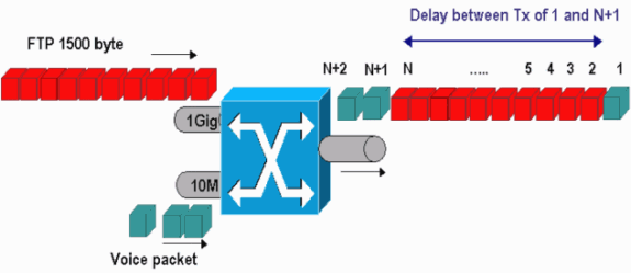
In this scenario, there are two streams that a single output port must send:
-
One voice stream that is incoming on a 10-Mbps Ethernet port
-
One FTP stream that is incoming on a 1-Gbps Ethernet uplink
Both streams leave the switch through the same output port. This example shows what can happen without the use of output scheduling. All large data packets can be interleaved between two voice packets, which creates jitter in the reception of the voice packet from the same stream. There is a larger delay between the reception of packet n and packet n+1 as the switch transmits the large data packet. However, the delay between n+1 and n+2 is negligible. This results in jitter in the voice traffic stream. You can easily avoid this problem with the use of a strict priority queue. Ensure that the CoS value of the voice packets is mapped to the strict priority queue.
Related Information
Revision History
| Revision | Publish Date | Comments |
|---|---|---|
1.0 |
13-Apr-2007 |
Initial Release |
Contact Cisco
- Open a Support Case

- (Requires a Cisco Service Contract)
 Feedback