Catalyst 6500 Series Switches Using VPLS Configuration Example
Available Languages
Contents
Introduction
This document provides a sample configuration for Virtual Private LAN Service (VPLS) on the Cisco Catalyst 6500 Series Switches in order to enables enterprises to link together their Ethernet-based LANs from multiple sites through by their service provider.
Prerequisites
Requirements
Ensure that you meet these requirements before you attempt this configuration:
-
Basic knowledge of configuration on Cisco Catalyst 6500 Series Switches
-
Have basic knowledge of VPLS
Components Used
The information in this document is based on the Cisco Catalyst 6500 Series Switch.
VPLS is supported on Catalyst 6500 Switch with SIP-600/SUP3B or later with Cisco IOS® Software Release 12.2(33)SXH or later. Switch requires the use of SIP cards to perform the VPLS functionality.
The information in this document was created from the devices in a specific lab environment. All of the devices used in this document started with a cleared (default) configuration. If your network is live, make sure that you understand the potential impact of any command.
Conventions
Refer to the Cisco Technical Tips Conventions for more information on document conventions.
Background Information
From the enterprise perspective, VPLS uses the public network of the service provider as one giant Ethernet LAN that connects multiple sites CE devices, which appears to connect to a logical bridge that is managed over a IP/MPLS network.
VPLS simplifies the LAN/WAN boundary and presents as an ethernet interface, which appears to be on the same LAN, regardless of location.
First create a virtual forwarding instance (VFI) on each Catalyst 6500 switch in order to set up a VPLS. The VFI specifies the VPN ID of a VPLS domain, the addresses of other device in the domain, and the type of tunnel signaling and encapsulation mechanism for each peer device. The set of VFIs formed by the interconnection of the devices is called a VPLS instance, which forms the logic bridge over a packet switched network.
The packet forwarding decision is made when you look for the Layer 2 virtual forwarding instance (VFI). In order to avoid the problem of a packet looping in the provider core, devices enforce a split-horizon principle for the emulated VCs.
Before you configure VPLS, configure MPLS in the core so that a label switched path (LSP) exists between the devices.
Configure
In this section, you are presented with the information to configure the features described in this document.
Note: Use the Command Lookup Tool (registered customers only) to obtain more information on the commands used in this section.
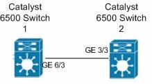
Network Diagram
This document uses this network setup:

Configurations
This document uses these configurations:
| Catalyst 6500 Switch 1 |
|---|
switch6500_1#configure terminal !--- Enable the Layer 2 VFI manual configuration mode. switch6500_1(config)#l2 vfi VPLS-A manual !--- Configure a VPN ID for a VPLS domain. switch6500_1(config-vfi)#vpn id 500 !--- Specify the remote peering router ID !--- and the tunnel encapsulation type or the pseudo-wire !--- property to be used to set up the emulated VC. switch6500_1(config-vfi)#neighbor 10.7.1.3 encapsulation mpls switch6500_1(config-vfi)#exit switch6500_1(config)#interface Loopback 0 switch6500_1(config-if)#ip address 10.7.1.2 255.255.255.255 switch6500_1(config)#interface GigabitEthernet 6/3 switch6500_1(config-if)#switchport !--- Set the interface as an 802.1Q tunnel port. switch6500_1(config-if)#switchport mode dot1qtunnel !--- Set the VLAN when the interface is in Access mode. switch6500_1(config-if)#switchport access vlan 500 !--- Create a dynamic switched virtual interface (SVI). switch6500_1(config)#interface Vlan 500 !--- Disable IP processing. switch6500_1(config-if)#no ip address !--- Specify the Layer 2 VFI that you are binding to the VLAN port. switch6500_1(config-if)#xconnect vfi VPLS-A switch6500_1(config-if)#exit switch6500_1(config)#interface vlan 500 switch6500_1(config-vlan)#state active switch6500_1(config-vlan)#exit !--- Save the configurations in the device. switch6500_1(config)#copy running-config startup-config switch6500_1(config)#exit |
| Catalyst 6500 Switch 2 |
|---|
switch6500_2#configure terminal switch6500_2(config)#l2 vfi VPLS-B manual switch6500_2(config-vfi)#vpn id 500 switch6500_2(config-vfi)#neighbor 10.7.1.2 encapsulation mpls switch6500_2(config-vfi)#exit switch6500_2(config)#interface Loopback 0 switch6500_2(config-if)#ip address 10.7.1.3 255.255.255.255 switch6500_2(config)#interface GigabitEthernet 3/3 switch6500_2(config-if)#switchport switch6500_2(config-if)#switchport mode dot1qtunnel switch6500_2(config-if)#switchport access vlan 500 switch6500_2(config)#interface Vlan 500 switch6500_2(config-if)#no ip address switch6500_2(config-if)#xconnect vfi VPLS-B switch6500_2(config-if)#exit switch6500_2(config)#interface vlan 500 switch6500_2(config-vlan)#state active switch6500_2(config-vlan)#exit !--- Save the configurations in the device. switch6500_2(config)#copy running-config startup-config switch6500_2(config)#exit |
Verify
Use this section to confirm that your configuration works properly.
The Output Interpreter Tool (registered customers only) (OIT) supports certain show commands. Use the OIT to view an analysis of show command output.
-
Use the show vfi command in order to view the information on the VFI.
-
Use the show mpls l2 vc command in order to view the information on the status of the VC.
-
Use the show mpls l2transport vc command in order to view the information on the virtual circuits.
Troubleshoot
There is currently no specific troubleshooting information available for this configuration.
Related Information
Revision History
| Revision | Publish Date | Comments |
|---|---|---|
1.0 |
01-Jun-2012 |
Initial Release |
Contact Cisco
- Open a Support Case

- (Requires a Cisco Service Contract)
 Feedback