Integrate Cisco Service Modules with Catalyst 6500 VSS 1440
Available Languages
Contents
Introduction
This document explains how to integrate various Cisco Service modules (supported by Cisco Catalyst 6500 series switches) with the Cisco Catalyst 6500 Virtual Switching System 1440.
Prerequisites
Requirements
Cisco recommends that you have knowledge of these topics:
Knowledge of Virtual Switching Systems (VSS) concepts. For more information, refer to Understanding Virtual Switching Systems. There is a brief description of VSS in this document, but it is not meant to be a comprehensive explanation.
Components Used
The information in this document is based on these software and hardware versions:
-
Cisco Catalyst 6500 Virtual Switching System 1440 that runs Cisco IOS® Software Release 12.2(33)SXI or later
-
See the Table of the Service Module Integration section.
The information in this document was created from the devices in a specific lab environment. If your network is live, make sure that you understand the potential impact of any command.
Conventions
Refer to Cisco Technical Tips Conventions for more information on document conventions.
Background Information
The Virtual Switching System (VSS) is a new and innovative feature on Cisco Catalyst 6500 series switches that effectively allows clustering of two physical chassis together into a single logical entity. Such a technology allows for new enhancements in all areas of enterprise campus and data center deployment, which includes High Availability, Scalability / Performance, Management and Maintenance.
Current implementation of VSS allows you to merge two physical Cisco Catalyst 6500 series switches together into a single logically-managed entity. This figure provides a graphical representation of this concept where two 6509 chassis can be managed as a single 18-slot chassis once VSS is enabled:
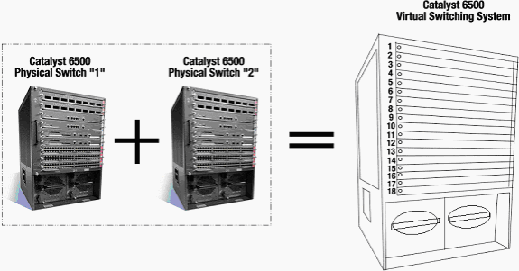
The key enabler of the VSS technology is a special link that binds the two chassis together. This is called a Virtual Switch Link (VSL). VSL carries special control information as well as encapsulates every frame with a header that passes across this link. The VSS concept allows for the combination of two switches into a single logical network entity from the network control plane and management perspective. The VSS appears as a single logical switch or router to the neighboring devices. Within the VSS, one chassis is designated as the Virtual Switch Active and the other is designated as the Virtual Switch Standby.
All control plane functions, such as Management (SNMP, Telnet, SSH, etc.), Layer 2 Protocols (BPDUs, PDUs, LACP, etc.), Layer 3 Protocols (Routing Protocols, etc.), and Software Data path, are centrally managed by the Active Supervisor of the Active Virtual Switch chassis. The supervisor on the Virtual Switch Active is also responsible for programming the hardware forwarding information onto all the Distributed Forwarding Cards (DFCs) across the entire VSS as well as the Policy Feature Card (PFC) on the Virtual Switch Standby supervisor.
From a data plane and traffic forwarding perspective, both switches in the VSS actively forward traffic. The PFC on the Virtual Switch Active supervisor performs central forwarding lookups for all traffic that ingresses the Virtual Switch Active, whereas the PFC on the Virtual Switch Standby supervisor performs central forwarding lookups for all traffic that ingresses the Virtual Switch Standby. The service module integration with VSS is aimed to behave similarly to availability of the service module as if both chassis are a single logical chassis. Therefore, the user can access and activate the modules in either chassis in standalone mode as well as failover mode.
Service Module Integration
The first Cisco IOS Software Release [12.2(33)SXH1] of the VSS included support for the Network Access Module (NAM) service modules. The list of service modules that are supported in the second Cisco IOS Software Release [12.2(33)SXI] of the VSS are:
-
Application Control Engine (ACE)
-
Firewall Services Module (FWSM)
-
Wireless Services Module (WiSM)
-
Intrusion Detection System Services Module (IDSM-2)
-
Shared Port Adapters
| Service Module | Minimum Cisco IOS Release | Minimum Module Release |
|---|---|---|
| Network Analysis Module (NAM-1 and NAM-2) (WS-SVC-NAM-1 and WS-SVC-NAM-2) | 12.2(33)SXH1 | 3.6(1a) |
| Application Control Engine (ACE10 and ACE20) (ACE10-6500-K9 and ACE20-MOD-K9) | 12.2(33)SXI | A2(1.3) |
| Intrusion Detection System Services Module (IDSM-2) (WS-SVC-IDSM2-K9) | 12.2(33)SXI | 6.0(2)E1 |
| Wireless Services Module (WiSM) (WS-SVC-WISM-1-K9) | 12.2(33)SXI | 3.2.171.6 |
| Firewall Services Module (FWSM) (WS-SVC-FWM-1-K9) | 12.2(33)SXI | 4.0.4 |
Redundancy with Service Modules
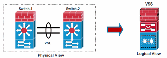
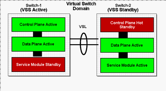
Service modules can be placed in either of the physical chassis that comprise a VSS. For configuration with more than one service module of a given type, configure one in each physical switch for best availability. VSL will carry traffic under normal and failover scenarios, VSL bandwidth must be tuned accordingly.
VSS Active and Standby Supervisor roles are independent of the Service Module redundancy roles, for example an Active Service module can be contained in a VSS Standby chassis and vice-versa.
Application Control Engine (ACE) and Firewall Service Module (FWSM)
High Availability
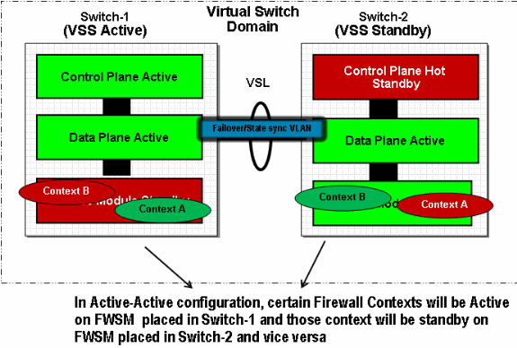
In Active-Standby Redundancy, one of the modules in a VSS system will be Active and second one will be Standby. Secure data traffic is required to be seen by active module.
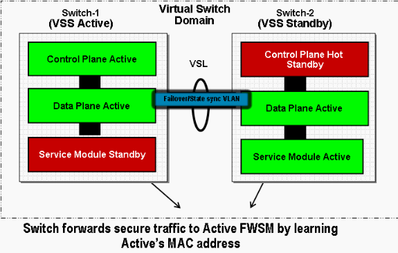
Active-Active Redundancy, both service modules are active and act as a back up for each other.
Packet Flow
-
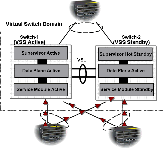
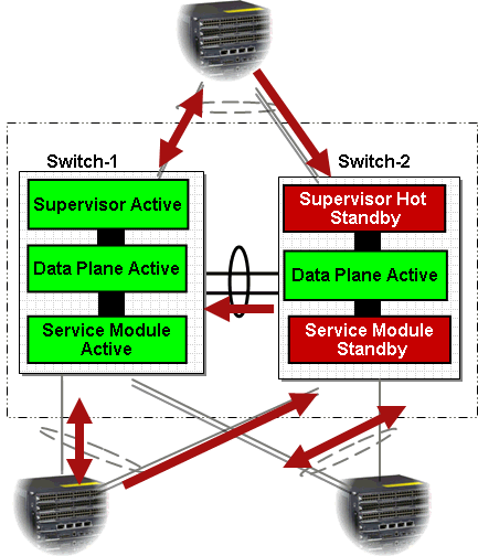
Based on the neighbor device’s load-balancing configuration, it is expected to have traffic transmitted across all interfaces that are part of MultiChassis EtherChannel (MEC).
-
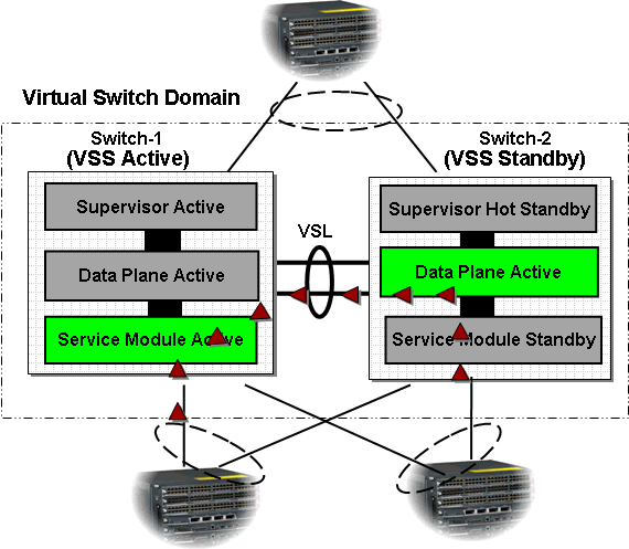
Switch-2 ingress traffic will be redirected to the active service module in Switch-1. Therefore it is expected to have traffic destined to active service module traversing VSL link. It is recommended that the size of the VSL link should be based on expected bandwidth.
-
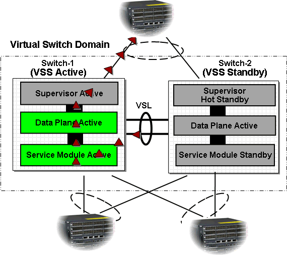
Flows that are arrived on Switch-1 and flows that are redirected from Switch-2 will be processed by active service module and forwarded to next hop device.
For egress traffic, locally connected interfaces are favored in MEC and Layer 3 (L3) Equal-Cost MultiPath (ECMP) interfaces.
Packet Flow Comparison
Traffic Flow in a Standalone System 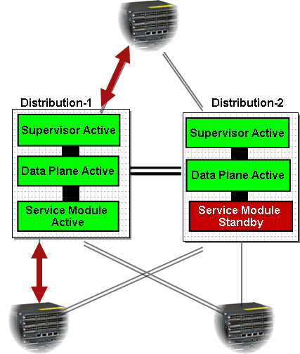
Wireless Services Module (WiSM)
High Availablity
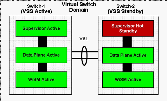
WiSM in VSS works the same as in a standalone chassis. In standalone Catalyst 6500 chassis, when the supervisors go through a Stateful Switchover (SSO), the WiSM line cards are kept intact and packet forwarding resumes in two seconds. Cisco WiSM continues to operate as usual even if a SSO switch over occur. In the VSS, the SSO is in between the two switches. Hence if there is a Cisco WiSM module on the standby switch, packet forwarding can continue during the SSO switch over since the data plane of the standby switch is already fully functional and forwarding.
Multiple WiSMs are supported in a VSS system in Active state. Load-balance achieved by each WiSM serving different set of Access Points (APs). In case active WiSM fails, APs are configured for failover to available WiSMs. The APs leverage the existing LWAPP Discovery and Join process to detect backup controllers for which the APs are configured.
Packet Flow
-
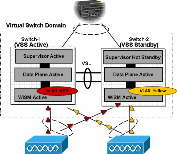
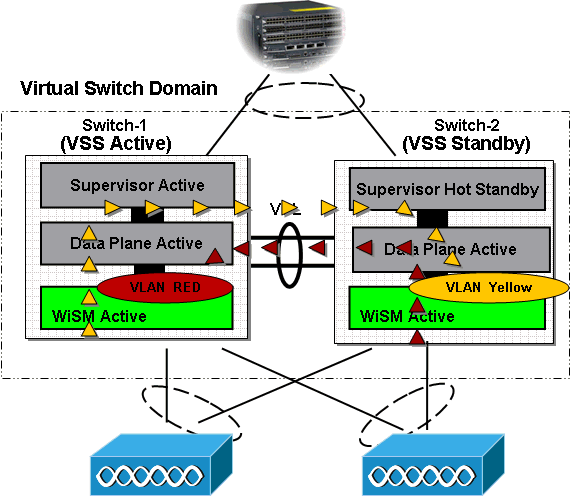
Based on the neighbor device’s load-balancing configuration, it is expected to have traffic across all interfaces that are part of MEC. Therefore, traffic destined to a given WiSM will ingress both physical switches in the VSS.
-
VLAN Red Traffic and VLAN Yellow traffic that is arrived on Switch 1 or 2 will be redirected to Active Service Module of the VLAN. It is expected to see traffic destined to active Service Module traversing VSL link. It is recommended that the size of the VSL link should be based on expected bandwidth.
-
Egress traffic from the the Active WiSM module is forwarded to the next hop device. Locally connected interfaces are favored in MultiChassis EtherChannel and L3 ECMP interfaces.
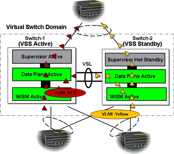
For more information on how to configure a WiSM module in a VSS environment, refer to Cisco WiSM in a Cisco Virtual Switching System Environment.
Intrusion Detection System Services Module (IDSM-2)
High Availability
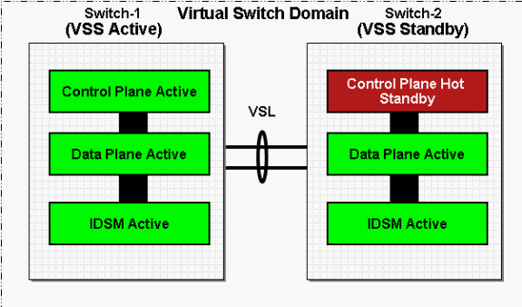
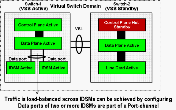
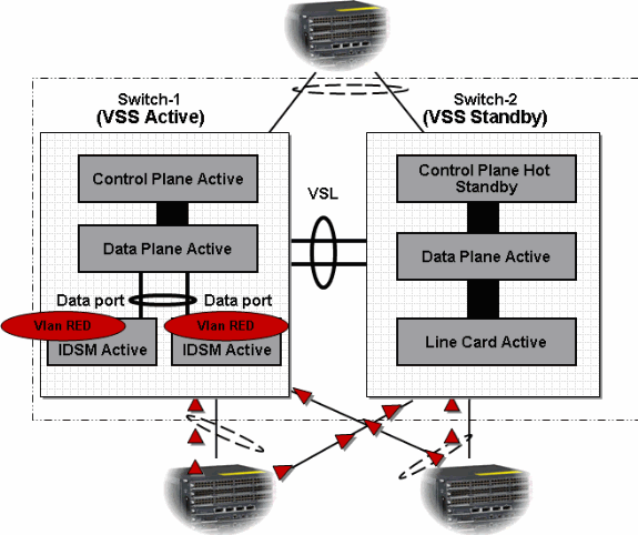
Intrusion Detection System Service Module (IDSM2) does not support session failover mechanisms. However, more than one active IDSM2 is supported in a VSS. Traffic Load-balancing in VSS is similar to standalone containing multiple IDSMs in a single chassis, it is achieved using EtherChannel configuration.
Modes of Operation
Similar to IDSM support available in standalone Cisco Catalyst 6500 system, Promiscuous, In-Line and On-A-Stick modes of operations are supported with VSS as well. If more than one IDSM is installed in each chassis of a VSS system, EtherChannel configuration can be leveraged to load-balance traffic across IDSMs within a chassis.
Packet Flow
-
With configuration of MEC traffic will be load-balanced across all uplink interfaces.
-
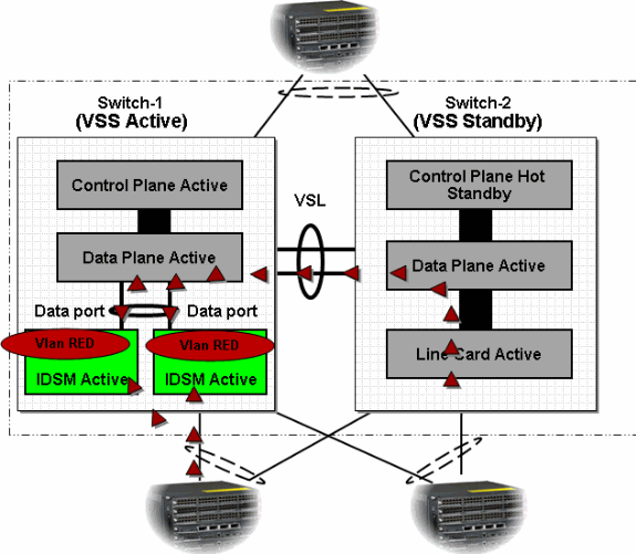
Traffic that needs special attention is copied to IDSMs in hardware using Catalyst features such as SPAN and VLAN capture.
-
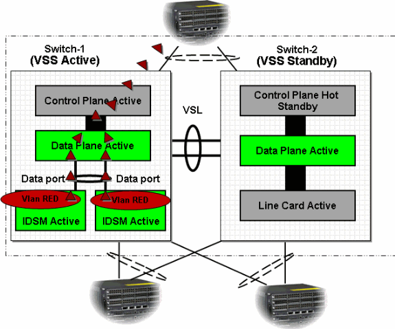
Traffic further processed by IDSM and decision is made to either forward or drop the packets or generate TCP RST to break the connection.
Shared Port Adapters
In VSS, only POS and Gige Shared Port Adapters (SPAs) are supported on SIP400 compared to a standalone system on a Catalyst 6500.
Ethernet SPAs
-
SPA-2x1GE
-
SPA-2x1GE-V2
-
SPA-1x10GE-L-V2
POS SPAs
-
SPA-2xOC3-POS
-
SPA-4xOC3-POS
-
SPA-1xOC12-POS
Note: SPA-5x1GE, SPA-5x1GE-V2 in coming release 12.2(33)SXJ.
Summary
-
Service Module HA modes, Active-Active, Active-Standby, will be supported in VSS. These are independent of the Supervisor HA roles.
-
EtherChannels favor locally attached interfaces. This has implications for Service Modules utilizing internal EtherChannel interface.
-
VSL will carry traffic under normal and failover scenarios, VSL bandwidth must be configured or tuned accordingly.
-
Multiple standalone Service Modules will be supported in VSS.
Related Information
- Configuring Virtual Switching Systems
- Cisco WiSM in a Cisco Virtual Switching System Environment
- Cisco IOS Virtual Switch Command Reference
- Cisco Catalyst 6500 Virtual Switching System 1440 Product Support
- LAN Product Support
- LAN Switching Technology Support
- Technical Support & Documentation - Cisco Systems
Revision History
| Revision | Publish Date | Comments |
|---|---|---|
1.0 |
01-Dec-2013 |
Initial Release |
Contact Cisco
- Open a Support Case

- (Requires a Cisco Service Contract)


 Feedback