Configure System NVE Infra-Vlans in VXLAN BGP EVPN on Nexus 9000 Switches
Available Languages
Download Options
Bias-Free Language
The documentation set for this product strives to use bias-free language. For the purposes of this documentation set, bias-free is defined as language that does not imply discrimination based on age, disability, gender, racial identity, ethnic identity, sexual orientation, socioeconomic status, and intersectionality. Exceptions may be present in the documentation due to language that is hardcoded in the user interfaces of the product software, language used based on RFP documentation, or language that is used by a referenced third-party product. Learn more about how Cisco is using Inclusive Language.
Introduction
This document describes the purpose of the system nve infra-vlans command in Virtual Extensible LAN Border Gateway Protocol Ethernet VPN (VXLAN BGP EVPN) fabrics based on Cisco Nexus 9000 Switches which run the NX-OS Operating System.
When Nexus 9000 switches are configured as VXLAN Leaf Switches also known as VXLAN Tunnel End Points (VTEP) in virtual Port Channel (vPC) domain, you must have a backup Layer 3 Routing adjacency in between them over the vPC peer-link with the use of an interface vlan. This VLAN must be local to the switches, not stretched across the VXLAN fabric and belong to the Default VRF (Global Routing Table).
Ensure the system nve infra-vlans command is in place on Nexus 9000 platforms with CloudScale ASIC to specify the VLAN can act as an uplink and properly forward the frames with VXLAN encapsulation over the vPC peer-link.
Note: This document is not applicable to Cisco Nexus 9000 Switches which run in Application Centric Infrastructure (ACI) mode and managed by the Cisco Application Policy Infrastructure Controller (APIC).
Prerequisites
Requirements
Cisco recommends that you have knowledge of these topics:
- Nexus NX-OS Software
- VXLAN BGP EVPN
Components Used
The information in this document is based on these software and hardware versions:
- Cisco N9K-C93180YC-EX
- NXOS version 7.0(3)I7(6)
The information in this document was created from the devices in a specific lab environment. All of the devices used in this document started with a cleared (default) configuration. If your network is live, ensure that you understand the potential impact of any command.
Note: This document makes use of the terms Leaf Switch, VTEP and ToR interchangeably.
Use Cases
The next use cases show when it is required to configure the system nve infra-vlans command. In all of them, the allocated VLAN 777 needs to be defined as part of the system nve infra-vlans command and be used to instantiate a Layer 3 Routing backup adjacency over the vPC peer-link. This VLAN 777 needs to be part of the Default VRF (Global Routing Table).
Note: These use cases describe the common scenario of an end-host or Routers physically connected directly to the Cisco Nexus 9000 VXLAN Leaf or Border Leaf Switches. Similarly, these use cases apply in case of a Layer 2 Switch or bridge is in between the Nexus 9000 Leaf Switches and the end-host or Routers.
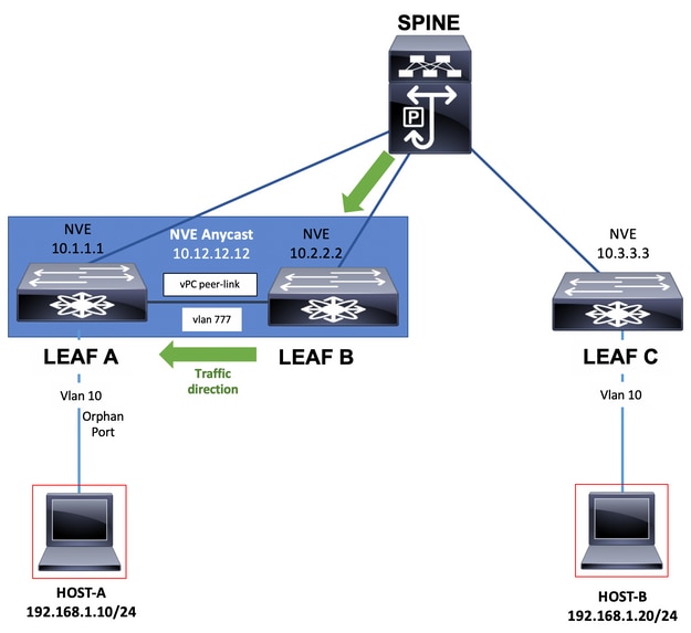
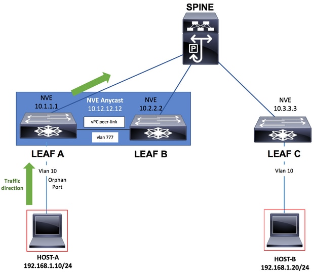
Orphan port on a Leaf Switch in vPC
This use case depicts an end-host inside the fabric (Host-A) connected to a single Cisco Nexus 9000 VXLAN Leaf Switch part of a vPC domain. This is known as an Orphan Port connection. As part of Routing, traffic generated by an end-host connected to any other Leaf Switch in the fabric is destined, in the underlay, to the NVE Anycast IP address (10.12.12.12) own simultaneously by both Leaf Switches in vPC (Switch Leaf A and Switch Leaf B). This is to take advantage of all Leaf-to-Spine uplinks with the use of Equal Cost Multi-Path (ECMP) Routing. In this scenario, after passing through the Spine, VXLAN frames destined to Host-A can hash to Leaf B which has no direct connection to Host-A. The system nve infra-vlans and backup Routing is required for the traffic to traverse the vPC peer-link.
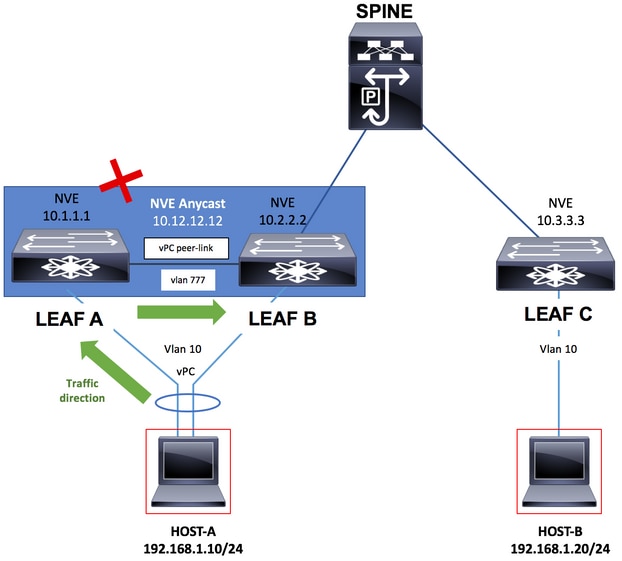
Failure of uplink on a Leaf Switch in vPC
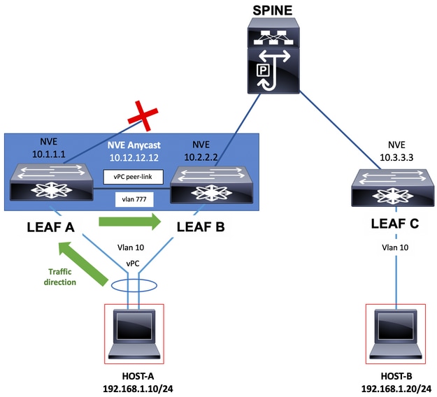
In this use case, the end-host (Host-A) inside the fabric is dual homed to both Cisco Nexus 9000 VXLAN Leaf Switches in a vPC domain. However, in case of failure of all the uplinks on any of the Leaf switches in vPC which can completely isolate it from the Spine switches, the system nve infra-vlans and backup Routing is required for the traffic to traverse the vPC peer-link which is now the only possible path towards the Spine. For instance, the diagram shows Host-A's traffic has hashed its frame to the isolated switch Leaf A. The frame now has to traverse the vPC peer-link.
Border Leaf Switches in vPC
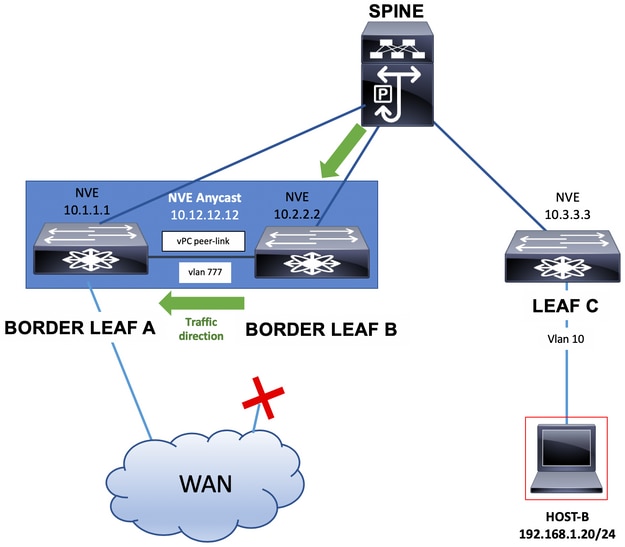
Border Leaf switches which provide connectivity out of the VXLAN fabric by the exchange of network prefixes with External Routers, can be in vPC.
This connectivity to External Routers can abstractly be seen as connectivity to the WAN.
Border Leaf switches with connectivity to the WAN could end up single homed in the case of link failure. In such event the system nve infra-vlans and backup Routing is required for the traffic to traverse the vPC peer-link as shown in the next diagram.
Note: For the next examples, additionally to the VLAN in Global Routing Table, there must be a VLAN part of the Tenant-VRF which base the exchange of network prefixes with the use of Static Routes or a Routing Protocol between the Border Leaf switches over the vPC peer-link. This is required in order to populate the Tenant-VRF Routing Table.
Border Leaf Switches can also advertise interface loopbacks over the vPC peer-link with the use of Static Routes or a Routing Protocol instantiated in a Tenant-VRF. This traffic will be carried over the vPC peer-link as well.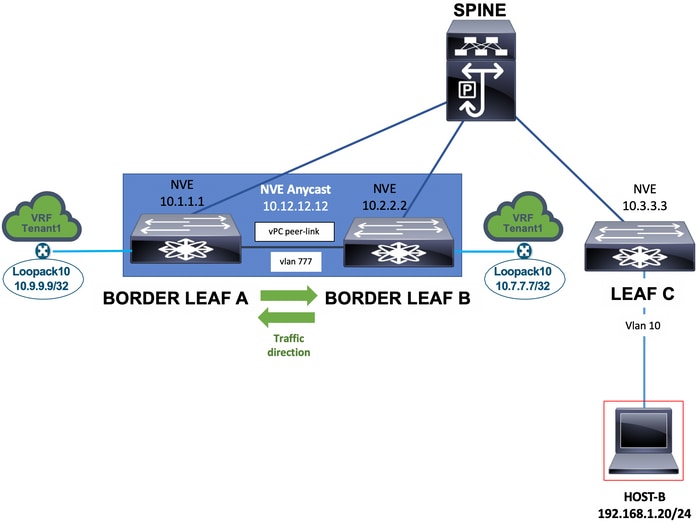
Finally, External Routers single home connected to Border Leaf switches can advertise network prefixes which can be required to have the vPC peer-link in the path of the network traffic as seen in the next diagram.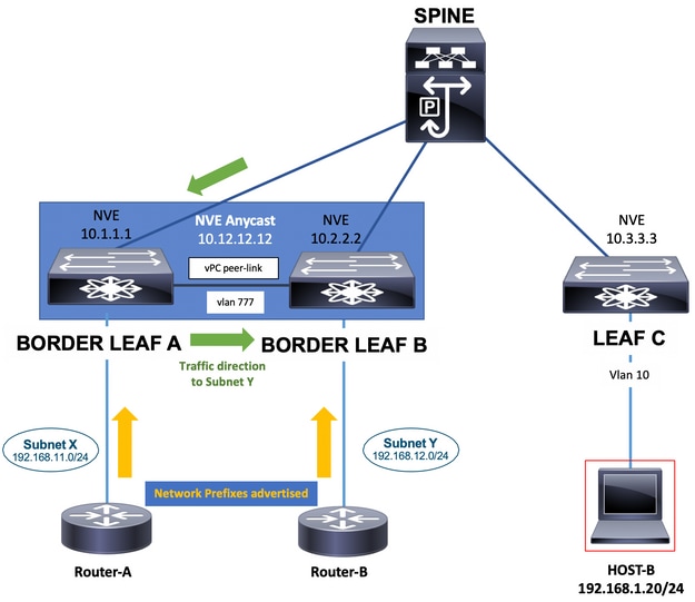
Bud node
In the Bud node use case, there can be a Hardware or Software based VTEP connected to the Cisco Nexus 9000 VXLAN Leaf Switches. This VTEP can send to the Leaf Switches VXLAN encapsulated traffic. The VLAN used for connectivity with this Hardware or Software VTEP must be added to to the system nve infra-vlans command.
In this case, it is VLAN 10 additionally to VLAN 777.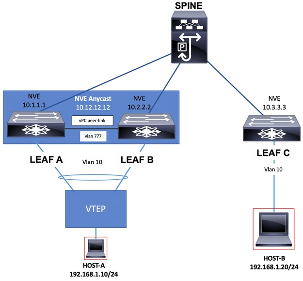
Configure
In this scenario, LEAF A and LEAF B are VTEPs in vPC.
Vlan 777 has been chosen to participate in the underlay Routing Protocol which in this case is Open Shortest Path First (OSPF).
On each LEAF A and LEAF B switches, OSPF has formed an adjacency with the SPINE switch over the uplink and between them over the vPC peer-link.
OSPF or Intermediate System-to-Intermediate System (IS-IS) can be the Routing Protocol in use in the underlay.
Note: No vn-segment command is configured under vlan 777 configuration section. This indicates the vlan is not stretched across the VXLAN fabric and it is local in the Switches.
Add the system nve infra-vlans command in global configuration mode and chose vlan 777 since it is the vlan used for the underlay OSPF adjacency.
Note: The system nve infra-vlans is only required on Nexus 9000 with CloudScale ASIC.
| LEAF A |
|---|
LEAF_A# show ip ospf neighbors OSPF Process ID 1 VRF default Total number of neighbors: 2 Neighbor ID Pri State Up Time Address Interface 10.255.255.254 1 FULL/ - 00:02:52 10.255.255.254 Eth1/6 10.255.255.2 1 FULL/ - 02:16:10 10.1.2.2 Vlan777 LEAF_A# |
| LEAF B |
|---|
LEAF_B# show ip ospf neighbors OSPF Process ID 1 VRF default Total number of neighbors: 2 Neighbor ID Pri State Up Time Address Interface 10.255.255.254 1 FULL/ - 02:21:53 10.255.255.254 Eth1/5 10.255.255.1 1 FULL/ - 02:13:51 10.1.2.1 Vlan777 LEAF_B# |
Note: You must not configure certain combinations of infra-VLANs. For example, 2 and 514, 10 and 522, which are 512 apart.
Network Diagram
Configurations
| LEAF A |
|---|
configure terminal ! hostname LEAF_A ! nv overlay evpn feature ospf feature bgp feature interface-vlan feature vn-segment-vlan-based feature nv overlay feature vpc feature lacp ! vlan 10 name VLAN_10_VRF_RED vn-segment 1000 vlan 100 name L3_VNI_VRF_RED vn-segment 10000 vlan 777 name BACKUP_VLAN_ROUTING_NVE_INFRA ! vpc domain 1 peer-keepalive destination 10.82.140.99 source 10.82.140.98 vrf management peer-switch peer-gateway layer3 peer-router ! interface Ethernet1/1 switchport switchport mode trunk channel-group 1 mode active no shutdown ! interface Port-Channel1 vpc peer-link no shutdown ! |
| LEAF B |
|---|
configure terminal ! hostname LEAF_B ! nv overlay evpn feature ospf feature bgp feature interface-vlan feature vn-segment-vlan-based feature nv overlay feature vpc feature lacp ! vlan 10 name VLAN_10_VRF_RED vn-segment 1000 vlan 100 name L3_VNI_VRF_RED vn-segment 10000 vlan 777 name BACKUP_VLAN_ROUTING_NVE_INFRA ! vpc domain 1 peer-keepalive destination 10.82.140.98 source 10.82.140.99 vrf management peer-switch peer-gateway layer3 peer-router ! interface Ethernet1/1 switchport switchport mode trunk channel-group 1 mode active no shutdown ! interface Port-Channel1 vpc peer-link no shutdown ! |
| LEAF C |
|---|
configure terminal
!
hostname LEAF_C
!
nv overlay evpn
feature ospf
feature bgp
feature interface-vlan
feature vn-segment-vlan-based
feature nv overlay
!
vlan 10
name VLAN_10_VRF_RED
vn-segment 1000
vlan 100
name L3_VNI_VRF_RED
vn-segment 10000
vlan 777
name BACKUP_VLAN_ROUTING_NVE_INFRA
!
fabric forwarding anycast-gateway-mac 000a.000b.000c
!
vrf context RED
vni 10000
rd auto
address-family ipv4 unicast
route-target both auto
route-target both auto evpn
!
interface Ethernet1/1
description TO SPINE
no switchport
medium p2p
ip unnumbered loopback1
ip ospf network point-to-point
ip router ospf 1 area 0.0.0.0
no shutdown
!
interface Ethernet1/49
description TO HOST-A
switchport
switchport access vlan 10
spanning-tree port type edge
no shutdown
!
interface loopback0
description NVE LOOPBACK
ip address 10.3.3.3/32
ip router ospf 1 area 0.0.0.0
!
interface loopback1
description OSPF & BGP ID
ip address 10.255.255.3/32
ip router ospf 1 area 0.0.0.0
!
interface Vlan100
no shutdown
vrf member RED
no ip redirects
|
| SPINE |
|---|
configure terminal
!
hostname SPINE
!
nv overlay evpn
feature ospf
feature bgp
feature nv overlay
!
interface Ethernet1/5
  description TO LEAF A
  no switchport
  medium p2p
  ip unnumbered loopback1
  ip ospf network point-to-point
  ip router ospf 1 area 0.0.0.0
  no shutdown
!
interface Ethernet1/6
  description TO LEAF B
  no switchport
  medium p2p
  ip unnumbered loopback1
  ip ospf network point-to-point
  ip router ospf 1 area 0.0.0.0
  no shutdown
!
interface Ethernet1/1
  description TO LEAF C
  no switchport
  medium p2p
  ip unnumbered loopback1
  ip ospf network point-to-point
  ip router ospf 1 area 0.0.0.0
  no shutdown
!
interface loopback1
  description OSPF & BGP ID
  ip address 10.255.255.254/32
  ip router ospf 1 area 0.0.0.0
!
router ospf 1
  router-id 10.255.255.254
!
router bgp 65535
  router-id 10.255.255.254
  address-family ipv4 unicast
  address-family l2vpn evpn
    retain route-target all
  neighbor 10.255.255.1
    remote-as 65535
    update-source loopback1
    address-family ipv4 unicast
    address-family l2vpn evpn
      send-community
      send-community extended
      route-reflector-client
  neighbor 10.255.255.2
    remote-as 65535
    update-source loopback1
    address-family ipv4 unicast
    address-family l2vpn evpn
      send-community
      send-community extended
      route-reflector-client
  neighbor 10.255.255.3
    remote-as 65535
    update-source loopback1
    address-family ipv4 unicast
    address-family l2vpn evpn
      send-community
      send-community extended
      route-reflector-client
!
end
|
Verify
Run the command show system nve infra-vlans and ensure the vlan is shown under Currently active infra Vlans.
| LEAF A |
|---|
LEAF_A# show system nve infra-vlans Currently active infra Vlans: 777 Available Infra Vlans : 7-264,266-511,519-776,778-1023,1031-1288,1290-1535,1543-1800,1802-2047,2055-2312,2314-2559,2567-2824,2826-3071,3079-3336,3338-3583,3591-3848,3850-3967 *Configuration of two infra-vlans which are 512 apart is not allowed. Ex: 4, 516 are not allowed to be configured together LEAF_A# |
| LEAF B |
|---|
LEAF_B# show system nve infra-vlans Currently active infra Vlans: 777 Available Infra Vlans : 7-264,266-511,519-776,778-1023,1031-1288,1290-1535,1543-1800,1802-2047,2055-2312,2314-2559,2567-2824,2826-3071,3079-3336,3338-3583,3591-3848,3850-3967 *Configuration of two infra-vlans which are 512 apart is not allowed. Ex: 4, 516 are not allowed to be configured together LEAF_B# |
Note: Layer 3 physical interfaces is the recommendation to be used as uplinks to transport VXLAN traffic in the fabric. Layer 3 sub-interfaces are not supported. To use interface vlans to transport VXLAN traffic, ensure the vlan is also identified with the command system nve infra-vlans over the vPC peer-link.
Troubleshoot
In the event that LEAF A switch suffers from an uplink failure and it no longer connects directly to the SPINE switch, reachability can still be accomplished with the infra-vlan over the vPC peer-link used as a backup uplink towards the SPINE switch.
| LEAF A |
|---|
LEAF_A# show mac address-table vlan 10
Legend:
* - primary entry, G - Gateway MAC, (R) - Routed MAC, O - Overlay MAC
age - seconds since last seen,+ - primary entry using vPC Peer-Link,
(T) - True, (F) - False, C - ControlPlane MAC, ~ - vsan
VLAN MAC Address Type age Secure NTFY Ports
---------+-----------------+--------+---------+------+----+------------------
* 10 0000.0000.000a dynamic 0 F F Eth1/54
C 10 0000.0000.000b dynamic 0 F F nve1(10.3.3.3)
G 10 00be.755b.f1b7 static - F F sup-eth1(R)
G 10 4c77.6db9.a8db static - F F vPC Peer-Link(R)
LEAF_A#
|
Revision History
| Revision | Publish Date | Comments |
|---|---|---|
1.0 |
25-Jul-2019
|
Initial Release |
Contributed by Cisco Engineers
- Hector Gustavo Serrano GutierrezCisco TAC Engineer
Contact Cisco
- Open a Support Case

- (Requires a Cisco Service Contract)
 Feedback