Understand How Logical Partitioning Policies and Geolocations Work
Available Languages
Contents
Introduction
This document explains how Geolocations, Geolocation Filters, and Logical Partitioning can be used in countries, such as India, who need to separate their Off-net calls from their On-net calls. The Class of Service provided by Calling Search Spaces (CSSs) and Partitions might not provide the level of granularity that is required in order to comply with certain laws and regulations. You might also find that these same elements are used in Extension Mobility Cross Cluster (EMCC) configurations. Refer to the Cisco Unified Communications Manager Features and Services Guide for Release 7.1(2), which explains how to filter to a more specific location. The geographical components are not discussed further in this document. Rather, the focus of this document is to review how it all works together logistically.
Prerequisites
Requirements
There are no specific requirements for this document.
Components Used
The information in this document was created from the devices in a specific lab environment. All of the devices used in this document started with a cleared (default) configuration. If your network is live, make sure that you understand the potential impact of any command.
Conventions
Refer to Cisco Technical Tips Conventions for information on document conventions.
CUCM Administration of Policies
These major elements can be found on the Cisco Unified Communications Manager (CUCM) (CallManager) CCMAdmin page:
- Device > Phone > Find > Geolocation/Device Pool
- Device > Trunk > Find > Geolocation/Device Pool
- System > Device Pool > Find > Geolocation/Goelocation Filter
- System > Geolocation Configuration
- System > Geolocation Filter
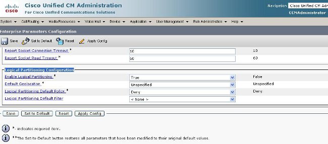
Under CCMAdmin, go to Enterprise Parameters > Logical Partitioning Configuration. There are four parameters that can affect Geolocations and Logical Partitioning. Be aware that:
- All your Device configurations, Device Pool configurations, Logical Partitioning configurations, Geolocations, Filters, and so on must have the Enable Logical Partitioning parameter changed from the default of False to True.
- The Default Policy is set to Deny by default. The no Policy is explicitly defined in the Call Routing > Logical Partition Policy Configuration.
- Devices can be assigned a Default Geolocation even if your Device Geolocation configuration and Device Pool Geolocation configuration is blank.
If you make configuration changes and cannot figure out why it does not function as expected, examine the Geolocation(s) assigned directly to your endpoints, such as phone, as well as your trunks and gateways, such as SIP Trunk. If there is no Geolocation directly assigned to a phone, trunk, or gateway, then examine the Geolocation and Geolocation Filter assigned to the Device Pool(s), respectively. If both are blank, examine the Default Policy listed among the aforementioned Enterprise Parameters.
Now that you know the details assigned to the phone (an Interior device) and a trunk or gateway (a Border device), you can match the Logical Partition Policies. Go to Call Routing > Logical Partition Policy Configuration. Knowledge and comprehension of Policies can be a challenge. One of the goals of this document is to provide examples that are helpful and comprehensive.
Sample Scenario
You configure two Policies named Bangalore and Chennai. Understand that when you pull up the Logical Partitioning Policy Configuration page, it has a name at the top that is always linked to the first of the two Device Types you selected. When you configure the Bangalore Logical Partitioning Policy (Geolocation Policy), then the Allow/Deny relationship always begins with Bangalore Interior or Bangalore Border.
With these two policies, the possible permutations on the Bangalore Policy page include:
- Bangalore Interior to Bangalore Interior
- Bangalore Interior to Bangalore Border
- Bangalore Border to Bangalore Interior
- Bangalore Border to Bangalore Border
- Bangalore Interior to Chennai Interior
- Bangalore Interior to Chennai Border
- Bangalore Border to Chennai Interior
- Bangalore Border to Chennai Border
With these two policies, there are also eight possible permutations on the Chennai Policy page, which include:
- Chennai Interior to Bangalore Interior
- Chennai Interior to Bangalore Border
- Chennai Border to Bangalore Interior
- Chennai Border to Bangalore Border
- Chennai Interior to Chennai Interior
- Chennai Interior to Chennai Border
- Chennai Border to Chennai Interior
- Chennai Border to Chennai Border
Note: There is no need to configure so many policy relationships for various reasons. The relationship logic does not examine direction. Therefore, Bangalore Interior to Chennai Border is the same as Chennai Border to Bangalore Interior. Try to avoid configurations that conflict with each other.
Frequently Asked Questions on Policy Conflicts and Overlap
Q: What happens if there are conflicts or policies that overlap?
A: There is some logic, but it can be difficult to track. The logic is related to the last policy that was added, not a modified policy, but a newly added policy.
If a policy that contained the value Allow is then later changed to Deny, then it remains Deny. The opposite is also true. A policy previously set to Deny, later changed to Allow is an Allow. The Cisco Unified Reporting > Geolocation Policy Report can help you identify policies that overlap.
Q: What if Bangalore Interior to Chennai Border is configured to Allow while Chennai Border to Bangalore Interior is configured to be Deny?
A: If the Chennai Border to Bangalore Interior is the last one added, its policy takes precedence.
Note: Policies only affect Interior-to-Border, Border-to-Interior, and Border-to-Border relationships, not Interior-to-Interior relationships.
With this additional information in mind, the sample policies in this document can be drastically reduced from a combined sixteen entries to seven entries. Remember, Interior-to-Interior is not affected. The Interior-to-Interior and Overlap policies are shown with strikethrough, and therefore, would no longer appear in the list.
The Bangalore Policy page now includes:
-
Bangalore Interior to Bangalore Interior- Interior-to-Interior not affected. - Bangalore Interior to Bangalore Border
-
Bangalore Border to Bangalore Interior- Overlaps with Bangalore Interior to Bangalore Border configured on Bangalore Policy page. - Bangalore Border to Bangalore Border
-
Bangalore Interior to Chennai Interior- Interior-to-Interior not affected. - Bangalore Interior to Chennai Border
- Bangalore Border to Chennai Interior
- Bangalore Border to Chennai Border
The Chennai Policy page now includes:
-
Chennai Interior to Bangalore Interior- Interior-to-Interior not affected. -
Chennai Interior to Bangalore Border- Overlaps with Bangalore Border to Chennai Interior configured on Bangalore Policy page. -
Chennai Border to Bangalore Interior- Overlaps with Bangalore Interior to Chennai Border configured on Bangalore Policy page. -
Chennai Border to Bangalore Border- Overlaps with Bangalore Border to Chennai Border configured on Bangalore Policy page. -
Chennai Interior to Chennai Interior- Interior-to-Interior not affected. - Chennai Interior to Chennai Border
-
Chennai Border to Chennai Interior- Overlaps with Chennai Interior to Chennai Border configured on Chennai Policy page. - Chennai Border to Chennai Border
An IP Phone with a Chennai Geolocation that matches a Chennai Policy is a Chennai Interior device. A SIP trunk with a Chennai Geolocation that matches a Chennai Policy is a Chennai Border device. There is no need to specifically assign the Device-Type. CUCM automatically categorizes trunks, gateways, and phones. If you want the Chennai Interior device (phone) to be able to call out a Chennai Border device (SIP trunk) without the call being rejected, for example, the call receives a fast busy signal, then you must ensure the Chennai Interior to Chennai Border policy is set to Allow, without any policy overlap configured later.
Note: Changes to Device Pools should require that the Device Pools are reset in order for the change to be committed. As this is likely to impact many devices, changes should be configured after hours.
Note: In the CallManager SDI (ccm.txt) traces, you might find that a call can be rejected because of Logical Partitioning (LP) without a Digit Analysis (DA) performed. Here is an example: SIP Invite, Trying, 503 Service Unavailable with no DA in between.
Here is an example of a full rejection message:
09/18/2012 21:53:48.379 CCM|Cdcc::CcRejInd: ccRejInd.c.cv =  -1493172161|
<CLID::KCMCS01-Cluster> <NID::10.50.1.11><CT::2,100,45,1.1290981><IP::10.50.15.127><DEV::>
<LVL::Detailed><MASK::0800>
 ...
  CV=-1493172161 in CcRejInd refers to Logical Partitioning denial as per this
junked Defect CSCsz91044
  ...
  09/18/2012 21:53:48.380 CCM|//SIP/SIPTcp/wait_SdlSPISignal: Outgoing SIP TCP
message to 10.50.15.127 on port 50380 index 90345
  SIP/2.0 503 Service Unavailable
This diagram provides an example of Geolocation and Logical Partitioning.
Figure 1: Network Diagram
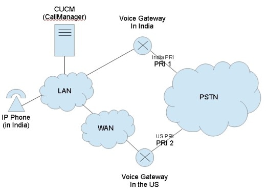
This diagram shows the desired call flow, which is likely because of government regulations to restrict TEHO (Tail-End-Hop-Off) and Toll-Bypass:
- The India IP Phone should be able to call out Primary Rate Interface (PRI) 1 with the rationale that the public switched telephone network (PSTN) access is local.
- The India IP Phone should not be able to call out PRI 2 with the rationale that the PSTN access is not local.
- Likewise, while the India IP Phone should be able to call out PRI 1 and place the call on hold, it should not be able to dial out PRI 2 and place all three parties into a conference.
Setup with the use of the Geolocations and Logical Partitions
This section shows the steps taken in order to setup and configure the Geolocations and Logical Partitions in CUCM.
Step 1: Configure these settings within the Enterprise Service Parameters. Be aware whether you set the Logical Partitioning Default Policy to Deny or Allow. This is important. It is set to Deny for this configuration example.
Figure 2: CUCM Logical Partitioning Configuration
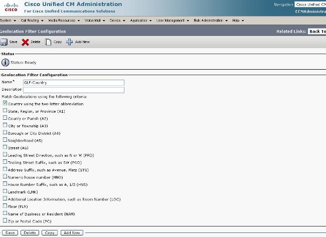
Step 2: Go to the Geolocation Filter Configuration and specify a single filter for this specific configuration. You can specify more if your configuration becomes very advanced. In this case, specify that it match only on Country.
Figure 3: CUCM Geolocation Filter Configuration
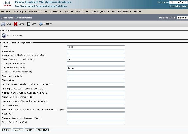
Step 3: Go to the Geolocation Configuration and setup the certain specified locations that it should prefer to filter against. This is very simple and does not have to be configured any more than for what you set your Geolocation Filter, but this example does show some additional configurations.
Figure 4: CUCM List of Geolocations
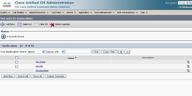
Figure 5: Geolocation Configuration
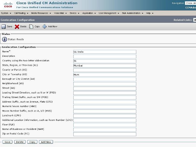
Figure 6: Geolocation Configuration Page 2
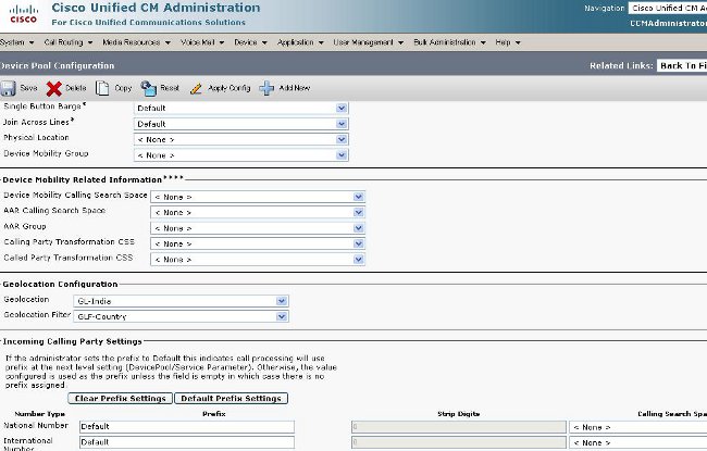
Step 4: Go to the Device Pool Configuration and find the Geolocation Configuration parameters. Set this in the location that the phone is physically located.
Figure 7: Device Pool Configuration
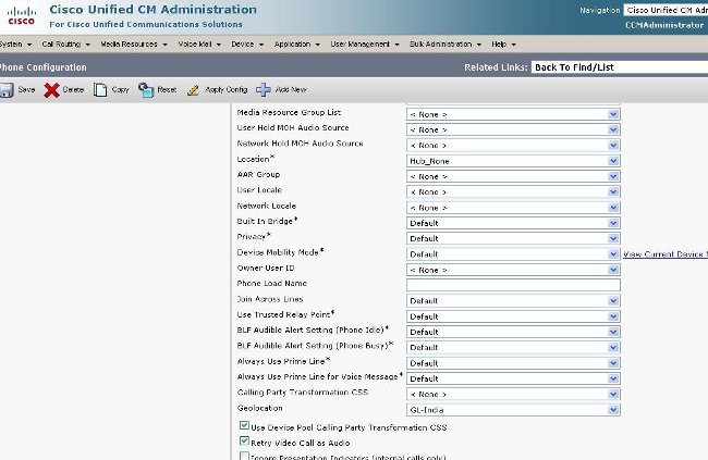
Step 5: Go to the Device Configuration page for the phone and select the location that the phone is located.
Figure 8: Phone Configuration
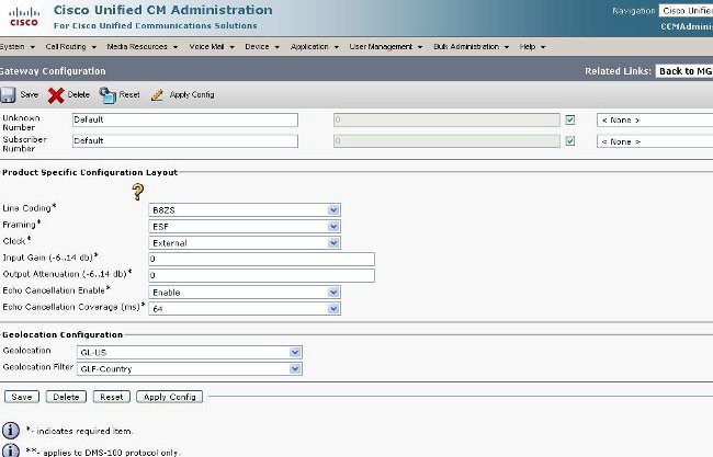
Step 6: Go to the Device Configuration page for the PRI interfaces and configure them as individual units and as if they are the same.
Figure 9: PRI for India
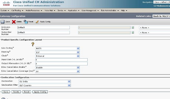
Figure 10: PRI for US
Step 7: This step is the more difficult part in the configuration of the Logical Partition Policies.
Note: You need two policies.
Figure: 11: Logical Partitioning Policy List
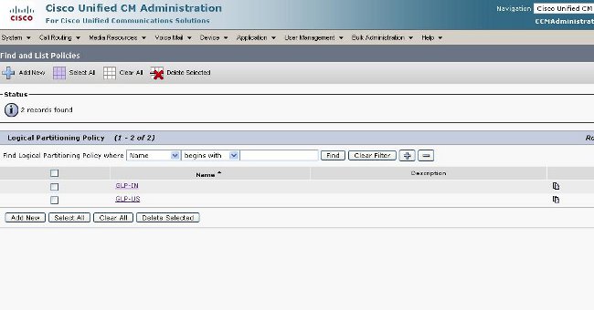
Figure 12: India Policy
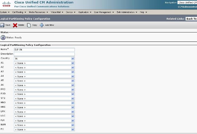
Figure 13: India Policy Continued
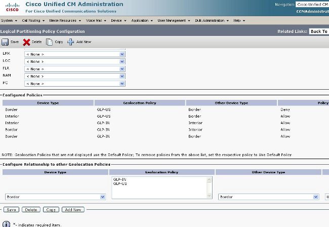
Figure 14: US Policy
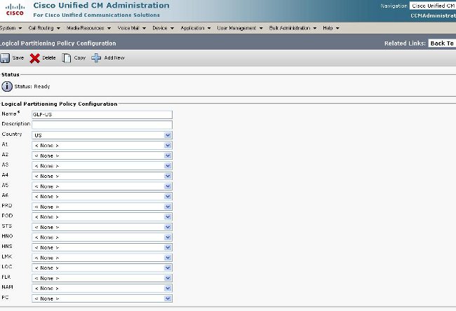
Figure 15: US Policy Continued
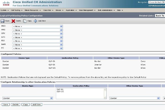
Border and Element Devices
This section explains the meaning of Border and Interior and how to know which device is Border verses Interior.
The terminology used in order to categorize the CUCM devices is based on their function.
- Border Devices ? These devices allow PSTN access or communication to inter-cluster.
- Interior Devices ? These devices are Voice over IP (VoIP) endpoints.
Typical Border devices include:
- Gateway (for example, H.323 Gateway)
- Intercluster trunk (ICT), both gatekeeper-controlled and non-gatekeeper- controlled
- H.225 trunk
- SIP trunk
- Media Gateway Control Protocol (MGCP) port (E1, T1, PRI, BRI, FXO)
Typical Interior devices include:
- Phones (SCCP, SIP, third party)
- VG224 analog phones
- MGCP port (FXS)
- CTI Route Points and CTI Ports
- Cisco Unity Voice Mail (SCCP)
This source of Border and Interior is fixed, based on CUCM device, and is not configurable in CUCM Release 7.1.
Configuration to Allow versus Deny
The entire configuration example in this document was completed with the Enterprise Parameter set to a Deny state. See Figure 2. In some circumstances, you might want to modify this value to Allow and then setup everything that you want to Deny because it is more difficult to do it as this configuration is set up.
For this setup, this is all you need to configure:
- Enterprise Parameters.
- Geolocation Filter.
- Geolocation Configuration.
- Device Pool.
- Geolocation information on the IP Phone.
- Geolocation information on the PRI interfaces (the gateway is MGCP).
- Geolocation Policies (Border/Interior allow/deny configuration) within the Logical Partitioning.
Related Information
Revision History
| Revision | Publish Date | Comments |
|---|---|---|
1.0 |
29-Apr-2013 |
Initial Release |
Contact Cisco
- Open a Support Case

- (Requires a Cisco Service Contract)
 Feedback