Understanding the Cisco IP Phone 10/100 Ethernet In-Line Power Detection Algorithm
Available Languages
Contents
Introduction
One of the challenges IP Telephony has faced is that traditional PBX-based digital phones derive power from the PBX through the phone cable. This allows the phones to operate during times of power outages, provided that the PBX has a battery, a generator backup or both. First generation IP phones required a separate power supply for each phone. In order to maintain phone system availability during a power outage the external power supplies must be connected to an uninterruptible power source. Cisco has introduced a solution to this problem by supplying power to the phone via the same Ethernet cable that carries the data to the phone. This power can be supplied by 10/100 Ethernet blades or modules such as the WS-X6348 that are installed in a chassis or by a separate device such as the WS-PWR-PANEL.
There are currently two different implementations of in-line powered Ethernet ports in Cisco products. The first uses the same two pairs of wire over which the Ethernet signals are carried (pins 1, 2, 3, 6), while the other uses the two unused Ethernet pairs (pins 4, 5, 7, 8). The IEEE 802.3af committee has standardized in-line power over Ethernet in June 2003. For more information with regard to 802.3af, refer to IEEE 802.3af DTE Power via MDI Task Force ![]() .
.
Prerequisites
Requirements
There are no specific prerequisites for this document.
Components Used
This document is not restricted to specific software and hardware versions.
Conventions
For more information on document conventions, refer to the Cisco Technical Tips Conventions.
Products Currently Available for Supplying In-Line Power
There are currently four Cisco products that have the capacity to supply in-line power.
Catalyst 6000 Switch
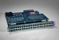
The first product is the WS-X6348 48 port 10/100 line module for the Cisco Catalyst 6000 series switches. The card by itself is only in-line power capable. To provide in-line power, it must also have the WS-F6K-VPWR daughter card installed on it. For information on this card, refer to Catalyst 6500 Series Inline-Power Field-Upgrade Daughter Cards Installation Note. All 48 ports have the capacity to supply power to a phone, provided there is sufficient power available on the Cisco Catalyst 6000 switch in which it resides.

The WS-X6348 supplies in-line power via the "used" Ethernet pairs (pins 1, 2, 3, 6).
For more information on the WS-X6348 module, refer to WS-X6348-RJ45V: 48 Port IP Phone Ethernet In-Line Power Blade for Catalyst 6500/6000 Series Switches.
Catalyst 4006 Switch
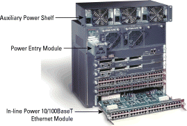
The second product is the WS-X4148-RJ45V 48 port 10/100 line module for the Catalyst 4006 switch. In order to provide in-line power using the Catalyst 4006 switch, you must add on several other components. In-line power is only available on the Cisco Catalyst 4006 and not the Cisco Catalyst 4003 because only the Cisco Catalyst 4006 chassis has the ability to accept the Power Entry Module (PEM) and also has traces on the back-plane which allow the DC power to be supplied to inline-power capable line cards. To enable in-line power on the Cisco Catalyst 4006, you must have the Cisco Catalyst 4000 Auxiliary DC Power Shelf and at least two power supplies (WS-P4603-2PSU). The power shelf can accept up to three power supplies (WS-X4608) for N+1 redundancy. At least two are required for in-line power to work. Special cables (which are included with the power supplies) are used to attach each power supply to the PEM (WS-X4095-PEM). Finally, you must have an in-line power capable line card in the chassis. The WS-X4148-RJ45V is a 48 port in-line power capable 10/100 Ethernet switching module. The picture below does not show the in-line power daughter card that is included with the Cisco Catalyst 4148. It is similar to the daughter-card on the Cisco Catalyst 6000 module. The Cisco Catalyst 4006 switch operates identically to the Cisco Catalyst 6000 switch, in respect to in-line power detection and delivery.

The WS-X4148-RJ45V supplies in-line power via the "used" Ethernet pairs (pins 1, 2, 3, 6).
For more information on the WS-X4148-RJ45V module, refer to Cisco Catalyst 4000 Series Inline Power Solution.
Cisco Catalyst 3524-PWR-XL Switch
The third product is the Cisco Catalyst 3524-PWR-XL (WS-C3524-PWR) switch, which is based on the Cisco Catalyst 3524XL switch.

The WS-C3524-PWR supplies in-line power via the "used" Ethernet pairs (pins 1, 2, 3, 6).
For more information on the Cisco Catalyst 3524-PWR-XL, refer to 3524-PWR XL: Catalyst 3524-PWR XL Stackable 10/100 Ethernet Switch.
Note: The Catalyst 3524-PWR-XL has reached end of sale. As an alternative, use the Catalyst 3550. Refer to Cisco Catalyst 3550 Series Switches.
In-Line Power Patch Panel (WS-PWR-PANEL)
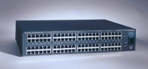
Finally, there is the standalone in-line power patch panel, WS-PWR-PANEL, which requires an external switch to provide the Ethernet connectivity. The in-line power patch panel will supply power "mid-span," that is it connects between the Ethernet switch and the phone. The in-line power patch panel is a completely hardware-based solution and has no software or firmware that can be changed or upgraded in the field.

The WS-PWR-PANEL supplies power using the "unused" pairs (pins 4, 5, 7, 8).
For more information on the WS-PWR-PANEL, refer to the Catalyst Inline Power Patch Panel data sheet.
IEEE 802.3af standard-compliant Power over Ethernet
Cisco now offers IEEE 802.3af standard-compliant Power over Ethernet (PoE) options for its Intelligent Catalyst switching portfolio. IEEE 802.3af compliance is delivered in new PoE 10/100/1000 and 10/100 modules on the Cisco Catalyst 6500 Series and Cisco Catalyst 4500 Series modular chassis; new PoE 10/100 Cisco Catalyst 3750 Series and Catalyst 3560 Series fixed-configuration switches. For more information, refer to Power Over Ethernet Solutions.
The Cisco Catalyst switches that support IEEE 802.3af standard-compliant PoE also support Cisco's pre-standard PoE implementation and are backwards compatible with Cisco's existing end devices, such as IP Telephones and Wireless access points. But the Cisco Catalyst switches that only support the pre-standard PoE implementation are not able to power up IEEE 802.3af end-points.
Detecting that an IP Phone is Connected to a 10/100 Ethernet Port
All the previously listed products rely on a phone-discovery algorithm before the power is supplied to a phone. This algorithm ensures that the switch does not supply power to a device that is not able to accept in-line power. The phone-discovery algorithm used by Cisco Catalyst switches is different than the algorithm used by the WS-PWR-PANEL. Both of these algorithms are explained in this section.
Note: It is not possible to provide a detailed explanation of the phone-discovery algorithms because certain aspects of them are proprietary.
Cisco Catalyst Switches
This table explains the parameters available on the three platforms to enable or disable the supply of power to the ports.
| In-Line Power Modes for Catalyst Switches | ||
|---|---|---|
| auto | Phone-discovery algorithm is operational | Cisco Catalyst 4006, 6000, and 3500XL |
| off | Phone-discovery algorithm is disabled | Cisco Catalyst 4006 and 6000 |
| never | Phone-discovery algorithm is disabled | Cisco Catalyst 3500XL |
Note: There is no such thing as an 'on' mode on any of these devices. This should protect customers from accidentally damaging any Ethernet network interface card (NIC) cards in devices that do not expect to receive power from the network.
The following method for detecting that a Cisco IP Phone is connected to a 10/100 Ethernet port is used by the Cisco Catalyst 6000, Cisco Catalyst 4000, and Cisco Catalyst 3524-PWR-XL Switches.
-
The port starts the phone-discovery algorithm by sending a special Fast Link Pulse (FLP) signal to any device that might be connected to it.
-
The port waits to see if the special FLP signal is forwarded back by a connected device. The only devices that are designed to do this are devices that expect to receive in-line power.
-
If a Cisco 79xx IP Phone is connected to the 10/100 Ethernet port, it will forward the special FLP signal back to the 10/100 Ethernet port on the Cisco Catalyst switch. It is capable of doing this because it has a special relay that connects its Ethernet receive pair with its Ethernet transmit pair. This relay is closed when no power is being supplied to the phone. Once power is supplied, this relay remains in an open state.
-
Now that the Cisco Catalyst switch has determined that it needs to power the port (the special FLP signal was received back from the attached Cisco IP Phone), the Network Management Processor (NMP) is queried to determine if there is any power available to power the IP phone. Since the NMP does not know how much power the Cisco IP Phone will need, it uses the configured default power allocation. Later on it will adjust this allocation based on what the attached Cisco IP Phone tells the switch it really needs.
-
The port then provides power to the Cisco IP Phone over pairs 1 and 2 as a common mode current.
-
The port is taken out of phone-discovery mode and changed to normal 10/100 Ethernet auto-negotiation mode.
-
The instant that the switch applies power to the port, the relay inside the phone opens and power begins to flow to the Cisco IP Phone.
-
At this point a 'wait for link' timer in the switch starts also. The phone has five seconds to establish link integrity on its Ethernet port. If the switch does not detect link integrity on the port within five seconds, it will shut off power to the port and start the phone-discovery process all over again. The switch has to wait at least five seconds so that the switch has enough time to detect all devices.
-
If the switch detects a link within the five second window, it will continue to supply power to the Cisco IP Phone until it detects a link down event.
-
Once the phone has booted up, it will send a CDP message with a Type, Length, Value object (TLV) that tells the switch how much power it really needs. The NMP sees this and adjusts the power allocation for the port accordingly.
Note: Only the Cisco Catalyst 6000 switch keeps track of how much power has been allocated for each device. The Cisco Catalyst 4006 and the Cisco Catalyst 3500XL switches have enough power available to supply Cisco IP Phones on every port.
In-Line Power Patch Panel
The In-line Power Patch Panel (IPPP) uses the unused Ethernet pairs to provide in-line power. The IPPP has four rows of RJ-45 connectors each with 24 ports in a row. The top two rows are the powered ports used to connect to the end device (for example, a Cisco 79xx IP Phone). The bottom two rows are used to connect to the switch which will be providing the Ethernet connectivity.
Internally, the IPPP directly connects the Ethernet pairs from the bottom switch port that corresponds to the phone port on the top. The in-line power patch panel does not interfere with pins 1, 2, 3, and 6 in any way. It does not monitor link and does not care about speed/duplex, because it is completely passive.
The phone discovery algorithm for the IPPP is similar to the method used on Cisco Catalyst switches as explained in the previous section. It relies on the fact that the phone will loop back a special signal that the IPPP sends on its ports. In this case, however, the unused pins 4, 5, 7, and 8 are used to detect Cisco IP Phones. If a Cisco IP Phone is detected, these pins (wire pairs) are also used to provide power.
This method to detect a Cisco IP Phone is connected to a 10/100 Ethernet port is used by the IPPP (WS-PWR-PANEL):
-
The IPPP starts the phone discovery sequence at port 1.
-
The IPPP sends a 347 kHz loopback tone out port 1. The IPPP listens for 50 ms to determine if the loopback tone is forwarded back by a device that is connected to the port. Only devices that are expected to receive power on these pins, forward the loopback tone to the sending device (the IPPP in this case). The IPPP must detect 16 transitions within a 50 ms-period of time to verify that it senses the correct loop back tone and not an anomaly.
-
If the IPPP verifies that this received signal is the correct one, power is enabled on the port. If the signal is not correct the IPPP moves on to the next port and starts the process over again.
-
The IPPP continuously cycles through the ports repeating the above steps for each port.
-
Each port that supplies power is polled for 50 ms every 600 ms to ensure there is still a device attached. This ensures that power is turned off at the port if the device that required it has been disconnected.
Related Information
- WS-X6348-RJ45V: 48 Port IP Phone Ethernet In-Line Power Blade for Catalyst 6500/6000 Series Switches
- Cisco Catalyst 4000 Series Inline Power Solution
- 3524-PWR XL: Catalyst 3524-PWR XL Stackable 10/100 Ethernet Switch
- Catalyst Inline Power Patch Panel
- Understanding IP Phone In-Line Power Provisioning on the Catalyst 6500/6000 Switch
- Voice Technology Support
- Voice and Unified Communications Product Support
- Troubleshooting Cisco IP Telephony

- Technical Support & Documentation - Cisco Systems
Contact Cisco
- Open a Support Case

- (Requires a Cisco Service Contract)
 Feedback