Using Analogue E&M Ports to Interface to Overhead Paging Systems
Available Languages
Contents
Introduction
This document details the background theory and configurations that allow a router Ear and Mouth (E&M) voice port to interface to an overhead paging system.
Prerequisites
Requirements
Ensure that you meet these requirements before you attempt this configuration:
-
Analog E&M signaling theory and router voice port operation
-
Cisco IOS® configuration and Cisco CallManager configuration
Components Used
The information in this document is based on these software and hardware versions:
-
Cisco 2610 Router
-
Cisco IOS version 12.2.7a with an IP Plus feature set
-
NM-2V voice carrier card and a VIC-2E/M (E&M Voice Interface Card (VIC))
-
External paging amplifier
The information in this document was created from the devices in a specific lab environment. All of the devices used in this document started with a cleared (default) configuration. If your network is live, make sure that you understand the potential impact of any command.
Conventions
Refer to Cisco Technical Tips Conventions for more information on document conventions.
Background Information
Many sites with an existing PBX also have a paging system which allows users to call an extension on the PBX that forwards the audio broadcast to overhead loudspeakers. This concept is useful in workshops, parking lots, and open plan areas where a called party is not near a telephone handset. PBX manufacturers can provide dedicated line cards that interface with external paging amplifiers. These PBX paging cards have an isolated audio output, which prevents faults on the paging amplifier that results in damage to the PBX, and a control or relay output that is used to activate the paging amplifier.
As IP-based PBXs and Voice over IP (VoIP) networks become more common, the need to integrate voice-equipped routers into legacy installations is apparent. New paging systems are available. These systems use loop start trunks that interface directly to PBX extension ports and have Voice Operated Relays (VOX) that control the paging amplifiers. Many customers do not wish to purchase new interfaces or replace existing hardware as they transition to IP-based systems. Fortunately, Cisco voice products are flexible enough to cover many of these cases. This document details the method of how to use analog E&M voice interfaces to provide an audio and control output to an interface with an external paging amplifier. Many dedicated PBX paging cards are based on normal PBX E&M line cards.
The difference between a conventional two wire telephone interface, such as Foreign Exchange Station or Office (FXS or FXO), and an E&M interface is that the E&M interface has wires that pass the audio signals plus additional wires to act as an input (to sense an incoming call) or an output (to indicate an outgoing call). These control leads are normally called the E lead (input) and the M lead (output). The signaling leads can be controlled if you connect them to the ground, switch a negative 48Volt DC source, or complete a current loop between the two devices. This depends on the type of E&M interface.
E&M interfaces normally have the option of two or four wire operation. Rather than referring to the total number of physical connections on the port, two or four wire operation relates to the how audio is passed between the devices. Two wire operation means the audio signals that transmit and receive are passed through a single pair of wires (one pair equals two wires). Four wire operation separates the direction of the signal and uses one pair to transmit and another pair to receive audio.
By default, Cisco E&M ports use wink start signaling. Wink start operation dictates that when the voice port goes off hook (E leads the state changes from on hook to off hook), it expects to receive a 200 millisecond wink (on hook/off hook/on hook) transition on the M lead as the acknowledgement allows digits to be sent. The E lead stays in the off hook condition for the duration of the call.
A simpler form of E&M signaling is called immediate start. In this mode, when the voice port goes off hook (E lead changes from on hook to off hook), there is a brief pause. The router then sends the digits without any acknowledgment from the external device. As with wink start, the E lead stays in the off hook condition for the duration of the call.
When the voice port is configured as two wire with immediate start, an outgoing call (from the IP side toward the external device) makes the E lead change from an open circuit, to a short circuit, to the ground. Control leads can be used to switch a relay or push-to-talk control and the audio path opened on the transmit/receive (T/R) leads.
Configure
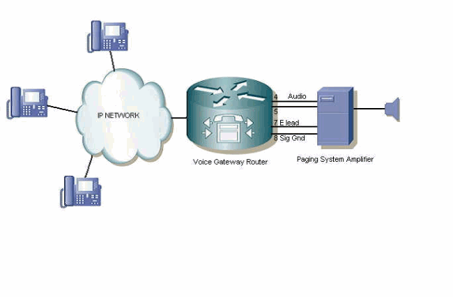
In this example, the customer has a requirement to interface an older paging system into a new Cisco CallManager installation. A Cisco 2610 Router with an E&M VIC is used. The paging amplifier has an audio input and an external push-to-talk control input. These interface pinouts are used between the router E&M voice port and the amplifier:
T1 (Pin 4) ---------------- Microphone audio input
R1 (Pin 5) ---------------- Microphone audio input
E lead (Pin 7) ------------ Push-to-talk control input
Ground (Pin 8) ------------ Push-to-talk control input
The router E&M voice port needs to be configured as a two wire, type 5, with immediate start operation.
The Cisco CallManager needs the Cisco 2610 Router to be configured as a H323 gateway device. The extension number for the paging port is defined under the Cisco CallManager Route Pattern Configuration page, which points to the Cisco 2610 H323 gateway.
When the number for the paging system is dialed, a VoIP call is made between the IP handset to the E&M port on the gateway router. The voice port goes off hook. This is indicated by the E lead on pin 7 that goes from open circuit to closed circuit (with respect to the ground on Pin 8). This off hook condition activates the control input of the pager system and the audio is sent on pins 4 and 5 of the voice port.
If you assume a paging access number of 5555, the gateway router voice port and dial peer configuration look similar to that found in the Configuration section of this document.
Note: Use the Command Lookup Tool (registered customers only) to find more information on the commands used in this document.
Network Diagram
This document uses this network setup:

Configuration
This document uses this configuration:
| Router Voice Port and Dial Peer Configuration |
|---|
! voice-port 1/0/0 operation 2-wire !--- Only use pins 4 and 5 for audio. type 5 !--- Type 5 operation, the most basic mode. signal immediate !--- Immediate start operation. auto-cut-through !--- Send immediate answer back to the VoIP network. ! ! dial-peer voice 5555 pots destination-pattern 5555 !--- Match on 5555 access code. port 1/0/0 !--- Send the call on E&M port 1/0/0. forward-digits none !--- Do not send any digits out of the port. ! |
Note: Make sure you understand that this configuration only works for Analog E&M Ports. Do not try to use this configuration with Analog FXS/FXO Ports to interface to an overhead paging system. If you do, your system can be seriously damaged.
Verify
Use this section to confirm that your configuration works properly.
The Output Interpreter Tool (registered customers only) (OIT) supports certain show commands. Use the OIT to view an analysis of show command output.
In order to confirm the configuration and settings of the voice port, the show voice port <card/slot/port> command provides information about the status of the voice ports of the router, as shown in this example:
Paging_Router#show voice port 1/0/0

recEive And transMit 1/0/0 Slot is 1, Sub-unit is 0, Port is 0
   Type of VoicePort is E&M
   Operation State is DORMANT
   Administrative State is UP
   No Interface Down Failure
   Description is not set
   Noise Regeneration is enabled
   Non Linear Processing is enabled
   Non Linear Mute is disabled
   Non Linear Threshold is -21 dB
   Music On Hold Threshold is Set to -38 dBm
   In Gain is Set to 0 dB
   Out Attenuation is Set to 0 dB
   Echo Cancellation is enabled
   Echo Cancellation NLP mute is disabled
   Echo Cancellation NLP threshold is -21 dB
   Echo Cancel Coverage is set to 8 ms
   Playout-delay Mode is set to default
   Playout-delay Nominal is set to 60 ms
   Playout-delay Maximum is set to 200 ms
   Playout-delay Minimum mode is set to default, value 40 ms
   Playout-delay Fax is set to 300 ms
   Connection Mode is normal
   Connection Number is not set
   Initial Time Out is set to 10 s
   Interdigit Time Out is set to 10 s
   Call Disconnect Time Out is set to 60 s
   Ringing Time Out is set to 180 s
   Wait Release Time Out is set to 30 s
   Companding Type is u-law
   Region Tone is set for US

 Analog Info Follows:
   Currently processing none
   Maintenance Mode Set to None (not in mtc mode)
   Number of signaling protocol errors are 0
   Impedance is set to 600r Ohm
   Station name None, Station number None
   Translation profile (Incoming):
   Translation profile (Outgoing):

 Voice card specific Info Follows:
   Operation Type is 2-wire
   E&M Type is 5
   Signal Type is immediate
   Dial Out Type is dtmf
   In Seizure is inactive
   Out Seizure is inactive
   Digit Duration Timing is set to 100 ms
   InterDigit Duration Timing is set to 100 ms
   Pulse Rate Timing is set to 10 pulses/second
   InterDigit Pulse Duration Timing is set to 750 ms
   Clear Wait Duration Timing is set to 400 ms
   Wink Wait Duration Timing is set to 200 ms
   Wait Wink Duration Timing is set to 550 ms
   Wink Duration Timing is set to 200 ms
   Delay Start Timing is set to 300 ms
   Delay Duration Timing is set to 2000 ms
   Dial Pulse Min. Delay is set to 140 ms
   Percent Break of Pulse is 60 percent
   Auto Cut-through is disabled
   Dialout Delay is 300 ms
   Paging_Router#
Troubleshoot
Use this section to troubleshoot your configuration.
Monitor the Voice Port Signaling and Audio Outputs
Complete these instructions in order to monitor the voice port signaling and audio outputs:
-
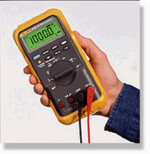
Use a multimeter to measure continuity (cable test, ohms or resistance setting) in order to verify the operation of the E&M port.
If a voice call is placed to the E&M port, the E lead (pin 7) is switched from open circuit to ground (pin 8), and the meter shows a change from high resistance to zero resistance. The E lead switching to ground can be seen by the paging amplifier as a push-to-talk signal. It then broadcasts the audio signal coming in on the audio pairs. This is an example of a typical digital multimeter:

-
Check the voice port audio output with a telephone technician test set (sometimes called a 'Butt Set" or 'Buttinski').
Any outgoing audio can be heard on the earpiece of the test set. This confirms if the router sends a signal to the paging amplifier. The monitor leads of the Butt set are clipped across the T and R wires (pins 4 and 5) on the router voice port. This is an example of a typical telephone test handset:

Refer to the Analog Signaling (E & M, DID, FXS, FXO) Technical Support Page for more information on E&M interfaces and signaling.
Related Information
Revision History
| Revision | Publish Date | Comments |
|---|---|---|
1.0 |
10-Nov-2006 |
Initial Release |


 Feedback