Configure Q.SIG PRI Trunks between Call Manager and Avaya S8700/G650 with Unity Voice Mail Integration
Available Languages
Contents
Introduction
The objective of this document is to provide Cisco customers and business partners with the steps to configure Q.SIG PRI trunks between the Cisco Call Manager and the Avaya S8700/G650. Also, this document details steps for how to add Cisco Unity on the Cisco Call Manager platform in order provide voice mail support for both Cisco and Avaya IP phones. This is particularly important in situations where IP-PBX interoperability and voice mail integration are required. The Avaya configuration screen captures were created with the standard Emulation tool. As an alternative, you can also use the Avaya Site Administration (ASA) tool for configuration tasks on the Avaya S8700/G650. The output display is the same in both cases. This IP-PBX interoperability and voice mail integration document is intended for external use.
Prerequisites
Requirements
There are no specific requirements for this document.
Components Used
The information in this document is based on these software and hardware versions:
-
The Avaya IP-PBX system used is the Avaya S8700/G650 running Avaya Communication Manager 2.0. The Q.SIG feature set comes standard with this software version.
-
The Avaya IP Phones used in this document are the 4610SW and 4620 running Phone Firmware Version 2.01.
-
Cisco Call Manager 4.1.(2) was used in order to control the 3745 Media Gateway Control Protocol (MGCP) gateway with the NM-HDV module, running Cisco IOS® version 12.2.15ZJ3. Tests were also repeated with Cisco IOS® version 12.3.8.T5.
-
Cisco Unity running version 4.0(4) SR1 was used for the voice mail integration testing.
The information in this document was created from the devices in a specific lab environment. All of the devices used in this document started with a cleared (default) configuration. If your network is live, make sure that you understand the potential impact of any command.
Conventions
Refer to Cisco Technical Tips Conventions for more information on document conventions.
Test Setup
The Avaya IP-PBX system used was the Avaya S8700/G650 running Avaya Communication Manager 2.0. The Q.SIG feature set comes standard with this software version. The AvayaIP Phones used were the 4610SW and 4620 running Phone Firmware Version 2.01. On the Cisco side, Cisco Call Manager 4.1.2 was used to control the 3745 MGCP gateway with the NM-HDV module, running Cisco IOS® version 12.2.15ZJ3. Tests were also repeated with Cisco IOS® version 12.3.8.T5. Cisco Unity running version 4.0(4) SR1 was used for the voice mail integration testing.
Test Topology
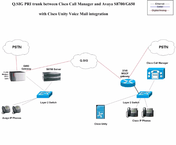
Interoperability between Cisco and Avaya IP-PBX Systems
The next sections provide procedures and screen captures to help you configure the Q.SIG trunk between an Avaya S8700/G650 running Avaya Communication Manager 2.0 and a Cisco Call Manager platform running Call Manager version 4.1(2) with the Cisco 3745 MGCP device that provides the physical ISDN PRI connection to the Avaya S8700/G650.
Procedure on Avaya S8700/G650 IP-PBX system
Complete these steps:
-
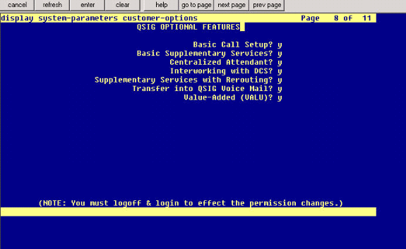
Login to the S8700 server. Run the display system-parameters customer command in order to ensure that all the necessary Q.SIG features are enabled on the S8700 server.
-
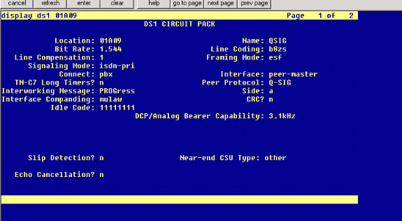
Configure the DS-1 card for Q.SIG PRI.
-
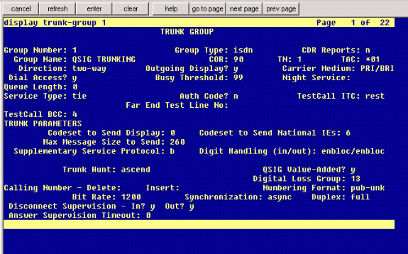
Configure a trunk group. Type add trunk-group # where # is the desired trunk.
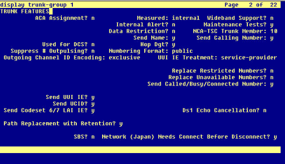
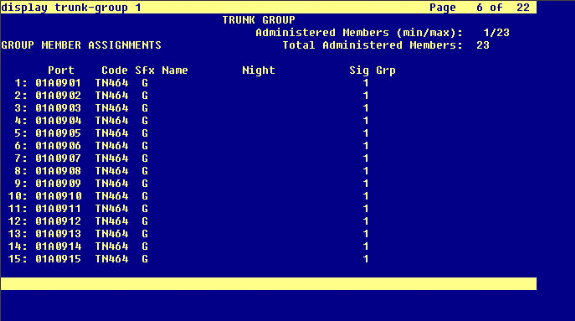
The next three screen captures relate to the trunk configuration. Once the trunk group is created, add the 23 DS0 channels to the group. This is an example of the port assignment: 01A0901 means: Gateway# 1, Cabinet A, Slot# 9, DS0 channel# group1.
-
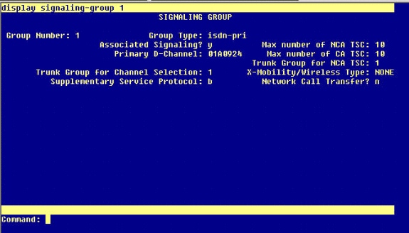
Add the signaling group and point to the trunk group created earlier.
-
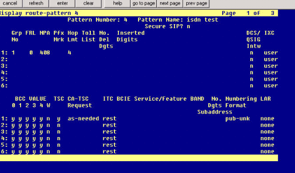
Add the route pattern and point it to the signaling group. In this example, the route pattern 4 points to signaling group# 1 that was created in step 4.
-
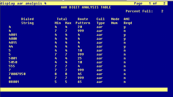
Add an entry into the AAR table in order to use the route pattern you created to route calls. In this example, calls to Cisco IP phone extension 4XXX use the AAR table entry starting with 4, which in turn points to route pattern # 4.
-
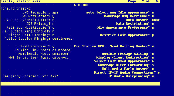
Ensure caller ID is enabled on each IP phone to send calling party name.
Procedure on Cisco Call Manager
Complete these steps:
-
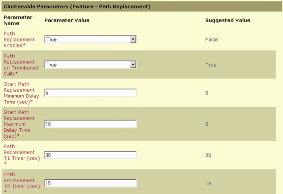
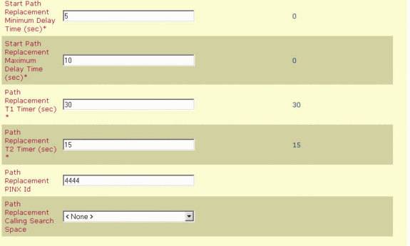
Under Service parameters, make sure that the Start Path Replacement Minimum and Maximum time values are set appropriately in order to prevent any issues (such as hair pinning).
The next two screen captures relate to the Q.SIG Service Parameters settings:
-
Add Cisco 3745 as an MGCP gateway and configure the NM-HDV T-1 module for the Q.SIG PRI.
The next five screen captures relate to this configuration:


-
As a final step, create a Cisco Call Manager pickup group in order to provide a path proposal extension to the PBX. Make sure that the call pickup number is also entered into the Path PINX Replacement ID Service parameter (see to step# 1). Also, the Avaya system needs a route pattern in order to route to the pickup group.

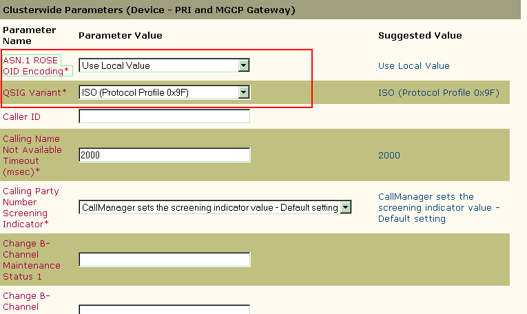
Note: Make sure that these two clusterwide parameters (Device - PRI and MGCP Gateway) under Cisco CallManager Service Parameters (Advanced) match the Q.SIG configuration in the PBX. All PBX trunks must be configured exactly as these Cisco CallManager parameters.
-
ASN.1 ROSE OID Encoding: This parameter specifies how to encode the Invoke Object ID (OID) for the Remote Operations Service Element (ROSE). Keep this parameter set to the default value unless a Cisco support engineer instructs otherwise. These is a required field and the default is Use Local Value.
These are the valid values for this parameter:
-
Use Local Value, which is supported by most telephony systems and must be used when the Q.SIG Variant service parameter is set to ISO (Protocol Profile 0x9F).
-
Use Global Value (ISO), which is used only if the connected PBX does not support Use Local Value.
-
Use Global Value (ECMA), which must be used if the Q.SIG Variant service parameter is set to ECMA (Protocol Profile 0x91).
-
-
Q.SIG Variant: This parameter specifies the protocol profile sent in outbound Q.SIG facility information elements when the trunk is configured for Q.SIG. Keep this parameter set to the default value unless a Cisco support engineer instructs otherwise. This is a required field, and the default is ISO (Protocol Profile 0x9F).
These are the available values for this parameter:
-
ECMA (Protocol Profile 0x91), which is typically used with ECMA PBXs and can only use Protocol Profile 0x91. If this service parameter is set to ECMA (Protocol Profile 0x91), the ASN.1 Rose OID Encoding service parameter must be set to Use Global Value (ECMA).
-
ISO (Protocol Profile 0x9F), which is the current ISO recommendation. If this parameter is set to ISO (Protocol Profile 0x9F), then the ASN.1 Rose OID Encoding service parameter must be set to Use Local Value.
Warning: Cisco CallManager does not support ECMA when using intercluster trunks with the Tunneled Protocol field set to Q.SIG in the Trunk Configuration window in the CallManager Administration. If you set this service parameter to ECMA (Protocol Profile 0x91), all intercluster trunks must have the Tunneled Protocol field set to None.
-
-
Cisco 3745 Configuration
This is the show version and show running-configuration command output on the Cisco 3745 MGCP device. Controller T1 1/0 on the Cisco 3745 is connected to the Avaya S8700/G650 DS1 PRI card. Q.SIG signaling is configured on PRI link between the Cisco 3745 and the Avaya S8700/G650.
CCME_CUE_3745# sh vers
Cisco Internetwork Operating System Software
IOS (tm) 3700 Software (C3745-IS-M), Version 12.2(15)ZJ3, EARLY DEPLOYMENT RELEASE SOFTWARE (fc2)
TAC Support: http://www.cisco.com/tac
Copyright (c) 1986-2003 by cisco Systems, Inc.
Compiled Thu 25-Sep-03 22:25 by eaarmas
Image text-base: 0x60008954, data-base: 0x61C2C000

ROM: System Bootstrap, Version 12.2(8r)T2, RELEASE SOFTWARE (fc1)
ROM: 3700 Software (C3745-IS-M), Version 12.2(15)ZJ3, EARLY DEPLOYMENT RELEASE SOFTWARE (fc2)

CCME_CUE_3745 uptime is 39 minutes
System returned to ROM by reload
System image file is "flash:c3745-is-mz.122-15.ZJ3.bin"

cisco 3745 (R7000) processor (revision 2.0) with 246784K/15360K bytes of memory.
Processor board ID JMX0814L3E2
R7000 CPU at 350Mhz, Implementation 39, Rev 3.3, 256KB L2, 2048KB L3 Cache
Bridging software.
X.25 software, Version 3.0.0.
SuperLAT software (copyright 1990 by Meridian Technology Corp).
Primary Rate ISDN software, Version 1.1.
2 FastEthernet/IEEE 802.3 interface(s)
25 Serial network interface(s)
1 terminal line(s)
2 Channelized T1/PRI port(s)
1 ATM AIM(s)
2 Voice FXS interface(s)
2 Voice E & M interface(s)
1 cisco service engine(s)
DRAM configuration is 64 bits wide with parity disabled.
151K bytes of non-volatile configuration memory.
125184K bytes of ATA System CompactFlash (Read/Write)
Configuration register is 0x2102

CCME_CUE_3745# sh run
Building configuration...

Current configuration : 3291 bytes
!
version 12.2
service timestamps debug datetime msec
service timestamps log datetime msec
no service password-encryption
!
hostname CCME_CUE_3745
!
logging queue-limit 100
!
voice-card 1
 dspfarm
!
voice-card 5
 dspfarm
!
ip subnet-zero
!
!
no ip domain lookup
!
isdn switch-type primary-qsig
!
no voice hpi capture buffer
no voice hpi capture destination
!
!
ccm-manager mgcp
ccm-manager music-on-hold
ccm-manager config server 172.28.221.18
ccm-manager config
mta receive maximum-recipients 0
!
!
controller T1 1/0
 framing esf
 linecode b8zs
 pri-group timeslots 1-24 service mgcp
!
controller T1 1/1
 framing sf
 linecode ami
!
!
!
interface FastEthernet0/0
 description CCME-CUE-3745_to_cat3550
 no ip address
 duplex auto
 speed auto
!
interface FastEthernet0/0.1
 encapsulation dot1Q 99
!
interface FastEthernet0/0.2
 description NEW_S8700_G650
 encapsulation dot1Q 300
 ip address 172.28.221.49 255.255.255.240
 ip helper-address 172.28.221.19
 h323-gateway voip bind srcaddr 172.28.221.49
!
interface FastEthernet0/0.3
 description MODULAR_MESSAGING_SOLUTION
 encapsulation dot1Q 900
 ip address 172.28.221.129 255.255.255.240
 ip helper-address 172.28.221.19
!
interface FastEthernet0/0.4
 encapsulation dot1Q 301
 ip address 10.1.3.1 255.255.255.128
 ip helper-address 172.28.221.19
!
interface FastEthernet0/0.5
 encapsulation dot1Q 302
 ip address 10.1.3.129 255.255.255.128
 ip helper-address 172.28.221.19
!
interface FastEthernet0/0.6
 encapsulation dot1Q 90
 ip address 90.1.1.254 255.255.255.0
 ip helper-address 172.28.221.19
!
interface Serial0/0
 description CCME-CUE-3745_to_3600
 ip address 25.0.0.1 255.0.0.0
 clockrate 256000
 no fair-queue
!
interface Serial1/0:23
 no ip address
 no logging event link-status
 isdn switch-type primary-qsig
 isdn incoming-voice voice
 isdn bind-l3 ccm-manager
 isdn bchan-number-order ascending
 no cdp enable
!
interface Service-Engine2/0
 no ip address
 shutdown
!
router eigrp 100
 network 10.0.0.0
 network 25.0.0.0
 network 90.0.0.0
 network 172.28.0.0
 auto-summary
!
ip http server
ip classless
!
call rsvp-sync
!
voice-port 1/0:23
!
voice-port 4/0/0
!
voice-port 4/0/1
!
voice-port 4/1/0
!
voice-port 4/1/1
!
mgcp
mgcp call-agent 172.28.221.18 2427 service-type mgcp version 0.1
mgcp dtmf-relay voip codec all mode out-of-band
mgcp rtp unreachable timeout 1000 action notify
mgcp package-capability rtp-package
no mgcp package-capability res-package
mgcp package-capability sst-package
no mgcp timer receive-rtcp
mgcp sdp simple
mgcp fax t38 inhibit
mgcp rtp payload-type g726r16 static
!
mgcp profile default
!
!
!
dial-peer cor custom
!
dial-peer voice 1 pots
 application mgcpapp
 port 1/0:23
!
dial-peer voice 999410 pots
 application mgcpapp
 port 4/1/0
!
!
line con 0
 password cisco
 login
line 65
 flush-at-activation
 no activation-character
 no exec
 transport preferred none
 transport input all
line aux 0
line vty 0 4
 password cisco
 login
!
end
Features Tested for Interoperability between Cisco and Avaya IP-PBX Systems
This section provides a list of features tested between the Cisco Call Manager 4.1(2) platform and the Avaya S8700/G650 running Communication Manager 2.0 by way of the Q.SIG PRI trunk:
-
Name and Number Display (bi-directional)
-
Call Transfer
-
Conference Call between the two systems
Integration of Cisco Unity Voice Mail to Support Cisco and Avaya IP Phones
At this point, one can use the Q.SIG trunk in order to make calls between an Avaya S8700/G650 running Avaya Communication Manager 2.0 and a Cisco Call Manager platform running Call Manager version 4.1(2) with the Cisco 3745 MGCP device providing the physical ISDN PRI connection to the Avaya S8700/G650. A Cisco Unity server can be added on the Cisco Call Manager platform in order to provide voice mail support to both the Cisco and Avaya IP phones. In order to enable this, the administrator needs to configure the Cisco Unity on the Cisco Call Manager platform. This section includes the procedures with screen captures for how to configure Cisco Unity on the Cisco Call Manager Administration management page.
Note: Most of the configuration is performed on the Cisco Voice Mail Port Wizard.
Add Cisco Unity to Cisco Call Manager
Complete these steps:
-
Under Feature, select Voice Mail > Voice Mail Port Wizard. Select Create a new voice mail server and add ports to it and click Next.

-
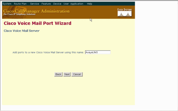
Enter a Cisco Voice Mail Server name, such as AvayaUM3, and click Next.
-
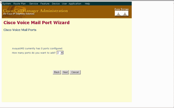
Select the number of Voice Mail Ports desired and click Next.
-
Enter a Description and Device Pool for the Voice Mail Ports. In the sample configuration, Avaya VMailPorts was entered as the description and Default as the device pool.

-
Enter the Beginning Directory Number, such as 4406, and the Display, such as Voice Mail, and click Next.

-
The next screen asks, "Do you want to add these directory numbers to a Line Group?" Select Yes. Add directory numbers to a new Line Group and click Next.

-
Enter a Line Group Name which matches the Voice Mail Server you previously entered, such as AvayaUM3.

-
The next screen shows the configuration entered so far. Click Finish if there are no changes to the configuration.

-
Click Add a New Hunt List on the Hunt List Administration web page.

-
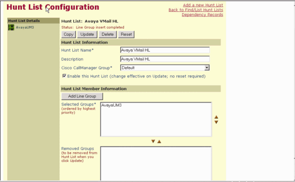
Enter a Hunt List Name and Description, such as Avaya VMailHL. Also, select Default for the Cisco Call Manager Group.

-
This screen capture is the result of the successful addition of the Hunt List. Click Add Line Group.

-
Select the Line Group previously configured. In this case, it is AvayaUM3.

-
The next screen capture shows the result of the successful insertion of the line group.
-
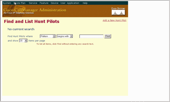
Go to Route Plan > Route/Hunt > Hunt Pilot. Click Add a New Hunt Pilot from the Hunt Pilot screen that results.
-
Enter in the Hunt Pilot, such as 4408, and select a Hunt List, such as Avaya VMail HL and click Insert.

-
Go to Feature > Voice Mail > Voice Mail Pilot and click Add a New Voice Mail Pilot on the screen that results.

-
Enter the Voice Mail Pilot number matching the Hunt Pilot number previously configured. In this case, both the Hunt Pilot and Voice Mail Pilot numbers are 4408.

-
Go to Feature > Voice Mail > Voice Mail Profile and click Add a New Voice Mail Profile.

-
Enter the Voice Mail Profile Name and Description, such as AvayaVMailProfile, and select the Voice Mail Pilot number in step 17. In this case, the Voice Mail Pilot number is 4408.

-
Click Features > Voice Mail > Message Waiting Indicator > Add a New Message Waiting Number to add the Message Waiting Indicator (MWI) On/Off numbers. Included here are two screen captures for Message Waiting Indicator On/Off numbers.


Cisco Unity Voice Mail Features Tested
This is a list of Cisco Unity Voice Mail features tested with the Avaya IP phones used to access Cisco Unity Voice Mail by way of the Q.SIG PRI trunk between the Cisco Call Manager 4.1(2) platform and the Avaya S8700/G650 running Communication Manager 2.0:
-
Internal greeting
-
Busy greeting
-
MWI
-
Easy message access
Related Information
Contact Cisco
- Open a Support Case

- (Requires a Cisco Service Contract)


 Feedback