E1 Layer 1 Troubleshooting
Available Languages
Contents
Introduction
This document describes the techniques and procedures to troubleshoot E1 Layer 1 problems. If E1 problems persist after you complete the procedures in this document, refer to E1 Error Events Troubleshooting and E1 Alarm Troubleshooting in order to isolate and correct your problem.
Prerequisites
Requirements
There are no specific requirements for this document.
Components Used
This document is not restricted to specific software and hardware versions.
The information in this document was created from the devices in a specific lab environment. All of the devices used in this document started with a cleared (default) configuration. If your network is live, make sure that you understand the potential impact of any command.
Conventions
Refer to Cisco Technical Tips Conventions for more information on document conventions.
Troubleshooting with the show controller e1 Command
The show controller e1 command displays the controller status specific to the controller hardware. This information is useful for diagnostic tasks performed by technical support personnel. The Network Processor Module (NPM) or MultiChannel Interface Processor (MIP) can query the port adapters to determine their current status.
The show controller e1 EXEC command also provides:
-
Statistics about the E1 link. If you specify a slot and a port number, statistics for each 15 minute period are displayed.
-
Information to troubleshoot physical layer and data link layer problems.
-
Local or remote alarm information, if any, on the E1 line.
Most E1 errors are caused by incorrectly configured lines. Ensure that line coding, framing, and clock source are configured in accordance to the recommendations of your Service Provider.
The E1 controller can be in three states:
-
Administratively down
-
Down
-
Up
Refer to Understanding the show controllers e1 Command for more information on how to read the show controller e1 command output.
Administratively Down E1 Controller
The controller is administratively down when it has been manually shut down. Complete these steps to restart the controller to correct this error:
-
Enter enable mode.
For example:
bru-nas-03>en
Password:
bru-nas-03#
-
Enter global configuration mode.
For example:
bru-nas-03#configure terminal
Enter configuration commands, one per line. End with CNTL/Z.
bru-nas-03(config)#
-
Enter controller configuration mode.
For example:
bru-nas-03(config)#controller e1 0
bru-nas-03(config-controlle)#
-
Restart the controller.
bru-nas-03(config-controlle)#no shutdown
Ensuring the Line is Up
If the E1 controller and line are not up, make sure one of these messages appears in the show controller e1 EXEC output:
Receiver has loss of frame.
or
Receiver has loss of signal.
Loss of Frame
Complete these steps if the receiver has loss of frame:
-
Ensure the framing format configured on the port matches the framing format of the line.
-
Check the framing format of the controller from the running configuration or the show controller e1 command output.
-
Issue the framing {crc4 | no-crc4} command in controller configuration mode in order to change the framing format.
For example:
bru-nas-03#configure terminal
Enter configuration commands, one per line. End with CNTL/Z.
bru-nas-03(config)#controller e1 0
bru-nas-03(config-controlle)#framing crc4
-
-
Try the other framing format to see if the alarm clears.
If this does not fix the problem, see the Loss of Signal section.
Loss of Signal
Complete these steps if the receiver has loss of signal:
-
Ensure the cable between the interface port and the E1 Service Provider equipment or E1 terminal equipment is connected correctly.
-
Ensure the cable is hooked up to the correct ports.
-
Correct the cable connections if necessary.
-
-
Check the cable integrity by looking for breaks or other physical abnormalities in the cable.
-
Ensure the pinouts are set correctly.
-
Replace the cable if necessary.
-
-
Check the cable connectors.
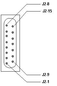
A reversal of the transmit and receive pairs or an open receive pair can cause errors. The cable terminates on a male DB-15 or RJ-45/48 connector, which depends on the type of module used. On a DB-15 connector, the receive pair should be on pins 2 and 9, and the transmit pair on pins 8 and 15.
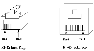
The pins on an RJ-45/48 cable are numbered from 1 through 8. With the metal pins facing toward you, and the cable hanging down, pin 1 is the left-most pin. This is a figure that shows the pin numbering on an RJ-45 jack and plug:

In an RJ-45/48 jack, the receive pair should be on lines 1 and 2, and the transmit pair should be on lines 4 and 5.
The pins on an RJ-45/48 jack plug are numbered from 1 through 8. With the metal pins facing toward you, pin 1 is the left-most pin. This is a figure that shows the pin numbering on an RJ-45 jack:

-
If you have completed all of these steps and you still experience problems, use a rollover cable.
Issue the show controller e1 EXEC command after each step in order to see if the controller exhibits any errors.
Loopback Mode
Ensure the line is in loopback mode from the show controller e1 command output. The line should be in loopback mode only for testing purposes.
Issue the no loopback command in controller configuration mode in order to turn off loopback. For example:
bru-nas-03(config-controlle)#no loopback
Refer to Hard Plug Loopback Tests for E1 Lines for information on how to perform a hard plug loopback test to verify that the E1 controller and card operate correctly.
If these steps do not solve the E1 problem, refer to E1 Error Events Troubleshooting, E1 Alarm Troubleshooting, and E1 PRI Troubleshooting.
Related Information
Revision History
| Revision | Publish Date | Comments |
|---|---|---|
1.0 |
02-Jan-2007 |
Initial Release |
Contact Cisco
- Open a Support Case

- (Requires a Cisco Service Contract)


 Feedback