Bridge Security
Available Languages
Contents
Introduction
Security is a vital consideration when designing a bridged wireless link between Ethernet segments. This document demonstrates how to secure the traffic crossing a bridged wireless link by the use of an IPSEC tunnel.
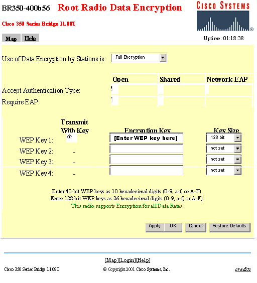
In this example, two Cisco Aironet 350 Series Bridges establish WEP; the two routers set up an IPSEC tunnel.
Prerequisites
Requirements
Before attempting this configuration, ensure that you are comfortable with the use of these:
-
Cisco Aironet Bridge configuration interface
-
Cisco IOS command line interface
Components Used
The information in this document is based on these software and hardware versions:
-
Cisco 2600 Series routers running IOS version 12.1
-
Cisco Aironet 350 Series Bridges running firmware version 11.08T
The information presented in this document was created from devices in a specific lab environment. All of the devices used in this document started with a cleared (default) configuration. If you are working in a live network, ensure that you understand the potential impact of any command before using it.
Background Theory
Cisco Aironet 340, 350, and 1400 Series Bridges provide up to 128-bit WEP encryption. This cannot be relied upon for secure connectivity due to well-known problems in WEP algorithms and the ease of exploitation, as described in Security of the WEP algorithm ![]() and in the Cisco Aironet Response to Press - Flaws in 802.11 Security.
and in the Cisco Aironet Response to Press - Flaws in 802.11 Security.
One method of increasing the security of traffic passed across a wireless bridged link is to create an encrypted router-to-router IPSEC tunnel that crosses the link. This works because bridges operate at layer 2 of the OSI model. You can run IPSEC router-to-router over the connection between the bridges.
If the security of the wireless link is breached, the traffic it contains remains encrypted and secure.
Conventions
For more information on document conventions, see the Cisco Technical Tips Conventions.
Configure
This section presents information to configure the features described in this document.
Note: To find additional information on the commands used in this document, use the IOS Command Lookup tool.
Network Diagram
This document uses the network setup shown in this diagram:

Configurations
This document uses these configurations:
| RouterA (Cisco 2600 Router) |
|---|
RouterA#show running-config Building configuration... Current configuration : 1258 bytes ! version 12.1 no service single-slot-reload-enable no service pad service timestamps debug uptime service timestamps log uptime no service password-encryption ! hostname RouterA ! logging rate-limit console 10 except errors ! ip subnet-zero no ip finger ip dhcp excluded-address 10.1.1.20 ip dhcp excluded-address 10.1.1.30 ! ip dhcp pool wireless network 10.1.1.0 255.255.255.0 ! ip audit notify log ip audit po max-events 100 call rsvp-sync ! crypto isakmp policy 10 hash md5 authentication pre-share crypto isakmp key cisco address 10.1.1.30 ! ! crypto ipsec transform-set set esp-3des esp-md5-hmac ! crypto map vpn 10 ipsec-isakmp set peer 10.1.1.30 set transform-set set match address 120 ! interface Loopback0 ip address 20.1.1.1 255.255.255.0 ! interface Ethernet0 ip address 10.1.1.20 255.255.255.0 crypto map vpn ! ! ip classless ip route 0.0.0.0 0.0.0.0 10.1.1.30 no ip http server no ip http cable-monitor ! access-list 120 permit ip 20.1.1.0 0.0.0.255 30.1.1.0 0.0.0.255 ! ! line con 0 transport input none line vty 0 4 ! end |
| RouterB (Cisco 2600 Router) |
|---|
RouterB#show running-config Building configuration... Current configuration : 1177 bytes ! version 12.1 no service single-slot-reload-enable no service pad service timestamps debug uptime service timestamps log uptime no service password-encryption ! hostname RouterB ! logging rate-limit console 10 except errors ! ip subnet-zero no ip finger ! ip audit notify log ip audit po max-events 100 call rsvp-sync crypto isakmp policy 10 hash md5 authentication pre-share crypto isakmp key cisco address 10.1.1.20 ! ! crypto ipsec transform-set set esp-3des esp-md5-hmac ! crypto map vpn 10 ipsec-isakmp set peer 10.1.1.20 set transform-set set match address 120 interface Loopback0 ip address 30.1.1.1 255.255.255.0 ! interface Ethernet0 ip address 10.1.1.30 255.255.255.0 no ip mroute-cache crypto map vpn ! ip classless ip route 0.0.0.0 0.0.0.0 10.1.1.20 no ip http server no ip http cable-monitor ! access-list 120 permit ip 30.1.1.0 0.0.0.255 20.1.1.0 0.0.0.255 ! ! line con 0 transport input none line vty 0 4 login ! end |
| Cisco Aironet Bridges |
|---|
| |
Verify
This section provides information you can use to confirm your configuration is working properly.
Certain show commands are supported by the Output Interpreter Tool (registered customers only) , which allows you to view an analysis of show command output.
-
show crypto engine connections active - this command is used to view the current active encrypted session connections
RouterA#show crypto engine connection active
  ID Interface   IP-Address      State Algorithm             Encrypt Decrypt
   1 Ethernet0   10.1.1.20       set   HMAC_MD5+DES_56_CB          0      0
2002 Ethernet0   10.1.1.20       set   HMAC_MD5+3DES_56_C          0      3
2003 Ethernet0   10.1.1.20       set   HMAC_MD5+3DES_56_C          3      0

RouterB#show crypto engine connection active
  ID Interface    IP-Address     State Algorithm             Encrypt Decrypt
   1  <none>         <none>      set   HMAC_MD5+DES_56_CB          0      0
2000 Ethernet0    10.1.1.30      set   HMAC_MD5+3DES_56_C          0      3
2001 Ethernet0    10.1.1.30      set   HMAC_MD5+3DES_56_C          3      0
Troubleshoot
This section provides information you can use to troubleshoot your configuration.
To troubleshoot IPSEC connectivity, refer to:
-
IP Security Troubleshooting—Understanding and Using debug Commands
-
Configuring and Troubleshooting Cisco Network-Layer Encryption: IPSec and ISAKMP, Part 1 and Part 2
For troubleshooting the wireless connection, refer to:
Related Information
Revision History
| Revision | Publish Date | Comments |
|---|---|---|
1.0 |
10-May-2006 |
Initial Release |
Contact Cisco
- Open a Support Case

- (Requires a Cisco Service Contract)

 Feedback