H-REAP Modes of Operation Configuration Example
Available Languages
Contents
Introduction
This document introduces the concept of Hybrid Remote Edge Access Point (H-REAP) and explains its different modes of operation with an example configuration.
Prerequisites
Requirements
Ensure that you meet these requirements before you attempt this configuration:
-
Knowledge of Wireless LAN Controllers (WLCs) and how to configure the WLC basic parameters
-
Knowledge of REAP
Components Used
The information in this document is based on these software and hardware versions:
-
Cisco 4400 Series WLC that runs firmware release 7.0.116.0
-
Cisco 1131AG Lightweight Access Point (LAP)
-
Cisco 2800 Series Routers that run version 12.4(11)T.
-
Cisco Aironet 802.11a/b/g Client Adapter that runs firmware release 4.0
-
Cisco Aironet Desktop Utility version 4.0
-
Cisco Secure ACS that runs version 4.0
The information in this document was created from the devices in a specific lab environment. All of the devices used in this document started with a cleared (default) configuration. If your network is live, make sure that you understand the potential impact of any command.
Conventions
Refer to Cisco Technical Tips Conventions for more information on document conventions.
Background Information
H-REAP is a wireless solution for branch office and remote office deployments. H-REAP enables customers to configure and control access points (APs) in a branch or remote office from the corporate office through a WAN link without deploying a controller in each office.
H-REAPs can switch client data traffic locally and perform client authentication locally when the connection to the controller is lost. When connected to the controller, H-REAPs can also tunnel traffic back to the controller. In connected mode, the hybrid REAP AP can also perform local authentication.
H-REAP is supported only on:
-
1130AG, 1140, 1240, 1250, 1260, AP801, AP 802, 1040, and AP3550 APs
-
Cisco 5500, 4400, 2100, 2500, and Flex 7500 Series Controllers
-
Catalyst 3750G Integrated Controller Switch
-
Catalyst 6500 Series Wireless Services Module (WiSM)
-
Wireless LAN Controller Module (WLCM) for Integrated Services Routers (ISRs)
Client traffic on H-REAPs can either be switched locally at the AP or tunneled back to a controller. This depends on per-WLAN configuration. Also, locally switched client traffic on the H-REAP can be 802.1Q tagged to provide for wired-side separation. During WAN outage, service on all locally switched, locally authenticated WLANs persists.
Note: If the APs are in H-REAP mode and locally switched at the remote site, the dynamic assignment of users to a specific VLAN based on the RADIUS server configuration is not supported. However, you should be able to assign users to specific VLANs based on the static VLAN to service set identifier (SSID) mapping done locally at the AP. Therefore, a user that belongs to a particular SSID can be assigned to a specific VLAN to which the SSID is mapped locally at the AP.
Note: If voice over WLAN is important, then the APs should be run in local mode so that they get CCKM and Connection Admission Control (CAC) support, which are not supported in H-REAP mode.
H-REAP over REAP
Refer to Remote-Edge AP (REAP) with Lightweight APs and Wireless LAN Controllers (WLCs) Configuration Example for more information to help understand REAP.
H-REAP was introduced as a result of these shortcomings of REAP:
-
REAP does not have wired-side separation. This is due to lack of 802.1Q support. Data from the WLANs land on the same wired subnet.
-
During a WAN failure, a REAP AP ceases service offered on all WLANs, except the first one specified in the controller.
This is how H-REAP overcomes these two shortcomings:
-
Provides dot1Q support and VLAN to SSID mapping. This VLAN to SSID mapping needs to be done at H-REAP. While you perform this, ensure that configured VLANs are properly allowed through the ports in intermediate switches and routers.
-
Provides continuous service to all WLANs configured for local switching.
Configure
In this section, you are presented with the information to configure the features described in this document.
Network Diagram
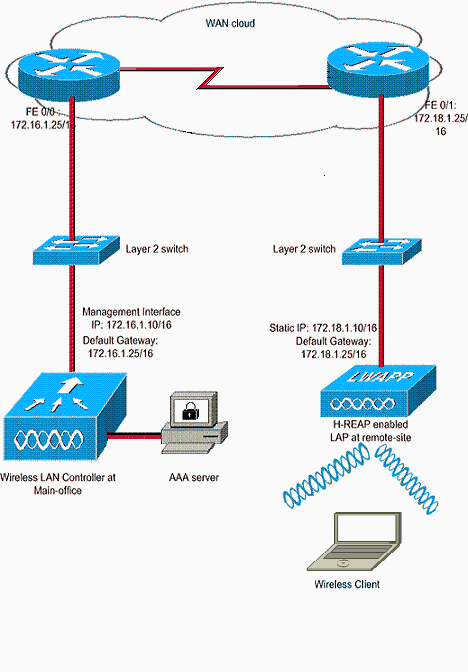
This document uses this network setup:
Configuration
This example assumes that the controller is already configured with basic configurations. The controller uses these configurations:
-
Management interface IP address—172.16.1.10/16
-
AP-Manager interface IP address—172.16.1.11/16
-
Default Gateway router IP address—172.16.1.25/16
-
Virtual Gateway IP address—1.1.1.1
Note: This document does not show WAN configurations and configuration of routers and switches available between the H-REAP and the controller. This assumes that you are aware of the WAN encapsulation and the routing protocols that are used. Also, this document assumes that you understand how to configure them in order to maintain connectivity between the H-REAP and controller through the WAN link. In this example, HDLC encapsulation is used on the WAN link.
Priming the AP with a Controller and Configure H-REAP
If you want the AP to discover a controller from a remote network where CAPWAP discovery mechanisms are not available, you can use priming. This method enables you to specify the controller to which the AP should connect.
In order to prime an H-REAP-capable AP, connect the AP to the wired network at the main office. During its boot up, the H-REAP-capable AP first looks for an IP address for itself. Once it acquires an IP address through a DHCP server, it boots up and looks for a controller to perform the registration process.
An H-REAP AP can learn the controller IP address in any of the ways explained in Lightweight AP (LAP) Registration to a Wireless LAN Controller (WLC).
Note: You can also configure the LAP to discover the controller through CLI commands at the AP. Refer to H-REAP Controller Discovery using CLI commands for more information.
The example in this document uses the DHCP option 43 procedure for the H-REAP to learn the controller IP address. Then it joins the controller, downloads the latest software image and configuration from the controller, and initializes the radio link. It saves the downloaded configuration in non-volatile memory for use in standalone mode.
Once the LAP is registered with the controller, complete these steps:
-
In the Controller GUI, choose Wireless>Access Points.
This displays the LAP registered with this controller.
-
Click on the AP that you want to configure.

-
In the APs>Details window, click on the High Availability tab, and define the controller names that the APs will use to register, then click Apply.
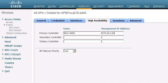
You can define up to three controller names (primary, secondary, and tertiary). The APs search for the controller in the same order that you provide in this window. Because this example uses only one controller, the example defines the controller as the primary controller.
-
Configure LAP for H-REAP.
In order to configure the LAP to operate in H-REAP mode, in the APs>Details window, under the General tab, choose AP mode as H-REAP from the corresponding drop down menu.
This configures the LAP to operate in H-REAP mode.
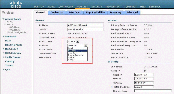
Note: In this example, you can see that the IP address of the AP is changed to static mode and the static IP address 172.18.1.10 has been assigned. This assignment occurs because this is the subnet to be used at the remote office. Therefore, you use the IP address from the DHCP server, but only during the first time through the registration stage. After the AP is registered to the controller, you change the address to a static IP address.
Now that your LAP is primed with the controller and configured for H-REAP mode, the next step is to configure H-REAP at the controller side and discuss the H-REAP switching states.
H-REAP Theory of Operations
The H-REAP-capable LAP operates in these two different modes:
-
Connected mode:
An H-REAP is said to be in connected mode when its CAPWAP control plane link to the WLC is up and operational. This means that the WAN link between the LAP and WLC is not down.
-
Standalone mode:
An H-REAP is said to be in the standalone mode when its WAN link to the WLC is down. For example, when this H-REAP no longer has connectivity to the WLC connected across the WAN link.
The authentication mechanism used to authenticate a client can be defined as Central or Local.
-
Central Authentication—Refers to the authentication type that involves the process of the WLC from the remote site.
-
Local Authentication—Refers to the authentication types that do not involve any processing from the WLC for authentication.
Note: All 802.11 authentication and association processing occurs at the H-REAP, no matter which mode the LAP is in. While in connected mode, H-REAP then proxies these associations and authentications to the WLC. In standalone mode, the LAP cannot inform the WLC of such events.
When a client connects to an H-REAP AP, the AP forwards all authentication messages to the controller. After successful authentication, its data packets are then either switched locally or tunneled back to the controller. This is in accordance to the configuration of the WLAN to which it is connected.
With H-REAP, the WLANs configured on a controller can be operated in two different modes:
-
Central Switching:
A WLAN on H-REAP is said to operate in central switching mode if the data traffic of that WLAN is configured to be tunneled to the WLC.
-
Local Switching:
A WLAN on H-REAP is said to operate in local switching mode if the data traffic of that WLAN terminates locally at the wired interface of the LAP itself, without getting tunneled to the WLC.
Note: Only WLANs 1 through 8 can be configured for H-REAP Local Switching because only these WLANs can be applied to the 1130, 1240 and 1250 Series APs that support H-REAP functionality.
H-REAP Switching States
Combined with the authentication and switching modes mentioned in the previous section, an H-REAP can operate in any of these states:
Central Authentication, Central Switching
In this state, for the given WLAN, the AP forwards all client authentication requests to the controller and tunnels all client data to the WLC. This state is valid only when the H-REAP is in the connected mode. Any WLAN that is configured to operate in this mode is lost during WAN outage, no matter what the authentication method is.
This example uses these configuration settings:
-
WLAN/SSID name: Central
-
Layer 2 Security: WPA2
-
H-REAP Local Switching: disabled
Complete these steps in order to configure the WLC for central authentication, central switching using GUI:
-
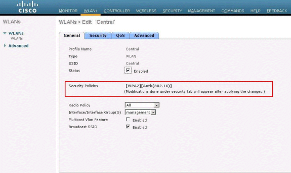
Click WLANs in order to create a new WLAN named Central, then click Apply.

-
Because this WLAN uses central authentication, we use WPA2 authentication in the Layer 2 Security field. WPA2 is the default Layer 2 Security for a WLAN.
-
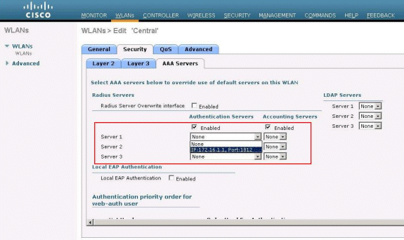
Choose the AAA Servers tab, and then choose the appropriate server configured for authentication.
-
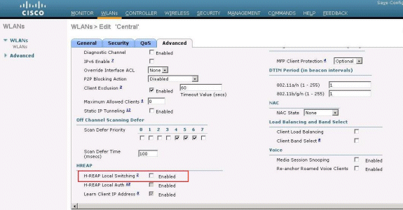
Because this WLAN uses central switching, you need to ensure that the H-REAP Local Switching check box is disabled (i.e. Local Switching check box is not selected). Then, click Apply.
Verify Central Authentication, Central Switching
Complete these steps:
-
Configure the wireless client with the same SSID and security configurations.
In this example, the SSID is Central and the security method is WPA2.
-
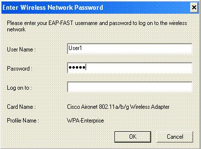
Enter the username and password as configured in the RADIUS server>User Setup in order to activate the central SSID in the client.
This example uses User1 as the username and password.
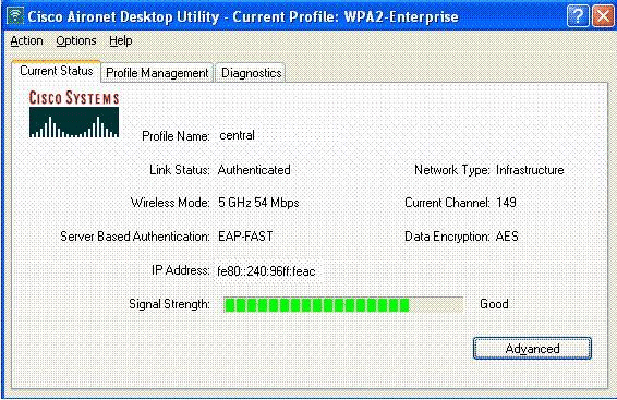
The client is centrally authenticated by the RADIUS server and is associated with the H-REAP AP. The H-REAP is now in central authentication, central switching.
Authentication Down, Switching Down
With the same configuration explained in the Central Authentication, Central Switching section, disable the WAN link that connects the controller. Now, the controller waits for a heartbeat reply from the AP. A heartbeat reply is similar to keepalive messages. The controller tries five consecutive heartbeats, each every one second.
Because it is not received with a heartbeat reply from the H-REAP, the WLC deregisters the LAP.
Issue the debug capwap events enable command from the WLC's CLI in order to verify the deregistration process. This is the example output of this debug command:
Thu Jan 18 03:19:32 2007: 00:15:c7:ab:55:90 Did not receive heartbeat reply from
AP 00:15:c7:ab:55:90
Thu Jan 18 03:19:32 2007: 00:15:c7:ab:55:90 apfSpamProcessStateChangeInSpamConte
xt: Down capwap event for AP 00:15:c7:ab:55:90 slot 0
Thu Jan 18 03:19:32 2007: 00:15:c7:ab:55:90 apfSpamProcessStateChangeInSpamConte
xt: Deregister capwap event for AP 00:15:c7:ab:55:90 slot 0
Thu Jan 18 03:19:32 2007: 00:15:c7:ab:55:90 apfSpamProcessStateChangeInSpamConte
xt: Down capwap event for AP 00:15:c7:ab:55:90 slot 1
Thu Jan 18 03:19:32 2007: 00:15:c7:ab:55:90 apfSpamProcessStateChangeInSpamConte
xt: Deregister capwap event for AP 00:15:c7:ab:55:90 slot 1
Thu Jan 18 03:19:32 2007: 00:15:c7:ab:55:90 Received capwap Down event for AP 00:
15:c7:ab:55:90 slot 0!
Thu Jan 18 03:19:32 2007: 00:15:c7:ab:55:90 Deregister capwap event for AP 00:15:
c7:ab:55:90 slot 0
Thu Jan 18 03:19:32 2007: 00:15:c7:ab:55:90 Received capwap Down event for AP 00:
15:c7:ab:55:90 slot 1!
Thu Jan 18 03:19:32 2007: 00:15:c7:ab:55:90 Deregister capwap event for AP 00:15:
c7:ab:55:90 slot 1
The H-REAP goes into standalone mode.
Because this WLAN was previously centrally authenticated and centrally switched, both control and data traffic were tunneled back to the controller. Therefore, without the controller, the client is unable to maintain association with the H-REAP and it is disconnected. This state of H-REAP with both client association and authentication being down is referred to as Authentication Down, Switching Down.
Central Authentication, Local Switching
In this state, for the given WLAN, the WLC handles all client authentication, and the H-REAP LAP switches data packets locally. After the client authenticates successfully, the controller sends capwap control commands to the H-REAP and instructs the LAP to switch that given client’s data packets locally. This message is sent per client upon successful authentication. This state is applicable only in connected mode.
This example uses these configuration settings:
-
WLAN/SSID name: Central-Local
-
Layer 2 Security: WPA2.
-
H-REAP Local Switching: Enabled
From the Controller GUI, complete these steps:
-
Click WLANs in order to create a new WLAN named Central-Local, then click Apply.
-
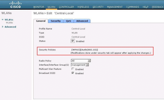
Because this WLAN uses central authentication, choose WPA2 authentication in the Layer 2 Security field.
-
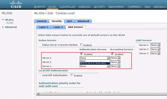
Under the Radius Servers section, choose the appropriate server configured for authentication.
-
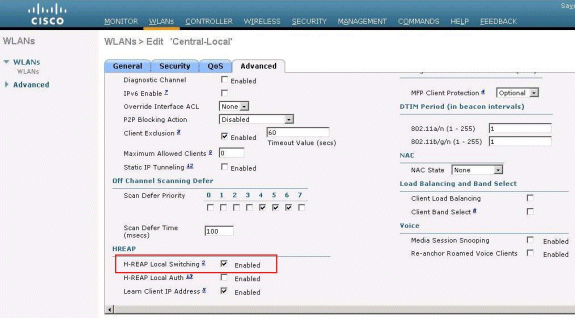
Check the H-REAP Local Switching check box in order to switch client traffic that belongs to this WLAN locally at the H-REAP.
Verify Central Authentication, Local Switching
Complete these steps:
-
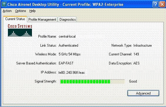
Configure the wireless client with the same SSID and security configurations.
In this example, the SSID is Central-Local and the security method is WPA2.
-
Enter the username and password as configured in the RADIUS server>User Setup in order to activate the central-local SSID in the client.
This example uses User1 as the username and password.

-
Click OK.
The client is centrally authenticated by the RADIUS server and gets associated with the H-REAP AP. The H-REAP is now in central authentication, local switching.
Authentication Down, Local Switching
If a locally switched WLAN is configured for any authentication type that is required to be processed on the WLC (such as EAP authentication [dynamic WEP/WPA/WPA2/802.11i], WebAuth, or NAC), upon WAN failure, it enters the authentication down, local switching state. In this state, for the given WLAN, the H-REAP rejects any new clients that try to authenticate. However, it continues to send beacons and probe responses to keep existing clients properly connected. This state is valid only in standalone mode.
In order to verify this state, use the same configuration explained in the Central Authentication, Local Switching section.
If the WAN link that connects the WLC is down, the WLC goes through the process of deregistering the H-REAP.
Once deregistered, H-REAP goes into standalone mode.
The client associated through this WLAN still maintains its connectivity. However, because the controller, the authenticator is not available, H-REAP does not allow any new connections from this WLAN.
This can be verified by the activation of another wireless client in the same WLAN. You can find that the authentication for this client fails and that client is not allowed to associate.
Note: When a WLAN client count equals zero, the H-REAP ceases all associated 802.11 functions and no longer beacons for the given SSID. This moves the WLAN to the next H-REAP state, authentication down, switching down.
Local Authentication, Local Switching
In this state, the H-REAP LAP handles client authentications and switches client data packets locally. This state is valid only in standalone mode and only for authentication types that can be handled locally at the AP and do not involve the processing of controller
The H-REAP that was previously in the central authentication, local switching state, moves into this state, provided the configured authentication type can be handled locally at the AP. If the configured authentication cannot be handled locally, such as 802.1x authentication, then in standalone mode, the H-REAP goes to authentication down, local switching mode.
These are some of the popular authentication mechanisms that can be handled locally at the AP in standalone mode:
-
Open
-
Shared
-
WPA-PSK
-
WPA2-PSK
Note: All authentication processes are handled by the WLC when the AP is in the connected mode. While the H-REAP is in standalone mode, open, shared, and WPA/WPA2-PSK authentications are transferred to the LAPs where all client authentication occurs.
Note: External Web authentication is not supported when using hybrid-REAP with local switching enabled on the WLAN.
This example uses these configuration settings:
-
WLAN/SSID name: Local
-
Layer 2 Security: WPA-PSK
-
H-REAP Local Switching: enabled
From the Controller GUI, complete these steps:
-
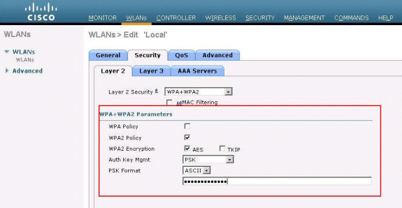
Click WLANs in order to create a new WLAN named Local, then click Apply.
-
Because this WLAN uses local authentication, choose WPA-PSK or any of the mentioned security mechanisms that can be handled locally in the Layer 2 Security field.
This example uses WPA-PSK.
-
Once chosen, you need to configure the Pre-shared Key/Pass Phrase to be used.
This must be the same at the client side for authentication to be successful.
-
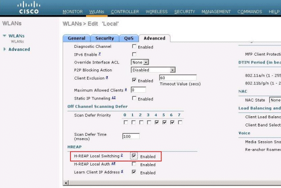
Check the H-REAP Local Switching check box in order to switch client traffic that belongs to this WLAN locally at the H-REAP.
Verify Local Authentication, Local Switching
Complete these steps:
-
Configure the client with the same SSID and security configurations.
Here, the SSID is Local and the security method is WPA-PSK.
-
Activate the Local SSID in the client.
The client gets authenticated centrally at the controller and associates with the H-REAP. The client traffic is configured to switch locally. Now, the H-REAP is in Central Authentication, Local Switching state.
-
Disable the WAN link that connects to the controller.
The controller as usual goes through the deregistration process. H-REAP is deregistered from the controller.
Once deregistered, H-REAP goes into standalone mode.
However, the client that belongs to this WLAN still maintains association with H-REAP.
Also, because the authentication type here can be handled locally at the AP without the controller, H-REAP does allow associations from any new wireless client through this WLAN.
-
In order to verify this, activate any other wireless client on the same WLAN.
You can see that the client is authenticated and associated successfully.
Troubleshoot
-
In order to further troubleshoot client connectivity issues at the H-REAP's console port, enter this command:
AP_CLI#show capwap reap association
-
In order to further troubleshoot client connectivity issues at the controller and to limit the output of further debugging, use this command:
AP_CLI#debug mac addr <client’s MAC address> -
In order to debug a client's 802.11 connectivity issues, use this command:
AP_CLI#debug dot11 state enable
-
Debug a client's 802.1X authentication process and failures with this command:
AP_CLI#debug dot1x events enable
-
Backend controller/RADIUS messages may be debugged using this command:
AP_CLI#debug aaa events enable
-
Alternatively, to enable a complete suit of client debug commands, use this command:
AP_CLI#debug client <client’s MAC address>
Related Information
- Wireless LAN Controller and Lightweight Access Point Basic Configuration Example
- VLANs on Wireless LAN Controllers Configuration Example
- Cisco Wireless LAN Controller Configuration Guide, Release 7.0
- Hybrid REAP Design and Deployment Guide
- Hybrid Remote Edge Access Point (H-REAP) Basic Troubleshooting
- WLAN Controller Failover for Lightweight Access Points Configuration Example
- Wireless Product Support
- Technical Support & Documentation - Cisco Systems
Revision History
| Revision | Publish Date | Comments |
|---|---|---|
1.0 |
18-Jan-2007 |
Initial Release |
Contact Cisco
- Open a Support Case

- (Requires a Cisco Service Contract)


 Feedback