Basic Radar Survey for Wireless Mesh Networks
Available Languages
Contents
Introduction
This document offers two methods to scan for radar signals across 802.11a outdoor channels before deployment of mesh networks. One based on 4.0.217.200 image, the other using newer functionality on the mesh released, in particular 4.1.192.17M. It covers both 1520 and 1510 mesh access point families.
The objective is to provide a mechanism to check for possible radar signals that can affect a wireless mesh network that uses 802.11a as backhaul links.
It is important to validate the presence of radar on any wireless mesh deployment. If during operation, an access point (AP) detects a radar event over the Radio Frequency (RF) channel that the network backhaul uses, it must immediately change to another available RF channel. This is dictated by Federal Communications Commission (FCC) and European Telecommunications Standards Institute (ETSI) standards, and is established to allow the sharing of the 5 GHz spectrum between wireless LAN (WLAN) and military or weather radars that use the same frequencies.
The effects of radar signal over a wireless mesh network with 802.11a backhaul can be different. This depends on where the radar is detected and on the state of “full sector DFS mode” configuration setting (in case it is disabled):
-
If a mesh access point (MAP) sees the radar on the current channel, it goes silent for one minute [dynamic frequency selection (DFS) timer]. Then, the MAP starts to scan channels for a suitable new parent to associate again to the mesh network. The previous channel is marked as not usable for 30 minutes. If the parent [other MAP or rooftop access point (RAP)] does not detect the radar, it remains on the channel and is not visible for the MAP that did detect it. This situation can occur if the detecting MAP is closer or in line of sight of the radar, and the other APs are not. If no other parent is available in another channel (no redundancy), the MAP remains off network for the 30 minutes of the DFS timer.
-
If a RAP sees the radar event, it goes silent for one minute, and then selects a new channel from the 802.11a Auto RF channel list (if currently joined to controller). This causes this section of the mesh network to go down, as RAP has to change channel, and all the MAPs have to search for new parent location.
In case that full sector DFS is enabled:
-
If a MAP sees the radar on the current channel, it notifies RAP of the radar detection. The RAP then triggers a full sector channel change (RAP plus all its dependant MAPs). All devices after going into the new channel, go silent for one minute, to detect for possible radio signals on the new channel. After this time, they resume normal operation.
-
If a RAP sees the radar event, it notifies all MAPs for a channel change. All devices after going into the new channel, go silent for one minute, to detect for possible radio signals on the new channel. After this time, they resume normal operation.
The feature of “full sector DFS mode” is available on mesh releases 4.0.217.200 and later. The main impact is that the full sector will go one minute on silent mode after channel change (mandated by DFS), but it has the advantages that it prevents MAPs to become isolated if they detect radar, but its parent not.
It is advisable that before you plan and install, contact the local authorities in order to obtain information if there is any known radar installation nearby, such as weather, military, or an airport. Also, in harbors, it is possible that passing or incoming ships might have radar that affects the mesh network, which might not be present during the survey phase.
In case that severe radar interference is detected, it is still possible to build the network using 1505 APs. This is instead of using 802.11a radio as backhaul. The 1505 APs can use 802.11g, sharing it with the client access. This represents a technical alternative for sites too close to a powerful radar source.
On most situations, removing the affected channels can suffice to have a operable network. The total number of channels affected depends on radar type, and distance from the deployment site to the radar source, line of sight, etc.
Note: If the method proposed in this document is used, it does not make any warranties that there is not radar in the tested area. It constitutes a initial test to prevent possible issues after deployment. Due to the normal variations on RF conditions for any outdoor deployment, it is possible that the detection probability can change.
Prerequisites
Requirements
Cisco recommends that you have knowledge of these topics:
-
Knowledge of how to configure wireless LAN controllers (WLCs) and lightweight access points (LAPs) for basic operation
-
Knowledge of Lightweight Access Point Protocol (LWAPP) and wireless security methods
-
Basic knowledge of wireless mesh networks: how they are configured and operate
Components Used
The information in this document is based on these software and hardware versions:
-
Cisco 2100 / 4400 Series WLC that runs firmware 4.1.192.17M or newer, or 4.0.217.200
-
LWAPP-based Access Points, series 1510 or 1520
-
Cognio Spectrum Expert 3.1.67
The information in this document was created from the devices in a specific lab environment. All of the devices used in this document started with a cleared (default) configuration. If your network is live, make sure that you understand the potential impact of any command.
Conventions
Refer to Cisco Technical Tips Conventions for more information on document conventions.
Basic Radar Survey
Additional Information
Refer to Dynamic Frequency Selection and IEEE 802.11h Transmit Power Control for information on DFS.
Starting Points
-
Upgrade your WLC to version 4.1.192.17M or later. Check documentation for details.
-
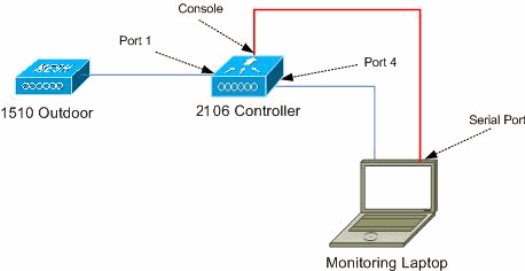
The controller used in this example is a 2106 in order to make it easier for portability on the field. Other controller types can be used.
-
For simplicity reasons, this guide starts from a empty configuration, and assumes that the controller is a stand alone device, which serves the DHCP address to the AP.
Topology
This diagram shows the topology for the features described in this document:
Selecting a Good Location for the Survey
-
It is important to think of the radar energy as a light source. Anything that can be on the path to the survey tool, from the radar source, can generate a shadow or completely hide the radar energy. Buildings, trees, etc can cause signal attenuation.
-
Doing the capture indoors is not a substitution for a proper outdoor survey. For example, a glass window can produce 15 dBm of attenuation to a radar source.
-
No matter what kind of detection is used, it is important to select a location that has the least obstructions around, preferably near where the final APs will be located, and if possible at the same height.
Selecting the Detecting Equipment
Each device will detect radar depending on its radio characteristics. It is important to use the same device type that will be used for the mesh deployments (1522, 1510, etc).
Initial Setup
The CLI startup wizard is used in order to configure initial settings on controller. In particular, the controller has:
-
802.11b network disabled
-
No RADIUS servers, as the controller does not offer normal wireless services
-
WLAN 1 created as the script needs it, but it will be deleted later.
Upon boot up of the WLC, you see this output:
Launching BootLoader...

 Cisco Bootloader (Version 4.0.191.0)


                      .o88b. d888888b .d8888.  .o88b.  .d88b.

                     d8P  Y8   `88'   88'  YP d8P  Y8 .8P  Y8.

                     8P         88    `8bo.   8P      88    88

                     8b         88      `Y8b. 8b      88    88

                     Y8b  d8   .88.   db   8D Y8b  d8 `8b  d8'

                      `Y88P' Y888888P `8888Y'  `Y88P'  `Y88P'


Booting Primary Image...
Press <ESC> now for additional boot options...
Detecting hardware . . . .

Cisco is a trademark of Cisco Systems, Inc.
Software Copyright Cisco Systems, Inc. All rights reserved.


Cisco AireOS Version 4.1.192.17M (Mesh)
Initializing OS Services: ok
Initializing Serial Services: ok
Initializing Network Services: ok
Starting ARP Services: ok
Starting Trap Manager: ok
Starting Network Interface Management Services: ok
Starting System Services: ok

Starting Fast Path Hardware Acceleration: ok
Starting Switching Services: ok
Starting QoS Services: ok

Starting FIPS Features: Not enabled
Starting Policy Manager: ok
Starting Data Transport Link Layer: ok
Starting Access Control List Services: ok
Starting System Interfaces: ok
Starting Client Troubleshooting Service: ok
Starting Management Frame Protection: ok
Starting LWAPP: ok
Starting Crypto Accelerator: Not Present
Starting Certificate Database: ok
Starting VPN Services: ok
Starting Security Services: ok
Starting Policy Manager: ok
Starting Authentication Engine: ok
Starting Mobility Management: ok
Starting Virtual AP Services: ok
Starting AireWave Director: ok
Starting Network Time Services: ok
Starting Cisco Discovery Protocol: ok
Starting Broadcast Services: ok
Starting Power Over Ethernet Services: ok
Starting Logging Services: ok
Starting DHCP Server: ok
Starting IDS Signature Manager: ok
Starting RFID Tag Tracking: ok
Starting Mesh Services: ok
Starting TSM: ok
Starting LOCP: ok
Starting CIDS Services: ok
Starting Ethernet-over-IP: ok
Starting Management Services:
   Web Server: ok
   CLI: ok
   Secure Web: Web Authentication Certificate not found (error).


(Cisco Controller)

Welcome to the Cisco Wizard Configuration Tool
Use the '-' character to backup
System Name [Cisco_24:13:a0]:
Enter Administrative User Name (24 characters max): admin
Enter Administrative Password (24 characters max): *****
Re-enter Administrative Password                 : *****
Management Interface IP Address: 192.168.100.1
Management Interface Netmask: 255.255.255.0
Management Interface Default Router: 192.168.100.254
Management Interface VLAN Identifier (0 = untagged): 0
Management Interface Port Num [1 to 8]: 1
Management Interface DHCP Server IP Address: 192.168.100.1
AP Manager Interface IP Address: 192.168.100.2
AP-Manager is on Management subnet, using same values
AP Manager Interface DHCP Server (192.168.100.1):
Virtual Gateway IP Address: 1.1.1.1
Mobility/RF Group Name: 2106
Enable Symmetric Mobility Tunneling [yes][NO]:
Network Name (SSID): 2106
Allow Static IP Addresses [YES][no]:
Configure a RADIUS Server now? [YES][no]: no
Warning! The default WLAN security policy requires a RADIUS server.
Please see documentation for more details.
Enter Country Code list (enter 'help' for a list of countries) [US]: BE

Enable 802.11b Network [YES][no]: no
Enable 802.11a Network [YES][no]: yes
Enable Auto-RF [YES][no]:

Configuration saved!

Resetting system with new configuration...
-
Log into the controller after boot with the username and password combination used from this output:
...
Starting Management Services:
   Web Server: ok
   CLI: ok
   Secure Web: ok

(Cisco Controller)

Enter User Name (or 'Recover-Config' this one-time only to reset configuration to
factory defaults)

User: admin
Password:*****
(Cisco Controller) >
-
In order to limit the complexity of the setup, the controller has a special configuration to limit services offered. Also, the WLC is set up as the DHCP server for the AP:
config wlan delete 1
config dhcp create-scope dfs
config dhcp network dfs 192.168.100.0 255.255.255.0
config dhcp address-pool dfs 192.168.100.100 192.168.100.120
config dhcp enable dfs
-
As the 1500 AP is added to the controller, you should know the MAC address, so it can be authorized. The information can be gathered from the sticker on the AP, or by using the debug lwapp errors enable command on the controller in case the AP is already installed. As the AP is not yet authorized, it is possible to easily see the MAC address:
Cisco Controller) >debug lwapp errors enable

(Cisco Controller) >Tue Apr 24 04:27:25 2007: spamRadiusProcessResponse:
AP Authorization failure for 00:1a:a2:ff:8f:00
-
Use the found address to add to the controller:
config auth-list add mic 00:1a:a2:ff:8f:00
-
After a short time, both APs should join the controller. Write down the AP names, as these will be used along the test.
The name will be different on your setup. This depends on the AP MAC address, if it was configured before, etc. For the example of this document, the name of the AP is ap1500.
(Cisco Controller) >show ap summary

AP Name             Slots  AP Model             Ethernet MAC       Location          Port
------------------  -----  -------------------  -----------------  ----------------  ----
ap1500               2     LAP1500              00:1a:a2:ff:8f:00  default_location  3

(Cisco Controller) >
Radar Tests using 4.1.192.17M
The radar test consists of these steps:
-
Enable radar debugs on controller. Use the debug airewave-director radar enabled command.
-
Disable the radio of the AP with the config 802.11a disable <APNAME> command.
-
Select a channel, then manually set the 802.11a radio on it. Cisco recommends starting from the highest channel (140), and then decreasing toward 100. Weather radar tends to be on higher channel area. Use the config 802.11a channel <APNAME> <CHANNELNUM> command.
-
Enable the 802.11a radio of the AP with the config 802.11a enable <APNAME> command.
-
Wait until the radar debug is generated, or a “safe” time, for example 30 minutes in order to make sure there is no fixed radar on that channel.
-
Repeat for the next channel on the outdoor list for your country, for example: 100, 104,108, 112, 116, 120, 124, 128, 132, 136, 140.
This is an example of a radar detection on channel 124:
(Cisco Controller) >config 802.11a channel ap AP1520-RAP 124

Tue Apr  1 15:50:16 2008: Airewave Director: Checking Phy Chan Options on 802.11a AP
00:1A:A2:FF:8F:00(1)  chan 112 (DO-SCAN,COMMIT, (4704,112))
Tue Apr  1 15:50:16 2008: Airewave Director: Verify New Chan (124) on AP
Tue Apr  1 15:50:16 2008: Airewave Director: radar check is not required or not detected on
channel (124) on AP
Tue Apr  1 15:50:16 2008: Airewave Director: Checking radar Data on 802.11a AP
00:1A:A2:FF:8F:00(1)
Tue Apr  1 15:50:16 2008: Airewave Director: active channel 112 customized channel 0
for 802.11a
Tue Apr  1 15:50:16 2008: Airewave Director: Radar non-occupancy expired on 802.11a AP
00:1A:A2:FF:8F:00(1)  chan 120
Tue Apr  1 15:50:16 2008: Airewave Director: Checking Phy Chan Options on 802.11a AP
00:1A:A2:FF:8F:00(1)  chan 124 (DO-SCAN,COMMIT, (4704,112))
Tue Apr  1 15:50:18 2008: Airewave Director: Processing radar data on 802.11a AP
00:1A:A2:FF:8F:00(1)
Tue Apr  1 15:50:18 2008: Airewave Director: Updating radar data on 802.11a AP
00:1A:A2:FF:8F:00(1)  chan 124
Tue Apr  1 15:50:18 2008: Airewave Director: Checking radar Data on 802.11a AP
00:1A:A2:FF:8F:00(1)
Tue Apr  1 15:50:18 2008: Airewave Director: active channel 124 customized channel 0
for 802.11a
Tue Apr  1 15:50:18 2008: Airewave Director: Radar detected on 802.11a AP
00:1A:A2:FF:8F:00(1)  chan 124
Tue Apr  1 15:50:18 2008: Succeeded Sending RadarChannel Trap
Tue Apr  1 15:50:18 2008: Airewave Director: Avoiding Radar: changing to channel 108
for 802.11a
Radar Tests using 4.0.217.200
This method can be used for controllers running older mesh code (4.0.217.200), which only supports mesh APs model 1510.
The radar test consists of these steps:
-
In order to reduce the information displayed, the controller is configured to only show traps for AP related events:
config trapflags authentication disable
config trapflags linkmode disable
config trapflags multiusers disable
config trapflags 802.11-Security wepDecryptError disable
config trapflags rrm-profile load disable
config trapflags rrm-profile coverage disable
config trapflags aaa auth disable
config trapflags aaa servers disable
-
Enable debug for trap events:
debug snmp trap enable
-
Disable the radio of the AP with the config 802.11a disable <APNAME> command.
-
Select a channel, then manually set the 802.11a radio on it. Cisco recommends to start from the highest channel (140), then decrease toward 100. Weather radar tends to be on higher channel area. Use the config 802.11a channel <APNAME> <CHANNELNUM> command.
-
Enable the 802.11a radio of the AP with the config 802.11a enable <APNAME> command.
-
Wait until the radar trap is generated, or a “safe” time, for example 30 minutes in order to make sure there is no radar on that channel.
-
Repeat for the next channel on the outdoor list for your country, for example: 100, 104,108, 112, 116, 120, 124, 128, 132, 136, 140.
This is an example of testing one channel:
    (Cisco Controller) >config 802.11a disable ap1500

    !Controller notifies of radio interface going down
    Tue Apr 24 22:26:23 2007: Succeeded Sending lradIfTrap
    (Cisco Controller) >


    !Channel is set on AP radio
    (Cisco Controller) >config 802.11a channel ap1500 132
     Set 802.11a channel to 132 on AP ap1500.
    (Cisco Controller) >


    !Radio interface is enabled
    (Cisco Controller) >config 802.11a enable ap1500
    Tue Apr 24 22:30:05 2007: Succeeded Sending lradIfTrap
    (Cisco Controller) >
After a few minutes, the radar is detected and notification is sent.
Tue Apr 24 22:31:43 2007: Succeeded Sending RadarChannel Trap
Immediately, the channel is changed and a new one is selected by the AP.
Tue Apr 24 22:31:43 2007: Succeeded Sending bsnLradIfParam Update Trap
-
In order to verify the new channel selected after the DFS event, issue the show advanced 802.11a summary command:
(Cisco Controller) >show advanced 802.11a summary

             AP Name                          Channel     TxPower Level

             -------------------------------- ----------- -------------

             ap1500                              108            1

(Cisco Controller) >
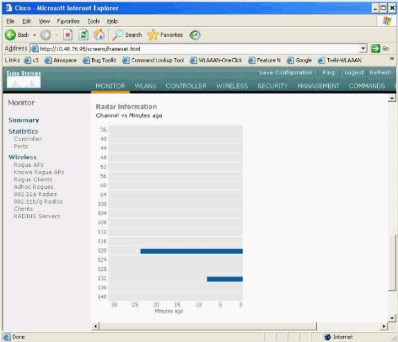
The AP keeps the information on what channels have seen radar for 30 minutes, as required by regulation. This information can be seen from the GUI interface on the controller in Monitor > 802.11a Radios page.
-
Select the AP used for channel testing and scroll down to the bottom of the frame:
Radar Events Count in AP
Use a remote command from the controller in order to obtain the count of radar events detected directly from the AP. This shows the total number of events since the AP was reloaded:
(Cisco Controller) >debug ap enable ap1500
(Cisco Controller) >debug ap command printRadar() ap1500
(Cisco Controller) >Tue Apr 24 23:07:24 2007: ap1500: Calling "printRadar" with args 0x0, 0x0, 0x0, 0x0
Tue Apr 24 23:07:24 2007: ap1500: Radar detection algorithm parameters
Tue Apr 24 23:07:24 2007: ap1500:     max width =  25 (units of 0.8 us),
width matching pulses minimum = 5
Tue Apr 24 23:07:24 2007: ap1500:     width margin = +/- 5
Tue Apr 24 23:07:24 2007: ap1500:     min rssi for magnitude detection = 75
Tue Apr 24 23:07:24 2007: ap1500:     min pulses for magnitude detection = 2
Tue Apr 24 23:07:24 2007: ap1500:     maximum non-matching pulses to discard sample = 2
Tue Apr 24 23:07:24 2007: ap1500: Radar detection statistics
Tue Apr 24 23:07:24 2007: ap1500:     samples dropped for too many errors per second = 0
Tue Apr 24 23:07:24 2007: ap1500:     samples dropped for too many errors in sample = 0
Tue Apr 24 23:07:24 2007: ap1500:     positive radar bursts detected = 14
Tue Apr 24 23:07:24 2007: ap1500: printRadar Returns: 40
Tue Apr 24 23:07:24 2007: ap1500:
(Cisco Controller) >debug ap disable ap1500
Radar Affected Channels in AP 1520
Use a remote command from the controller in order to obtain the list of radar affected channels directly from the AP.
(Cisco Controller) >debug ap enable AP1520-RAP
(Cisco Controller) >debug ap command "sh mesh channel" AP1520-RAP
(Cisco Controller) >Tue Apr  1 15:38:19 2008: AP1520-RAP:
Tue Apr  1 15:38:19 2008: AP1520-RAP: ===========================================
Tue Apr  1 15:38:19 2008: AP1520-RAP:  HW: GigabitEthernet2, Channels:
Tue Apr  1 15:38:19 2008: AP1520-RAP:  2[0;0],
Tue Apr  1 15:38:19 2008: AP1520-RAP: ===========================================
Tue Apr  1 15:38:19 2008: AP1520-RAP:  HW: GigabitEthernet3, Channels:
Tue Apr  1 15:38:19 2008: AP1520-RAP:  3[0;0],
Tue Apr  1 15:38:19 2008: AP1520-RAP: ===========================================
Tue Apr  1 15:38:19 2008: AP1520-RAP:  HW: GigabitEthernet0, Channels:
Tue Apr  1 15:38:19 2008: AP1520-RAP:  0[0;0],
Tue Apr  1 15:38:19 2008: AP1520-RAP: ===========================================
Tue Apr  1 15:38:19 2008: AP1520-RAP:  HW: GigabitEthernet1, Channels:
Tue Apr  1 15:38:19 2008: AP1520-RAP:  1[0;0],
Tue Apr  1 15:38:19 2008: AP1520-RAP: ===========================================
Tue Apr  1 15:38:19 2008: AP1520-RAP:  HW: Dot11Radio1, Channels:
Tue Apr  1 15:38:19 2008: AP1520-RAP:  100[0;0], 104[0;0], 108[0;0], 112[0;0], 116[0;0],
120*[0;0], 124*[0;0], 128[0;0], 132[0;0], 136[0;0], 140[0;0],
All channels with a “*” symbol next to it indicate a channel marked as radar present. These channels will remain blocked for 30 minutes.
Using Cognio Spectrum Analyzer
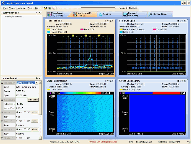
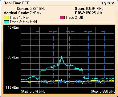
For additional details on the radar signals found by the WLC debug commands described earlier, use the Cognio Spectrum Analyzer in order to validate. Due to the signal characteristics, the software does not generate an alert on the signal itself. However, if you use the Real Time FTT “max hold” trace, you can obtain a picture and verify the number of detected channels.
It is important to take into consideration that the antenna gain, the sensitivity of the 1510 AP's 802.11a radio, and the Cognio sensor are different. Therefore, it is possible that the reported signal levels differ between what the Cognio tool and the 1510 AP report.
If the radar signal level is too low, it is possible that it is not detected by the Cognio sensor because of lower antenna gain.
Make sure that no other 802.11a devices are active that can affect the capture; for example, the Wi-Fi card in the laptop used during the test.
In order to perform the capture, go to the Cognio Spectrum Expert, and set these parameters:
-
Use the external antenna.
-
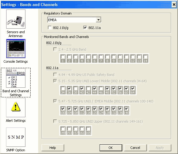
In Tools, go to Settings. Choose Band and Channel Settings, then select your regulatory domain, and only check the 802.11a box. Then, click OK.
-
Click the Real Time FFT plot in order to select it.
-
In the Control Panel, verify that the Trace 3 is On, and set to Max Hold.
-
In the same section, verify that the Frequency is set to Center Freq/Span, and the band is 5.47 – 5.726 Ghz Band.
After enough capture time, the max hold trace shows the radar signal characteristics:
-
Use the start/stop settings available in the Control Panel in order to zoom into the signal plot.
This allows you to get more details on the total channels affected and power of the signal:
Steps to Take if a Radar is Detected
It is possible to customize the default 802.11a channel list. Therefore, when a RAP is connected to the controller, and it is necessary to do a dynamic channel selection, the previously known affected channels are not used.
In order to implement this, it is only necessary to change the Auto RF channel selection list, which is a global parameter to the controller. The command to use is config advanced 802.11a channel delete <CHANNELNUM>. For example:
(Cisco Controller) >config advanced 802.11a channel delete 124
(Cisco Controller) >config advanced 802.11a channel delete 128
(Cisco Controller) >config advanced 802.11a channel delete 132
In order to verify the current list of channels, issue the show advanced 802.11a channel command:
(Cisco Controller) >show advanced 802.11a channel

Automatic Channel Assignment
  Channel Assignment Mode........................ AUTO
  Channel Update Interval........................ 600 seconds
  Channel Update Contribution.................... SNI.
  Channel Assignment Leader...................... 00:18:ba:94:64:c0
  Last Run....................................... 331 seconds ago
  Channel Energy Levels
    Minimum...................................... unknown
    Average...................................... unknown
    Maximum...................................... unknown
  Channel Dwell Times
    Minimum...................................... 0 days, 17 h 49 m 30 s
    Average...................................... 0 days, 18 h 49 m 20 s
    Maximum...................................... 0 days, 19 h 49 m 10 s
  Allowed Channel List........................... 36,40,44,48,52,56,60,64,100,
    ............................................. 104,108,112,116,120,136,140
Related Information
Revision History
| Revision | Publish Date | Comments |
|---|---|---|
1.0 |
01-Dec-2013 |
Initial Release |
Contact Cisco
- Open a Support Case

- (Requires a Cisco Service Contract)


 Feedback