Video Surveillance over Mesh Deployment Guide
Available Languages
Contents
Introduction
This document discusses the deployment of Video Surveillance over Cisco Mesh access points. It introduces the Cisco Mesh architecture and then discusses video surveillance deployment issues.
Key Takeaways
Some of the Key Takeaways are
-
Cisco Mesh Network supports Video Surveillance.
-
Cisco Aironet 1524SB ideal for Video Surveillance across Wireless Mesh Network.
-
18 Mbits can be achieved in an ideal environment 12Mbits can be achieved in a Challenging environment
Background Information
The Cisco Aironet 1520 Series Lightweight Outdoor Mesh Access Points are a high-performance outdoor wireless mesh product family for a cost-effective, scalable, and secure deployment in outdoor environments such as corporate or educational campuses, municipalities and other public safety environments, and oil and gas refineries, mining operations, or other outdoor enterprises. The Cisco Aironet 1520 Series delivers design innovation for radio versatility and provides flexibility in the deployment of wireless mesh networks in dynamic environments. The Cisco Aironet 1520 Series Lightweight Outdoor Mesh access points is also a part of the Cisco Unified Wireless Network.
Deployment Guidelines
Key Features and Benefits of the Platform
These are the features and benefits of the platform:
-
Versatile—Provides a platform that enables mobility regardless of the frequency band required
-
Extensible—Enables the broadband wireless infrastructure to easily and securely extend services to third-party devices, such as IP cameras and automated meter readers, deployed in the harshest environmental conditions.
-
Fortified—Provides the highest standard of security with a secure rugged enclosure and the Cisco Self-Defending Network architecture.
-
The 1520 Series wireless broadband platform operates with Cisco WLAN controllers and Cisco Wireless Control System (WCS) software, centralizing key functions of WLANs to provide scalable management, configuration, and security and transparent mobility between indoor and outdoor environments.
-
18 Mbits can be achieved in an ideal environment; 12Mbits can be achieved in a Challenging environment.
Cisco Aironet 1520 Series Consists of the 1522 Dual-radio Mesh Access Point and the 1524 Multi-radio Mesh Access Point
The Cisco Aironet 1520 supports dual-band radios compliant with IEEE 802.11a and 802.11b/g standards. Various uplink connectivity options such as Gigabit Ethernet (1000BaseT), and small form-factor pluggable (SFP) for fiber (100BaseBX) or cable modem interface are supported. Support power options include 480VAC, 12VDC, cable power, Power over Ethernet (POE), and internal battery backup. It also employs Cisco's Adaptive Wireless Path Protocol (AWPP) to form a dynamic wireless mesh network between remote access points, while delivering secure, high-capacity wireless access to any Wi-Fi-compliant client device.
The dual-radio configuration of the Cisco Aironet 1520 lightweight outdoor mesh access point dedicates the 802.11a radio to access-point-to-access-point communications, allows the mesh network to maximize all available channels, minimize the occurrence of interference from unlicensed devices, and minimize latency. The dual-radio configuration delivers high system capacity and performance through pico-cell designs.
Key Features on the Cisco Aironet 1520
These are the key features:
-
Dual-radio support (802.11a, 802.11b/g)
-
Improved 802.11b/g radio sensitivity and range performance on the three-channel Maximal Ratio Combining (MRC).
-
Multiple uplink options (Gigabit Ethernet-1000BaseT, Fiber-100BaseBX, and cable modem interface).
-
NEMA 4X certified enclosure, certification for hazardous locations (Class 1, Division 2 / Zone 2. Group B, C, D-United States/Canada/EU), (optional).
-
FIPS 140-2 certifiable
-
LED status indicators
The Cisco Aironet 1524 is pre-configured with three radios compliant with IEEE 802.11a, 802.11b/g and 4.9GHz public safety standards. Various uplink connectivity options such as Gigabit Ethernet (10/100/1000BaseT), and small form-factor pluggable (SFP) for fiber interface are supported. Support power options include 480VAC, 12VDC, Power over Ethernet (POE), and internal battery backup. It also employs Cisco's Adaptive Wireless Path Protocol (AWPP) to form a dynamic wireless mesh network between remote access points, and delivers secure, high-capacity wireless access to any Wi-Fi-compliant client device. The modular design of the Cisco Aironet 1524 Lightweight Outdoor Mesh Access Point creates a flexible platform that can enable separate mesh access networks within the device. With multiple separate radios dedicated to access, the Cisco Aironet 1524 creates the most robust and secure mesh infrastructure able to support public and private applications simultaneously.
Key Features of the Cisco Aironet 1524
-
Modular radio support (802.11a, 802.11b/g, licensed 4.9GHz public safety)
-
Upgradeable to new radio technologies
-
Improved 802.11g radio sensitivity and range performance with Maximal Ratio Combining (MRC)
-
Multiple uplink options (Gigabit Ethernet-10/100/1000BaseT, Fiber SFP interface)
-
Multiple power options (Power over Ethernet, 480 VAC Streetlight Power, 12 VDC, and internal battery backup power)
-
802.3af-compliant Power over Ethernet interface to connect IP devices
-
NEMA 4X certified enclosure
-
LED status indicators
Mesh Architecture and Video Deployment Guidelines
Configuration and Deployment Guide
This document describes how to configure Mesh access points in an Outdoor environment to support Video Surveillance applications. This document builds on concepts introduced in the 1520 series deployment guide and provides deployment and configuration considerations for Video Surveillance.
Pre-requisites
Ensure that the following requirements are met before you attempt to configure.
-
Familiarity with basic wireless mesh technology
-
Working mesh network
-
Basic understanding of how Cameras work. The cameras can be Analog cameras using encoders & decoders, wired & Wireless IP cameras
Please refer to the Cisco Mesh AP 1520 series deployment guide for a more fundamental good understanding of Cisco Mesh access point installation considerations.
This document provides design and deployment guidelines for the deployment of secure enterprise, campus and metropolitan Wi-Fi network within the Cisco mesh networking solution.
Solution Components
The information in this document is based on these software and hardware versions:
-
Cisco WLC5500/4400 that runs firmware 6.0.182.0
-
Cisco 152x Series Lightweight Mesh Access points with Omni directional antennas.
-
Analog Cameras, IP wired Cameras, Wireless IP cameras.
-
Encoders/decoders or Transmitter/Recorder.
-
Video monitoring software/server
-
Coax Cables /breakout boxes, accessories for Cameras.
Cisco 4400 Series Wireless LAN Controller
Wireless LAN controllers simplify the deployment and operation of wireless networks and help to ensure smooth performance, enhanced security, and maximum network availability. Cisco wireless LAN controllers communicate with Cisco Aironet access points over any Layer 2 or Layer 3 infrastructure to support system wide wireless LAN (WLAN) functions such as:
-
Enhanced security with WLAN policy monitoring and intrusion detection
-
Intelligent radio frequency (RF) management
-
Centralized management
-
Quality of service (QOS)
-
Mobility services such as guest access, voice over Wi-Fi and location services
Cisco wireless LAN controllers support 802.11a/b/g and the IEEE 802.11n standard, so you can deploy the solution that meets your individual requirements. From voice and data services to location tracking, Cisco wireless LAN controller products provide the control, scalability, security, and reliability you need to build highly secure, enterprise-scale wireless networks.
Refer to Wireless LAN Controllers for more information about various controllers and their capabilities.
Cisco 152x Series Lightweight Mesh Access Point
The Cisco Aironet 1520 Series mesh access point is a high-performance outdoor wireless mesh product for a cost-effective, scalable, and secure deployment in outdoor environments such as municipalities, public safety environments, and oil and gas or other outdoor enterprises. The Cisco Aironet 1520 Series delivers design innovation for radio versatility and provides flexibility in the deployment of wireless mesh networks in dynamic environments. Key features and benefits of the platform are:
-
Versatile—Provides a platform that enables mobility regardless of the frequency band required with universal slots that allow for rapid development and integration of radio technology
-
Extensible—Enables the broadband wireless infrastructure to easily and securely extend services to third-party devices, such as IP cameras and automated meter readers, in the harshest environmental conditions
-
Fortified—Provides the highest standard of security with a secure rugged enclosure and the Cisco Self-Defending Network architecture
-
The 1520 Series wireless broadband platform operates with Cisco WLAN controllers and Cisco Wireless Control System (WCS) software and centralizes key functions of WLANs to provide scalable management, configuration, and security and transparent mobility between indoor and outdoor environments.
Refer to Outdoor Wireless Network Solution for more information about the access points and their capabilities.
Cisco 152x Antennas
Every wireless LAN deployment is different. A proper Antenna must be identified based on the requirements and the environment in which the wireless is deployed.
Cisco has a wide range of 2.4 as well as 5 GHz Antennas to meet different requirements. The Antennas come with N-type connectors that are fully compatible with 1520 Access points.
The Cisco antennas are available with different gain and range capabilities, beam widths, and form factors. When you couple the appropriate antenna and access point, it allows for efficient coverage in any facility, as well as better reliability at higher data rates. Refer to Cisco Aironet Antennas and Accessories Reference Guide for more information about the Antennas and supported access points.
Topology Overview
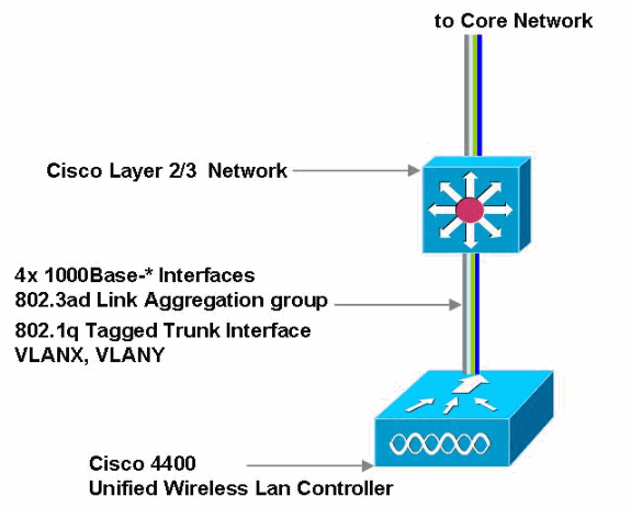
This section illustrates the steps to build a mesh network from scratch. In the image, a Layer 3 and Layer 2 network are established and connectivity between the controller and switch is tested with a login to the controller from an Ethernet attached computer.
Note: ONLY https://x.x.x.x is supported by default.
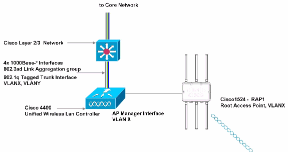
Now the network is ready to be populated with access points. In this image, a Cisco Mesh access point LAP1524 is connected to the Cisco Layer 2/3 switch. Ensure that the access point has joined the controller. On the first instance of joining a controller the access point is by default a Mesh access point (MAP). Ensure that the configuration of the access point is changed to a Root /Roof top access point (RAP). Cisco recommends that you configure the 802.11a radio for 54Mbits backhaul. Configure the bridge-group name and enable Ethernet bridging.
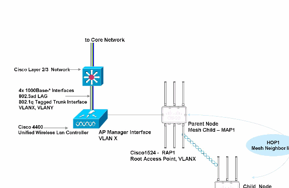
Add another access point to the network. This access point (MAP) joins the controller with the 802.11a radio as its backhaul interface. Verify that the access point joined the controller and also the Link SNR between the access points. Ensure the Link SNR is greater than or equal to 30db. This image illustrates that the access point joined the controller with 802.11a radio as its backhaul.
Note: Some caution needs to be taken when you install the access points. Make sure that there is a clear line-of-sight to the parent access point. For example, consider a linear network with one RAP and three MAPs (MAP1, MAP2, MAP3). MAP1 joins to RAP, MAP2 joins MAP1, MAP3 joins MAP2 and so on. Verify the Link SNR between the access points. Ensure that the Link SNR of each access point and its parent is greater that 30db.
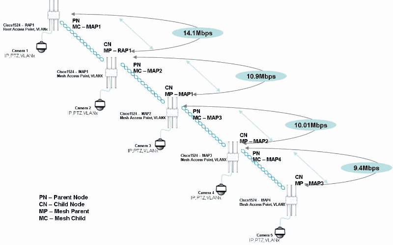
This image also explains the parent/child relationship as explained in the Mesh AP 1520 series deployment guide . The throughput that can be achieved with the recommended Link SNR is also show in this figure. With the backhaul data rate of 54Mbits, and no 802.11b/g client traffic, throughput as high as 14.1Mbits can be achieved. The throughput mentioned here is based on the distance between the access points and also the power levels configured on the access points. These performance numbers are limited only for the outdoor setup where the access points are installed at a particular location. The performance numbers can vary from installation to installation.
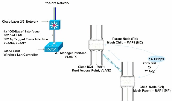
Add the final access points to the network and ensure that all the MAPs have joined the controller. The parent/child relationship and the data throughput is articulated in this figure.
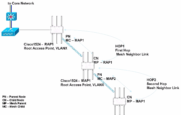
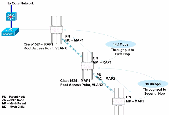
This figure illustrates a three hop network with the parent/child relationship and also the throughput data that can be achieved with no client traffic.
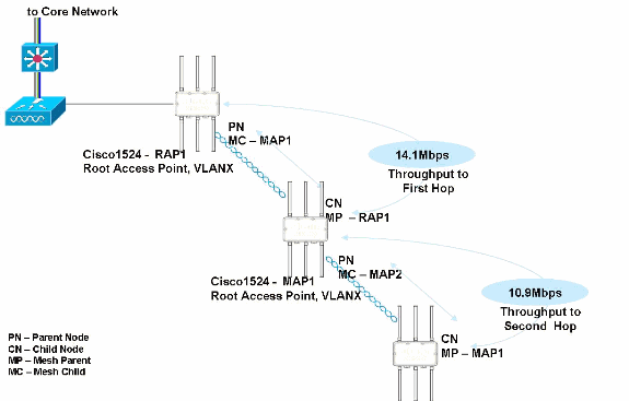
Note: Some caution needs to be taken when you install the access points. Make sure that there is a clear line-of-sight to the parent access point. For example consider a linear network like with one RAP and three MAPs (MAP1, MAP2, MAP3). MAP1 joins to RAP, MAP2 joins MAP1, MAP3 joins MAP2 and so on. Verify the Link SNR between the access points. Ensure that the Link SNR of each access point and its parent is greater that 30db.
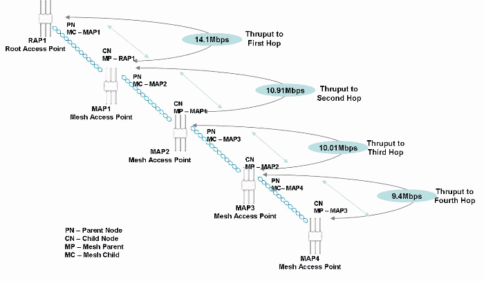
This figure illustrates a four hop network with the parent/child relationship and also the throughput data that can be achieved with no client traffic.
Note: The mesh access points need to be powered with the AC input connector. A mesh access point powered with a power injector or power over Ethernet does not provide sufficient power to turn on the camera connected to the POE out port on the Cisco Mesh access point.
Verify the mesh network. This figure shows that the RAP and the MAPs joined the controller. This can also be verified through the CLI. The show ap summary command gives you the list of access points that have joined the controller.
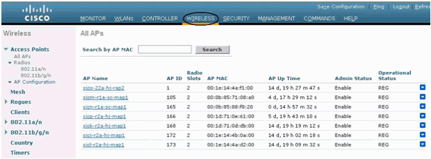
When you verify the parent/child relationship and the Link SNR, you can see that almost all the access points have a Link SNR of 30db. In order to verify this, click the pull-down arrow to the right of the screen, and click Neighbor Information.
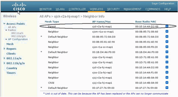
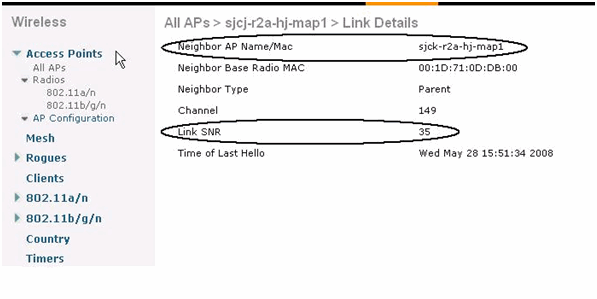
Click the pull down arrow to choose details. This gives you more details of the Link SNR. Also verify the parent access point.
Ethernet Bridging
For security reasons the Ethernet port on all MAPs is disabled by default. It can be enabled only if you configure Ethernet Bridging on the root and its respective MAPs. Ethernet bridging must be enabled in two scenarios:
-
When you want to use the Mesh nodes as bridges.
-
When you want to connect any Ethernet device, such as a video camera on the MAP that uses its Ethernet port.
This is the first step to enable VLAN tagging.
Use the GUI to Enable Ethernet Bridging
Make sure that Ethernet bridging is enabled on the all of the devices for traffic to flow. Bridging must be enabled on the RAP and MAPs, which can be verified as shown in this image.
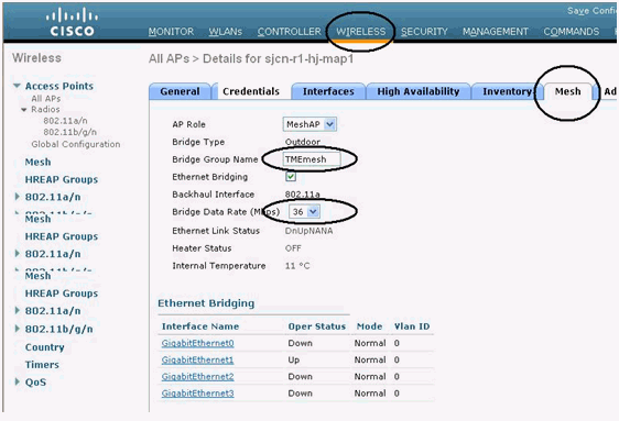
This figure also shows a Bridge Group name (BGN) configured. BGN logically groups the APs and can be used to sectorize the mesh network. Mesh access points can be placed in the same bridge groups to manage membership or provide network segmentation.
This figure also shows the backhaul data rate configuration. When you design and build a wireless mesh network, there are a few system characteristics to consider. Some of these apply to the backhaul network design and others to the CAPWAP controller design:
-
36 Mbps is chosen as the optimal backhaul rate because it aligns with the maximum coverage of the client WLAN of the MAP. The distance between MAPs with 36 Mbps backhaul must allow for seamless WLAN client coverage between the MAPs.
-
A lower bit rate can allow a greater distance between mesh access points, but there are likely to be gaps in the wireless client coverage, and as a result the capacity of the backhaul network is reduced.
-
An increased bit rate for the backhaul network either requires more mesh access points or results in a reduced SNR between mesh access points, which limits mesh reliability and interconnection.
-
The wireless mesh backhaul bit rate set on the controller, like the mesh channel, is set by the RAP.
Refer to Cisco 1520 Mesh User guide for details on Ethernet VLAN Tagging.
Video Deployment Guidelines
With the introduction of video traffic, there are few data points that need to be understood. These are the metrics that define the video bandwidth and quality. Some of the metrics used by the camera vendors are different and are not common across all the camera vendors.
Refer to Appendix.
Video Resolution
Video Resolution is a measure of the ability of a camera, encoder or video system to reproduce detail. In analog systems, resolution usually refers to the number of lines that make up an image. Whereas with digital systems, resolution gives a measure of the number of pixels used to generate the image. This is always addressed as Common Intermediate Format (CIF).
Common Intermediate Format (CIF)
The term CIF is used to mean specific video resolution: 352x288 in PAL 352x240 in NTSC.
| Format | NTSC Based | PAL Based |
|---|---|---|
| QCIF | 176*120 | 176*144 |
| CIF | 352*240 | 352*288 |
| 2 CIF | 702*240 | 702*576 |
| 4 CIF | 704*480 | 704*576 |
| D1 | 720*480 | 720*576 |
| Format | NTSC Based | PAL Based |
|---|---|---|
| QQVGA | 160*120 | 160*120 |
| QVGA | 320*240 | 320*240 |
| VGA | 640*480 | 640*480 |
Video Bit-Rate
Video quality is a factor of two components: Video resolution and Video bit-rate. Video bit-rate is measured as the amount of video traffic and is always quantified in Mbits/sec. Video bit-rate can range from 512kbps to 8Mbps.
Frames Per Second (FPS)
FPS is a measure of the rate of output of single snapshots of a camera, also known as images per second and frame rate.
Pan-tilt-zoom (PTZ)
PTZ is the capability to change a field of view of a camera through three planes of reference. Pan refers to the physical movement of a camera from side-to-side (xy-plane), whereas tilt is the ability to move it up-and-down (azimuth). Zoom changes the lens magnification of a camera and gives the visual effect that the point-of-focus is closer or further away.
If there is a functional Cisco Mesh network in accordance with the Mesh design guidelines recommended, this bandwidth can be achieved under test conditions. These are the throughput numbers achieved with no data traffic on the access points .
| First Hop | Second hop | Third Hop | Fourth hop |
|---|---|---|---|
| 14.1Mbps | 10.9Mbps | 10.01Mbps | 9.43Mbps |
Note: This configuration and throughput can be achieved under test conditions / Green field installations. The throughput numbers vary with installations, because it is dependent directly on the distances (cell sizes) and also the Link SNRs. Refer to for more information.
Note: The introduction of one camera at each hop simultaneously configured for 2 Mbps, 30 fps and 4CIF resolution, the configured Mesh network with an Ethernet attached camera is illustrated in this figure.
This table gives a rough estimate of camera traffic on a wire at different configurations.
| 10 fps | 15 fps | 30 fps | |
|---|---|---|---|
| CIF | 0.78 Mbps | 1.03 Mbps | 1.35 Mbps |
| 4 CIF | 1.56 Mbps | 1.92 Mbps | 2.32 Mbps |
Each camera is estimated to generate about 2.32Mbps of traffic on the backhaul radio. This includes the PTZ traffic that is generated on each of the cameras as they scan the area.
In order to introduce some complexity into the design, add client traffic on the 802.11b/g radio with additional wireless cameras. It is recommended that the wireless camera also maintain the similar SNR (>30db) as mentioned for the mesh access point to the parent.
This figure explains the different camera configurations that are introduced into the Mesh network. These are some of the standard configuration templates that are used. Read carefully and understand the impact on the Mesh network.
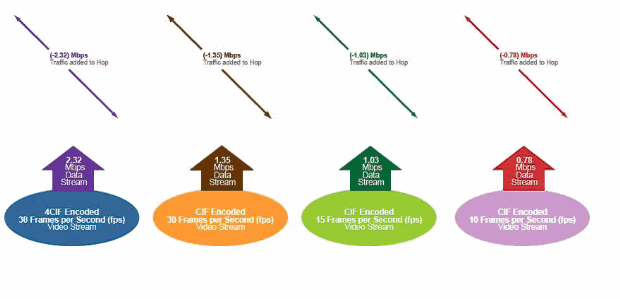
Start from left to right in this figure. The first icon generates about 2.32Mbps traffic on the wire/backhaul per camera. This configuration is with a combination of 4CIF, 30 fps and 2Mbit stream. The second icon generates about 1.35Mbps traffic on the wire/backhaul per camera. This configuration is with CIF, 30fps and 1Mbit stream. The third icon generates about 1.03Mbps traffic on the wire/backhaul per camera. This configuration is with CIF, 15fps and 1Mbit stream. The last icon generates about 0.78Mbps traffic on the wire/backhaul per camera. This configuration is with CIF, 10 fps and 0.512Mbit stream. With this camera configuration and with the available throughput, the next figure illustrates the available combinations on the cameras at different hops. The figure clearly shows the camera configuration and the impact on the mesh backhaul link.
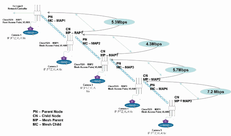
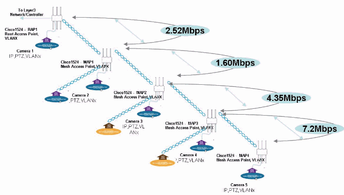
When one camera is introduced at each hop, the impact on the backhaul can be observed. From the fourth hop, MAP4, with the introduction of a camera with a configuration of 4CIF, 30fps and 2Mbits, there is 7.2Mbps of bandwidth available. This also impacts the bandwidth up to the RAP as the camera traffic path passes the backhaul radio of the access points in the path.
The introduction of a camera with a similar configuration on MAP3 does not impact the bandwidth on HOP4. The impact is on HOP3 as this hop has traffic from two cameras now. The available bandwidth on this hop is 5.7Mbps. If you add the same configuration camera on MAP2, it impacts its upstream link, HOP2. These hops carry traffic from three cameras and hence the available bandwidth is approximately 4.3Mbps. If you repeat the same exercise on MAP1, HOP1 carries traffic from four cameras. Hence the available bandwidth is 5.3Mbps. With these calculations, it is clearly understood that we can have only five Ethernet cameras with a resolution of 4CIF, 30fps and 2Mbits configured on the proposed serial deployment.
Note: This configuration and throughput can be achieved under test conditions/installations. The throughput numbers vary with installations as it is dependent directly on the distances (cell sizes) and also the Link SNRs. Refer to Cell Planning and Distance for more information.
This shows the impact on camera traffic on the backhaul. The introduction of some complexity into the design when wireless cameras are added increases client traffic on the 802.11b/g radio. It is recommended that the wireless camera also maintain the similar SNR (>30db) as mentioned for the mesh access point to the parent. The next section discusses whether it is possible to associate cameras with the same configurations to the WLC.
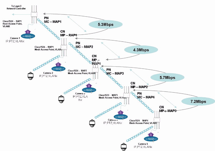
Can all wireless cameras match the configuration of the wired cameras attached? This diagram explains the impact with a similar configuration.
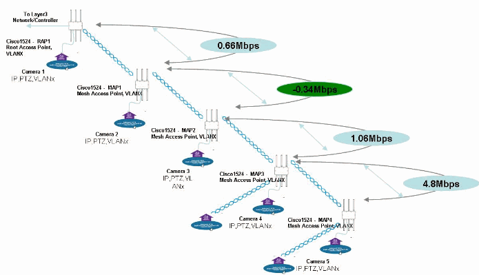
If you add a Cisco 2500IP wireless camera to the wireless mesh network, it adds some more complexity into the backhaul bandwidth. The Cisco 2500IP wireless cameras are placed such that the SNR value is maintained at 30db or greater. The distance from the wireless camera to the access point can vary based on the type of environment. Add one wireless camera with the standard configuration on the camera and it generates around 2.24Mbps traffic on the wire. With this addition on MAP4, the backhaul bandwidth is limited to 4.8Mbps. Since this is a serial back haul configuration, there is an equal impact on the upstream backhaul links. If you add one more wireless camera on MAP3, it has a serious implication on HOP1 as there is not sufficient bandwidth. In this scenario, the result is that you over shoot the back haul bandwidth calculations. Since there is not much bandwidth available at the second hop, it is not recommended to add a camera as there is no video across the link from the wireless camera on the third and fourth hop.
The final topology with cameras connected in this scenarios is shown in the next figure. The topology is smartly configured with Ethernet attached cameras on all MAPs with each camera loading 2.32Mbps on the backhaul. MAP1 has an Ethernet attached camera and a wireless camera configured with 4CIF, 30 frames and 2 Mbit stream. MAP2 has an Ethernet attached camera configured with 4CIF, 30 frames and 2 Mbit stream and wireless camera configured for CIF, 30 frames and 1Mbit stream. MAP3 has an Ethernet attached camera configured with 4CIF, 30 frames and 2 Mbit stream and wireless camera configured for CIF, 30 frames and 1Mbit stream. MAP4 has an Ethernet attached camera configured with 4CIF, 30 frames and 2 Mbit stream.
This table gives an estimate of the number of cameras installed per sector with different configurations.
| Video Resolution | Video Bitrate (CBR) | Video Frames (fps) | # of Cameras Supported / Sector |
|---|---|---|---|
| 4 CIF / MPEG 4 | 2 Mbps | 15 | 11-13 |
| 4 CIF / MPEG 4 | 2 Mbps | 30 | 10 |
| CIF / MPEG 4 | 2 Mbps | 15 | 10-12 |
| CIF / MPEG 4 | 2 Mbps | 30 | 8-10 |
| 4 CIF / MPEG 4 | 2 Mbps | 15 | 9-10 |
| 4 CIF / MPEG 4 | 2 Mbps | 30 | 10-12 |
| CIF / MPEG 4 | 2 Mbps | 15 | 13-14 |
| CIF / MPEG 4 | 2 Mbps | 30 | 11-12 |
Note: Cameras supported/sector is derived from the Cell planning guide for Mesh access points. Refer to Cell Planning and Distance for more information.
Summary
Cisco mesh architecture for video surveillance when deployed with these guidelines, works efficiently to provide safe and secure surroundings. Cisco mesh access points can be used as a carrier for the video traffic from the cameras attached to the Video server /DVR.
Supported Cameras
These cameras are supported and tested for interoperability with Cisco Mesh access points.
-
Cisco 2500 Series Video Surveillance IP camera – Outdoor Housing Required—Cisco Video Surveillance IP Camera
-
Pelco Spectra IV IP Series Network Dome System—Spectra ® IV IP Series Network Dome System
-
Sony SNCRX550N/RX570N 360deg P/T/Z IP Camera – Outdoor Housing Required—SNCRX570N/W Network Rapid Dome Camera, Dual Stream JPEG/MPEG-4, H.264, Day/Night, 36x Optical Zoom, White
Appendix-Video Terminology
| Terminology | Definition |
|---|---|
| Alert | A message sent to security personnel that indicates the location and nature of an emergency or threat. |
| Attenuation | A decrease or loss of signal. Within a fiber or coaxial-cabled surveillance system, this causes degradation in the video image (e.g. jitter, noise, loss of signal). |
| Camera | An optical device that is able to view a given area and translate that view into an electronic signal. |
| Central Station | A remote location that is designed to monitor signals from physical security systems. |
| Channel | A single video signal. |
| Closed-Circuit Television (CCTV) | A television system in which signals are distributed with cables to a closed network of monitors. This system is most often used for security surveillance in small, closed areas like buildings or parking garages. |
| Coaxial Cable | Sometimes referred to as Coax. A type of cable that is able to pass a range of frequencies with low loss. It consists of a hollow metallic shield in which one or more center conductors are put in place and isolated from one another and from the shield. |
| Common Intermediate Format (CIF) | The term CIF is used to mean specific video resolution: 352x288 in PAL 352x240 in NTSC. CIF is 1/4th of "full resolution" TV, also called D1 |
| Console (CCTV) | The part of a monitoring station an operator uses to control surveillance cameras. Usually consists of a joystick for PTZ control and a set of numbered buttons that allow the operator to switch cameras displayed on an attached monitor. It can also refer to the entire structure at a monitoring station that houses the keyboards, joysticks, monitors, phones, etc. used to control the physical security system. |
| Contrast | The ratio of light to dark portions of a video image. |
| Day and Night | Refers to the ability of a video camera to change the image format from color to black-and-white in order to provide images in both light and dark conditions, respectively. |
| Decoder | A hardware or software device that employs a codec to translate a signal from its digital form into an analog output for display on a monitor. |
| Depth of Field | The distance between two objects, front to back, which is in focus in a televised scene. With a greater depth of field, more of the scene, near to far, is in focus. |
| Digital PTZ | (aka, ePTZ). The capability to virtually pan-tilt-zoom within a digital image. The feature does not require the ability to mechanically move a camera or its focus. Currently an emerging feature of megapixel cameras. |
| Digital Video Recorder (DVR) | Digital Video Recorder is the industry standard term applied to PC-based or embedded systems that encode and record video images to a computer hard drive. DVRs offer a quicker method to retrieve the recorded information, unlike media such as VHS tapes and other equipment that stores information in a sequential manner. DVRs are often integrated into enterprise networks through a single Ethernet interface, yet they terminate multiple analog cameras, typically four, eight or sixteen. See also Network Video Recorder. |
| Dome Camera | A video imaging device contained within a demisphere. Generally supports the ability to change its focus (i.e. camera PTZ inside the dome) within the field-of-view allowable by the dome itself. |
| Encoder | A hardware or software device that employs a codec to translate an analog video signal into a digital form. |
| Field of View (FOV) | The area of focus of a camera (i.e. what it can see). |
| Frame | The total area of the picture that is scanned. With interlaced video, the frame is comprised of two fields. |
| Frame Rate | Frames Per Second |
| Frames Per Second (FPS) | A measure of a camera’s rate of output of single snapshots. Also known as images per second and frame rate |
| Horizontal Resolution | The maximum number of individual picture elements that can be distinguished in a single scanning line. |
| Image Size (Lenses) | Reference to the size of an image formed by the lens onto the camera pickup device. The current standards are: 1", 2/3”, ½”, 1/3” and 1/4” measured diagonally. |
| IP or Network Camera | A video imaging device that natively attaches to an Ethernet network and delivers its images in IP packets. It differs from its analog equivalents in that it does not require an external encoder to translate the video into a digital signal nor to attach to the IP network. |
| IP Video Surveillance (IPVS) | Refers to the system or process of monitoring an area with the use of an IP network as the transport for remote video signals. The components of an IPVS system include edge devices such as IP cameras, IP encoders, or DVRs; an IP network for transport; recording devices such as NVRs; monitoring stations including monitors and consoles served through decoders or PCs running monitoring software; and management software for configuration and maintenance. |
| Iris | The eye of a camera. An adjustable opening that controls the amount of light that enters a camera from its lens projected onto the imager of the camera. |
| Keypad | A device that provides a user interface to control a security system or subsystem. Typically includes a numerical 10-key touchpad that allows you to enter passcodes and commands. See also Console. |
| Level Control | Main iris control. Used to set the auto-iris circuit to a video level desired by the user. After setup, the circuit adjusts the iris to maintain this video level in varied lighting conditions. When the control is turned High, it opens the iris. Low closes the iris. |
| Manual Iris Lens | A lens with a manual adjustment to set the iris opening (F stop) in a fixed position. Generally used for fixed lighting applications. See also Fixed Iris Lens. |
| Matrix Switch | A video signal device able to route any of its inputs (i.e. cameras) to any of its outputs (i.e. Monitors and recorders). Through a matrix switch, the relation of inputs to outputs is a one-to-one connection unless a looping device is introduced. The actual number of inputs to outputs is generally not one-to-one. Inputs usually exceed the number of outputs available. Matrix switches are usually located at a security operations center, where all video concentrates and displays on multiple monitors. Users control the matrix with a joystick and keyboard that allows switching and the remote control of pan-tilt-zoom cameras. |
| Mega-Pixel Camera | An IP camera that is able to provide extremely detailed image resolution, on the order of HDTV quality. Mega-pixel loosely refers to a single image that contains multi-million pixels. |
| Monitor | A CRT used to display live and recorded analog video. |
| Monitoring | The transmission of an alarm, trouble, and other signals to a remote location such as a security operations center. |
| Motion Detection (Video) | A process that analyzes the video signal of a camera in order to determine if there is any movement (pixel changes) in the picture and then subsequently triggers an alarm. |
| Network Video Recorder (NVR) | A PC or network appliance that runs special software used to capture and store images that emanate from IP cameras and encoders. An NVR differs from a DVR in that it provides no encoding of analog video signals. In other words, it has no video inputs. Typically the NVR attaches to the source over an IP network in order to acquire video. See also Digital Video Recorder. |
| NTSC (National Television Systems Committee) | A committee that worked with the FCC to formulate the standards for the United States color television system. NTSC specifies a resolution of 480 lines at 30 frames per second. See also PAL. |
| Physical Security | The use of personnel, equipment, and procedures to control the access to a facility and its assets. |
| PTZ (Pan-tilt-zoom) | Describes the capability to change the field of view of a camera through three planes of reference. Pan means to physically sweep a camera from side-to-side (xy-plane), whereas tilt is the ability to move it up-and-down (azimuth). Zoom changes the lens magnification of a camera, which gives the visual effect that the point-of-focus is closer or further away. |
| Resolution | A measure of the ability of a camera, encoder or video system to reproduce detail. In analog systems, resolution usually refers to the number of lines that make up an image. Whereas with digital systems, resolution gives a measure of the number of pixels used to generate the image. |
| Security Operations Center (SOC) | The command center where security personnel monitor and respond to security and safety related incidents. |
| UTP | Unshielded twisted pair. A cable medium with one or more pairs of insulated twisted copper wires. |
| Zoom (Digital) | Magnify a video image with computational algorithms on the digital signal. |
| Zoom (Optical) | Magnify a video image with the focal length of a lens. |
| Zoom Lens | A lens that can be effectively used as a standard or telephoto lens through changes in its focal length. |
| Zoom Ratio | The ratio of the initial focal length (wide position) to the end focal length (telephoto position) of a zoom lens. A lens with a 10X zoom ratio magnifies the image at the wide-angle end by ten times. |
 Feedback