Indoor Mesh Deployment Guide
Available Languages
Contents
Introduction
The Lightweight Access Point 1242/1131 is a two-radio Wi-Fi infrastructure device for selected indoor deployments. It is a Lightweight Access Point Protocol (LWAPP)-based product. It provides a 2.4 GHz radio and a 5.8 GHz radio compatible with 802.11b/g and 802.11a. One radio can be used for local (client) access for the access point (AP) and the second radio can be configured for wireless backhaul. LAP1242/LAP1131 supports P2P, P2MP, and mesh type of architectures.
Make sure to read through the guide before attempting any of the installations.
This document describes the deployment of Enterprise Wireless Mesh for indoor mesh. This document will enable wireless end-users to understand the fundamentals of Indoor Mesh, where to configure indoor mesh, and how to configure indoor mesh. Indoor mesh is a subset of Cisco Enterprise Wireless Mesh deployed using wireless controllers and lightweight APs.
Indoor mesh is a subset of the Enterprise mesh architecture deployed on Unified Wireless architecture. Indoor mesh is in demand today. With indoor mesh, one of the radios (typically 802.11b/g) and/or the wired Ethernet link is used to connect to clients, while the second radio (typically 802.11a) is used to backhaul client traffic. The backhaul may be a single hop or over multiple hops. Indoor mesh brings these values to you:
-
Not having to run Ethernet wiring to each AP.
-
Ethernet switch port is not required for each AP.
-
Network connectivity where wires cannot provide connectivity.
-
Flexibility in deployment – not restricted to 100m from an Ethernet switch.
-
Easy to deploy an ad-hoc wireless network.
Big-box retailers are very attracted to indoor mesh because of the costs savings on wiring as well as for the reasons previously mentioned.
Inventory specialists use it n performing inventory counts for retailers, manufacturing plants, and other companies. They want to quickly deploy a temporary Wi-Fi network at a customer site to enable real-time connectivity for their handheld devices. Educational Seminars, conferences, manufacturing, and hospitality are some of the places where indoor mesh architecture is needed.
When you finish reading this guide, you will understand where to use and how to configure indoor mesh. You will also understand that indoor mesh in NEMA enclosures is NOT a replacement for outdoor mesh. Further, you will also understand the superiority of indoor mesh over link role flexibility (single hop mesh) used by autonomous APs.
Assumptions:
You have knowledge of Cisco Unified Wireless Network, architecture, and products. You have knowledge of Cisco Outdoor Mesh products and some of the terminology used for mesh networking.
| Glossary of Acronyms | |
|---|---|
| LWAPP | Lightweight Access Point Protocol – The control and data tunneling protocol between APs and the Wireless LAN Controller. |
| WLAN Controller /Controller /WLC | Wireless LAN Controller – Cisco devices that centralize and simplify network management of a WLAN by collapsing large number of managed end-points into a single, unified system, allowing for a unified intelligent information WLAN network system. |
| RAP | Root Access point/ Roof access point – Cisco wireless devices act as bridge between the controller and other wireless APs. APs that are wired to the controller. |
| MAP | Mesh APs – Cisco wireless device that connects to a RAP or a MAP over the air on a 802.11a radio and also services clients on a 802.11b/g radio. |
| Parent | An AP (either a RAP/MAP) that provides access to other APs over the air on a 802.11a radio. |
| Neighbor | All APs in a Mesh network are neighbors and have neighbors. RAP does not have a neighbor as it wired to the controller. |
| Child | An AP farther from the controller is always a child. A child will have one parent and many neighbors in a mesh network. If the parent dies, the next neighbor with the best ease value will be chosen parent. |
| SNR | Signal-to-Noise Ratio |
| BGN | Bridge Group Name |
| EAP | Extensible Authentication Protocol |
| PSK | Preshared Key |
| AWPP | Adaptive Wireless Path Protocol |
Overview
The Cisco Indoor Mesh Network Access Point is a two-radio Wi-Fi infrastructure device for selected indoor deployments. It is a Lightweight Access Point Protocol (LWAPP)-based product. It provides a 2.4 GHz radio and a 5.8 GHz radio compatible with 802.11b/g, 802.11a standards. One radio (802.11b/g) can be used for local (client) access for the AP and the second radio (802.11a) can be configured for wireless backhaul. It provides an indoor mesh architecture, where different nodes (radios) talk to each other via backhaul and also provide local client access. This AP can also be used for point-to-point and point-to-multipoint bridging architectures. The Wireless Indoor Mesh Network solution is ideal for large indoor coverage as you can have high data rates and good reliability with minimum infrastructure. These are the basic salient features introduced with the first release of this product:
-
Used in Indoor environment for a 3 hop-count. Maximum 4.
-
Relay node and host for end-user clients. An 802.11a radio is used as a backhaul interface and an 802.11b/g radio for servicing clients.
-
Indoor mesh APs security – EAP and PSK supported.
-
The LWAPP MAPs in a mesh environment communicate with the controllers in the same way as compared to Ethernet-attached APs.
-
Point-to-point wireless bridging.
-
Point-to-multipoint wireless bridging.
-
Optimal parent selection. SNR , EASE, and BGN
-
BGN enhancements. NULL and Default mode.
-
Local Access.
-
Parent black listing. Exclusion list.
-
Self Healing with AWPP.
-
Ethernet Bridging.
-
Basic support of Voice from the 4.0 release.
-
Dynamic Frequency Selection.
-
Anti stranding – Default BGN and DHCP failover.
Note: These features will not be supported:
-
4.9 GHz public safety channel
-
Routing Around Interference
-
Background Scanning
-
Universal access
-
Work Group Bridge Support
Indoor Mesh Software
Indoor Mesh Software is a special release as it concentrates on the indoor APs, especially indoor mesh. In this release, we have both the Indoor APs working in Local mode and also in bridge mode. Some of the features that are available in 4.1.171.0 release are not implemented in this release. Improvements have been made to the command line interface (CLI), graphical user interface (GUI – web browser) and on the state machine itself. The objective for these improvements is to gain valuable information from your perspective regarding this new product and its functional viability.
Indoor mesh specific enhancements:
-
Indoor Environment – Indoor mesh is implemented using LAP1242s and LAP1131. These are implemented in indoor environments where Ethernet cable is not available. The implementation is easy and faster to provide a wireless coverage to remote areas within the building (for example, Retail Distribution centers, Education for Seminars/conferences, Manufacturing, Hospitality).
-
Bridge Group Name (BGN) Enhancements – In order to allow a network administrator to organize a network of Indoor Mesh APs into user specified sectors, Cisco provides a mechanism called Bridge Group Name, or BGN. The BGN, really the sector name, causes an AP to connect to other APs with the same BGN. In the event an AP finds no suitable sector matching its BGN, the AP operates in default mode, and chooses the best parent that responds to the default BGN. This feature has already received a lot of appreciation from the field as it fights against the stranded AP conditions (if someone has mis-configured the BGN). In the 4.1.171.0 software release, the APs, when using the default BGN, does not operate as an indoor mesh node and does not have any client access. It is in maintenance mode to access via the controller, and if the administrator does not fix the BGN, the AP will reboot after 30 minutes.
-
Security Enhancements - Security on indoor mesh code is by default configured for EAP (Extensible Authentication Protocol). This is defined in RFC3748. Although the EAP protocol is not limited to wireless LANs and can be used for wired LAN authentication, it is most often used in wireless LANs. When EAP is invoked by an 802.1X enabled NAS (Network Access Server) device such as an 802.11 a/b/g Wireless Access Point, modern EAP methods can provide a secure authentication mechanism and negotiate a secure PMK (Pair-wise Master Key) between the client and NAS. The PMK can then be used for the wireless encryption session which uses TKIP or CCMP (based on AES) encryption.
Prior to the 4.1.171.0 software release, outdoor mesh APs used PMK/BMK to join the controller. This was a three-cycle process. Now the cycles are reduced for a faster convergence.
The overall goal of indoor mesh security is to provide:
-
Zero touch configuration for provisioning security.
-
Privacy and authentication for data frames.
-
Mutual authentication between the network and the nodes.
-
Ability to use standard EAP methods for authentication of indoor mesh AP nodes.
-
Decoupling LWAPP and indoor mesh security.
The discovery, routing, and syncing mechanisms are enhanced from the current architecture to accommodate the required elements to support the new security protocols.
Indoor mesh APs discover other mesh APs by scanning and listening for gratuitous neighbor updates from other mesh APs. Any RAP or indoor MAPs connected to the network advertises core security parameters in their NEIGH_UPD frames (much like 802.11 beacon frames).
Once this phase is over, a logical link between an indoor mesh AP and root AP is established.
-
-
WCS Enhancements
-
Indoor Mesh Alarms have been added.
-
Indoor Mesh Reports can be generated showing the hop count, worst SNR, etc.
-
Link test (Parent-to-Child, Child-to-Parent) can be run between the nodes which shows very intelligent information.
-
AP's information displayed is much more than the earlier ones.
-
One has an option to also view the potential neighbors.
-
Health monitoring is improved and more convenient to access.
-
Supported Hardware and Software
There is a minimum hardware and software requirement for indoor mesh:
-
Cisco LWAPP APs AIR-LAP1242AG-A-K9 and AIR-LAP1131AG-A-K9 support indoor mesh configuration.
-
Cisco Mesh Release 2 software supports Enterprise Mesh (Indoor and Outdoor products). This can be installed on Cisco Controller, Cisco 440x/210x, and WISMs only.
-
Cisco Enterprise Mesh Release 2 software can be downloaded from Cisco.com.
Indoor vs. Outdoor
These are some of the salient differences between indoor and outdoor mesh:
| Indoor Mesh | Outdoor Mesh | |
|---|---|---|
| Environment | Indoor ONLY, hardware indoor rated | Outdoor ONLY, Rugged hardware |
| Hardware | Indoor AP using LAP1242 and LAP1131AG | Outdoor AP using LAP15xx and LAP152x |
| Power Levels | 2.4 Ghz:20dbm 5.8 Ghz:17dbm | 2.4 Ghz:28dbm 5.8 Ghz:28dbm |
| Cell sizes | Approx 150ft | Approx 1000ft |
| Implementation height | 12ft from the ground | 30-40ft from the ground |
Configuration
Make sure to review the guide thoroughly before starting any implementation, especially if you have received new hardware.
Controller L3 mode
Indoor mesh APs can be deployed as an L3 network.
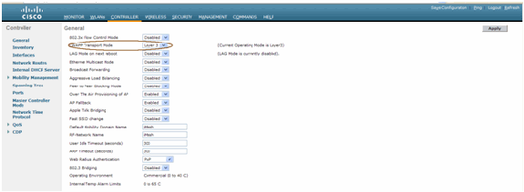
Upgrade the Controller to the Latest Code
Complete these steps:
-
For upgrading Mesh Release 2 on an indoor mesh network, your network must be running on 4.1.185.0 or Mesh Release1, available on Cisco.com.
-
Download the latest code for the Controller to your TFTP server. From the Controller GUI interface, click Commands > Download file.
-
Select the File type as code and give the IP address of your TFTP server. Define the path and the name of the file.

Note: Use the TFTP Server that supports more than 32 MB File size transfers. For example, tftpd32. Under File path put “ ./” as shown.
-
When finished installing the new firmware, use the show sysinfo command in the CLI to verify that the new firmware is installed.
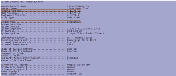
Note: Officially, Cisco does not support Downgrades for controllers.
MAC Address
It is mandatory to use MAC Filtering. This feature has made the Cisco Indoor Mesh solution as a real “Zero Touch.” Unlike the previous releases, the Mesh screen will no longer have the MAC Filtering option.

Note: MAC filtering is enabled by default.
Record MAC Address to the Radios
In a text file, record the MAC addresses of all the indoor mesh AP radios you deploy in your network. The MAC address can be found on the back of the APs. This helps you for future testing, as most of the CLI commands require the APs MAC address or names be entered with the command. You can also change the name of the APs to something more easily remembered, such as, “building number-pod number-AP type: last four MAC address hex characters.”
Enter MAC Address and the Names of the Radios in the Controller
The Cisco Controller maintains an indoor AP authorization MAC address list. The controller responds only to discovery requests from the indoor radios that appear on the authorization list. Enter the MAC addresses of all the radios which you tend to use in your network on the Controller.
On the Controller GUI interface, go to Security, and click on MAC filtering on the left side of the screen. Click New in order to enter the MAC addresses as shown here:
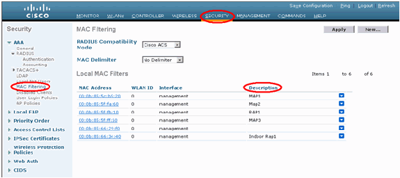
Also, enter the names of the radios for convenience under Description (such as location, AP #, etc.) Description can also be used for where the Radios have been installed for easy reference any time.
Enable MAC Filtering
MAC Filtering is enabled by default.
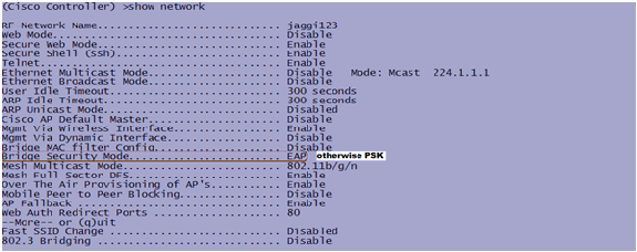
One can also make a choice of Security mode as EAP or PSK on the same page.
From the GUI interface of the switch, use this path:
GUI Interface Path: Wireless > Indoor Mesh
Security mode can ONLY be checked on the CLI by this command:
(Cisco Controller) > show network

L3 Indoor Mesh Deployment
For an L3 Indoor Mesh Network, configure the IP addresses for the radios if you do not intend to use the DHCP server (internal or external).
For an L3 Indoor Mesh Network, if you want to use DHCP server, configure the controller in L3 mode. Save the configuration and reboot the Controller. Make sure you configure Option 43 on the DHCP server. After the Controller has restarted, newly connected APs will receive their IP address from the DHCP server.
Define Interfaces on Controller
AP Manager
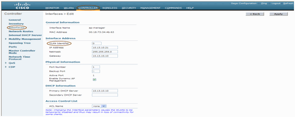
For an L3 deployment, you must define the AP-manager. The AP Manager acts as a source IP address for communication from the Controller to the APs.
Path: Controller > Interfaces > ap-manager > edit.

The AP-manager interface should be assigned an IP address in the same subnet and VLAN as your management interface.
Radio Roles
There are two primary radio roles possible with this solution:
-
Root Access Point (RAP) - The radio with which you want to connect to the Controller (via switch) will take the role of a RAP. The RAPs have a wired, LWAPP-enabled connection to the Controller. A RAP is a parent node to any bridging or indoor mesh network. A controller can have one or more RAP, each one parenting the same or different wireless networks. There can be more than one RAP for the same indoor mesh network for redundancy.
-
Indoor Mesh Access Point (MAP) - The radio which has no wired connection to the Controller takes the role of a indoor mesh AP. This AP was formerly called Pole top AP. MAPs have a wireless connection (through the backhaul interface) to perhaps other MAPs and finally to a RAP and thus to the controller. MAPs may also have a wired Ethernet connection to a LAN and serve as a bridge endpoint for that LAN (using a P2P or P2MP connection). This can occur simultaneously, if configured properly as an Ethernet Bridge. MAPs service clients on the band not used for the Backhaul Interface.
The default mode for an AP is MAP.
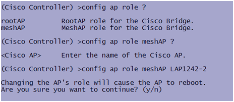
Note: The radio roles can be set via GUI or CLI. The APs will reboot after the role change.
Note: You can use the Controller CLI to pre-configure the radio roles on an AP provided the AP is physically connected to the switch or you can see the AP on the switch as a RAP or a MAP.
Bridge Group Name
Bridge Group Names (BGN) controls the association of the APs. BGNs can logically group the radios to avoid two networks on the same channel from communicating with each other. This setting is also useful if you have more than one RAP in your network in the same sector (area). The BGN is a string of ten characters maximum.
A factory-set bridge group name is assigned at the manufacturing stage (NULL VALUE). It is not visible to you. As a result, even without a defined BGN, the radios can still join the network. If you have two RAPs in your network in the same sector (for more capacity), it is recommended that you configure the two RAPs with the same BGN, but on different channels.
Note: Bridge Group Name can be set from the Controller CLI and GUI.

After configuring the BGN, the AP will reset.
Note: The BGN should be configured very carefully on a live network. You should always start from the farthest node (last node) and move towards the RAP. The reason is that if you start configuring the BGN somewhere in the middle of the multihop, then the nodes beyond this point will be dropped as these nodes will have a different BGN (old BGN).
You can verify the BGN by issuing this CLI command:
(Cisco Controller) > show ap config general <apname>
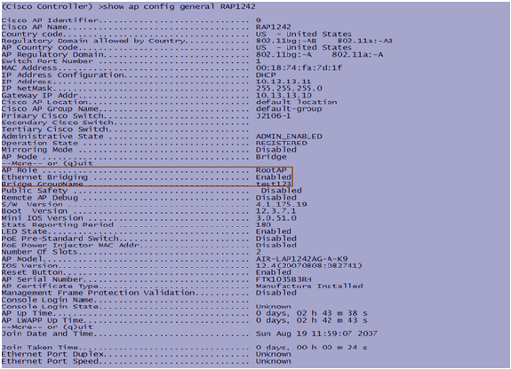
Also, you can configure or verify the BGN using the Controller GUI:
Path: Wireless > All APs > Details.

You can see that the AP’s Environmental information is also displayed with this new release.
Security Configuration
The default indoor mesh security mode is EAP. This means that unless you configure these parameters on your Controller, your MAPs will not join:


If you need to remain in PSK mode, use this command to go back to PSK mode:

Indoor Mesh EAP show Commands
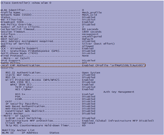
Within EAP mode, you can check these show commands to verify the MAP authentication:
(Cisco Controller) >show wlan 0
(Cisco Controller) >show local-auth config
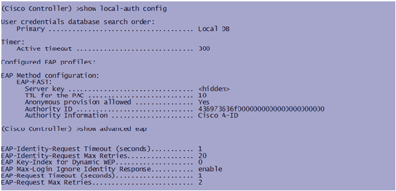
(Cisco Controller) >show advanced eap
Indoor Mesh EAP debug Commands
In order to debug any EAP mode problems, use these commands in the Controller:

Installation
Pre-requisites
The Controller must be running the recommended version of code. Click Monitor to verify the Software version. The same can be verified via CLI.
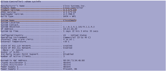
Systems like the DHCP server, ACS server, and WCS server should be reachable.
Installation
-
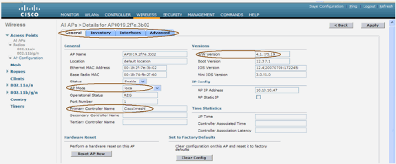
Connect all the LAPs (1131AG/1242AG) to a Layer 3 network on the same subnet as the Management IP address. All the APs will join the controller as APs in Local Mode. In this mode, prime the APs with the Primary controller name, Secondary controller name, and a Tertiary controller name.
-
Capture the Base radio MAC address of the AP (for example, 00:18:74: fb: 27:60).
-
Add the MAC address of the AP for the AP to join in bridge mode.
-
Click Security > MAC-filtering > New.
-
Add the copied MAC address, and name the APs in the MAC-filter list and the AP list.
-
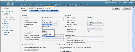
Choose Bridge from the AP Mode list.
-
It will prompt you to confirm as this will reboot the AP.

-
The AP will reboot and join the controller in Bridge mode. The new AP window will have an extra tab: MESH. Click the MESH tab to verify the role, bridge type, bridge group name, Ethernet bridging, back haul interface, bridge data rate, etc.

-
In this window, access the AP role list and choose the relevant role. In this case, the role by default is a MAP.
-
Bridge Group name is empty by default.
-
Back haul interface is 802.11a.
-
Bridge data rate (that is, Back haul data rate) is 24Mbps.
-
-
Connect the AP that you want as a RAP to the controller. Deploy the radios (MAPs) at the desired locations. Switch on the radios. You should be able to see all the radios on the controller.

-
Try to have line-of-sight conditions between the nodes. If line-of-sight conditions do not exist, create Fresnel zone clearances to obtain near-line-of-site conditions.
-
If you have more than one controller connected to the same indoor mesh network, then you must specify the name of the primary controller on every node. Otherwise, the controller which is seen first will be taken as the primary.
Power and Channel Configuration
The backhaul channel can be configured on a RAP. MAPs will tune to the RAP channel. The local access can be configured independently for MAPs.
From the Switch GUI, follow the path: Wireless > 802.11a radio > configure.
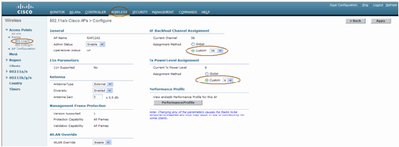
Note: Default Tx power level on the backhaul is the highest power level (Level 1) and Radio Resource Management (RRM) is OFF by default.
If you are collocating RAPs, we recommend you use alternate adjacent channels on each RAP. This will reduce co-channel interference.
RF Check
In an indoor mesh network we must verify the Parent-Child relationship between the nodes. Hop is a wireless link between the two radios. The Parent-Child relationship changes as you travel through the network. It depends upon where you are in the indoor mesh network.
The radio closer to the controller in a wireless connection (hop) is a Parent of the radio on the other side of the hop. In a multiple hop system there is a tree-type structure where the node connected to the Controller is a RAP (Parent). The immediate node on the other side of the first hop is a Child, and subsequent nodes in the second hop onwards are the Neighbors for that particular Parent.
Figure 1: Two Hop Network 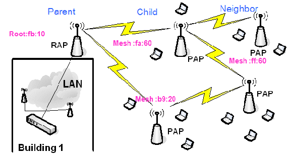
In Figure 1, AP names are mentioned for convenience. In the next screen shot, the RAP(fb:10) is being investigated. This node can see (in the actual deployment) the Indoor Mesh APs (fa:60 & b9:20) as children and MAP ff:60 as neighbor.
From the switch GUI interface, follow the path: Wireless > All APs > Rap1 > Neighbor Info.

Ensure that Parent-Child Relations are established and maintained correctly for your Indoor Mesh Network.
Verify the Interconnections
show Mesh is an informative command to verify interconnectivity in your network.
You must give these commands at each node (AP) using the Controller CLI, and upload the results in a Word or text file to the uploading site.

In your indoor mesh network, choose a multiple hop link and issue these commands starting from the RAP. Upload the result of the commands to the uploading site.
In the next section, all of these commands have been issued for the Two Hop Indoor Mesh Network shown in Figure 1.
Show Indoor Mesh Path
This command will show you the MAC addresses, radio roles of the nodes, Signal to Noise Ratios in dBs for Uplink/Downlink (SNRUp, SNRDown), and Link SNR in dB for a particular path.

Show Indoor Mesh Neighbor Summary
This command will show you the MAC addresses, parent-child relationships, and Uplink/Downlink SNRs in dB.
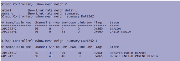
By this time, you should be able to see the relationships between the nodes of your network and verify the RF connectivity by seeing the SNR values for every link.
AP Console Access Security
This feature gives enhanced security to the console access of the AP. A console cable for the AP is required to use this feature.
These are supported:
-
A CLI to push the user-id/password combination to the specified AP:

-
A CLI command to push the username/password combination to all the APs registered to the Controller:

With these commands, the userid/password combination pushed from the controller is persistent across the reload on the APs. If an AP is cleared from the controller, there is no security access mode. The AP generates an SNMP trap with a successful login. The AP will also generate an SNMP trap on a console login failure for three consecutive times.
Ethernet Bridging
For security reasons, the Ethernet port on the MAPs is disabled by default. It can be enabled only by configuring Ethernet Bridging on the RAP and the respective MAPs.
As a result, Ethernet Bridging has to be enabled for two scenarios:
-
When you want to use the indoor mesh nodes as bridges.
-
When you want to connect any Ethernet device (such as PC/Laptop, video camera etc.) on the MAP using its Ethernet port.
Path: Wireless > Click any AP > Mesh.

There is a CLI command which can be used to configure the distance between the nodes doing the Bridging. Try connecting an Ethernet device like a Video Camera at every hop and see the performance.
Bridge Group Name Enhancement
It is possible that an AP is wrongly provisioned with a “bridgegroupname” for which it was not intended. Depending on the network design, this AP may or may not be able to reach out and find its correct sector/tree. If it cannot reach a compatible sector, it may become stranded.
In order to recover such a stranded AP, the concept of ‘default’ bridgegroupname was introduced with the 3.2.xx.x code. The basic idea is that an AP that is unable to connect to any other AP with its configured bridgegroupname, attempts to connect with “default” (the word) as bridgegroupname. All nodes running 3.2.xx.x and later software accept other nodes with this bridgegroupname.
This feature can also help in adding a new node or a wrong configured node to a running network.
If you have a running network, take a preconfigured AP with a different BGN and make it join the network. You will see this AP in the controller using “default” BGN after you add its MAC address in the controller.

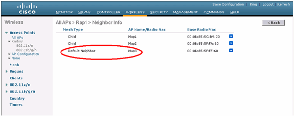
The AP using the default BGN can act as a normal Indoor Mesh AP associating clients and forming Indoor Mesh parent child relationships.
The moment this AP using the default BGN finds another parent with the correct BGN, it will switch to it.
Logs - Messages, Sys, AP, and Trap
Message Logs
Enable the reporting level for message logs. From the controller CLI, issue this command:

To see Message Logs, issue this command from the Controller CLI:
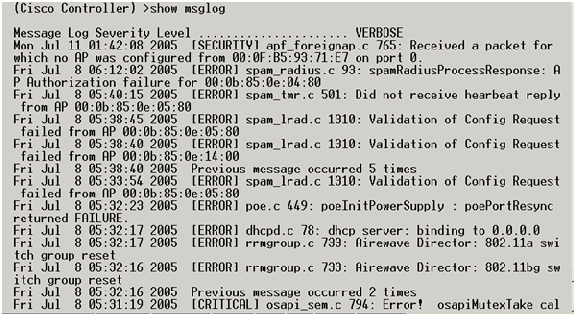
To upload the Message Logs, use the Controller GUI interface:
-
Click Commands > Upload.

-
Enter your TFTP server information. This page will give you various options to upload, and you want these files to be sent:
-
Message Log
-
Event Log
-
Trap Log
-
Crash File (if any)
In order to check for Crash files, click Management > Controller Crash.
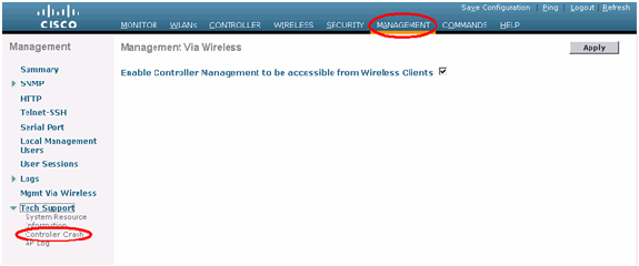
-
AP Logs
Go to this GUI page on the controller to check the AP logs for your local AP, if any:
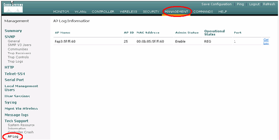
Trap Logs
Go to this GUI page of the Controller and check the Trap Logs:
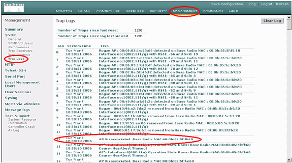
Performance
Startup Convergence Test
Convergence is the time taken by a RAP/MAP to establish a stable LWAPP connection with a WLAN controller starting from the time when it first booted up as listed here:
| Convergence Test | Convergence Time (min:sec) | |||
|---|---|---|---|---|
| RAP | MAP1 | MAP2 | MAP3 | |
| Image Upgrade | 2:34 | 3:50 | 5:11 | 6:38 |
| Controller Reboot | 0:38 | 0:57 | 1:12 | 1:32 |
| Power On Indoor Mesh Network | 2:44 | 3:57 | 5:04 | 6:09 |
| RAP reboot | 2:43 | 3:57 | 5:04 | 6:09 |
| MAP re-join | 3:58 | 5:14 | 6:25 | |
| MAP change of parent (same channel) | 0:38 | |||
WCS
Indoor Mesh Alarms
WCS will generate these alarms and events related to the indoor mesh network based on the traps from the Controller:
-
Poor Link SNR
-
Parent Changed
-
Child moved
-
MAP Changes parent frequently
-
Console port event
-
MAC Authorization failure
-
Authentication failures
-
Child excluded Parent
Click Mesh Links. It will show all the alarms related to indoor mesh links.
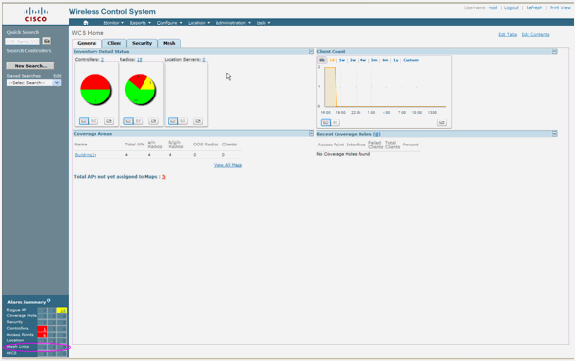
These Alarms apply to indoor mesh links:
-
Poor link SNR - This alarm is generated if link SNR falls below 12db. The user cannot change this threshold. If poor SNR is detected on the backhaul link for child/parent, the trap will be generated. The trap will contain SNR value and the MAC addresses. Alarm Severity is Major. SNR (signal-to-noise) ratio is important because high signal strength is not enough to ensure good receiver performance. The incoming signal must be stronger than any noise or interference that is present. For example, it is possible to have high signal strength and still have poor wireless performance if there is strong interference or a high noise level.
-
Parent changed - This alarm is generated when the child moved to another parent. When the parent is lost, the child will join with another parent, and the child will send a trap containing both old parent and new parent’s MAC addresses to WCS. Alarm Severity: Informational.
-
Child moved - This alarm is generated when WCS gets a Child lost trap. When the parent AP detected its loss of a child and not able to communicate with that child, it will send a Child lost trap to WCS. The trap will contain the child MAC address. Alarm Severity: Informational.
-
MAP parent changed frequently - This alarm is generated if Indoor Mesh AP changes its parent frequently. When MAP parent-change-counter exceeds the threshold within a given duration, it will send a trap to WCS. The trap will contain the number of times of MAP changes and the duration of the time. For example, if there are 5 changes within 2 minutes, then the trap will be sent. Alarm Severity: Informational.
-
Child Excluded Parent - This alarm is generated when a child blacklisted a parent. A child can blacklist a parent when the child failed to authenticate at the Controller after a fixed number of attempts. The child remembers the blacklisted parent and when the child joins the network, it will send the trap which contains the Blacklisted Parent MAC address and the duration of the blacklist period.
Alarms other than indoor mesh links:
-
Console Port Access - The console port provides the ability for the customer to change the user name and password to recover the stranded outdoor AP. However, to prevent any authorized user access to the AP, WCS needs to send an alarm when someone tries to log in. This alarm is required to provide protection as the AP is physically vulnerable while located outdoors. This alarm will be generated if the user has successfully logged in to the AP console port, or if he has failed three consecutive times.
-
MAC Authorization Failure - This alarm is generated when AP tries to join the Indoor Mesh but fails to authenticate because it is not in the MAC filter list. WCS will receive a trap from the Controller. The trap will contain the MAC address of the AP which failed authorization.
Mesh Report and Statistics
We carry over the enhanced report and statistics framework from 4.1.185.0:
-
No Alternate Path
-
Mesh Node Hops
-
Packets error Stats
-
Packet Stats
-
Worst Node Hop
-
Worst SNR Links
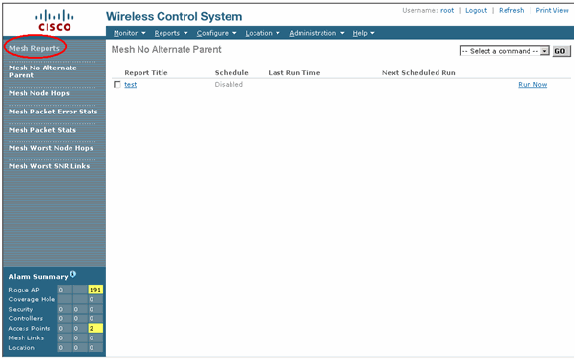
No Alternate Path
Indoor Mesh AP typically has more than one neighbor. In the case that an indoor mesh AP looses its parent link, the AP should be able to find the alternate parent. In some case, if there are no neighbors shown, then the AP will not be able to go to any other parents if it looses its parents. It is critical for the user to know which APs do not have alternate parents. This report lists out all the APs which do not have any other neighbors other than the current parent.
Indoor Mesh Node Hops
This report shows the number of hops away from the Root AP (RAP). You can create the report based on these criteria:
-
AP By Controller
-
AP By Floor
Packet Error Rates
The packet errors can be caused by interference and packet drops. The packet error rate calculation is based on packets sent and packets successfully sent. The packet error rate is measured on the backhaul link and is collected for both neighbors and the parent. The AP periodically sends packet info to the Controller. As soon as the parent changes, the AP sends out the collected packet error info to the Controller. WCS polls packet error information from the Controller every 10 minutes by default and stores it in the database for up to 7 days. In WCS, the packet error rate is shown as a graph. The packet error graph is based on the historical data stored in database.
Packet Stats
This report shows the counter values of neighbor total transmit packets and Neighbor Total packets successfully transmitted. You can create the report based on certain criteria.
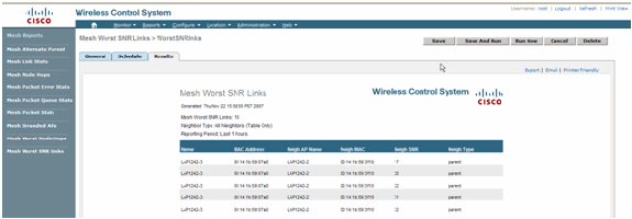
The worst SNR links
Noise problems might occur at different times and noise might increase at different rates or last for different lengths of time. The next figure provides the ability to create report for both Radio a and b/g as well as selective interfaces. The report lists the 10 worst SNR links by default. You can choose from 5 to 50 worst links. The report can be generated for the last 1 hour, last 6 hours, last day, last 2 days, and up to 7 days. The data is polled every 10 minutes by default. The data is kept in database for maximum seven days. The neighbor Type selection criteria can be All Neighbors, Parent/Children only.

Worst Node Hops
This report lists the10 worst hops APs by default. If the APs are too many hops away, the links could be very weak. The user can isolate the APs which have many hops away from Root AP and take appropriate action. You can choose to change this Number of Nodes criteria between 5 and 50. The Report Type filter criteria in this figure can be Table Only or Table and Graph:

This figure shows the result for the last report:

Security Statistics
The Indoor Mesh Security statistics are displayed on the AP detail page under the Bridging info section. An entry in the Indoor MeshNodeSecurity Statistic table is created when a child indoor mesh node associates or authenticates with a parent Indoor Mesh node. Entries are removed when the Indoor Mesh node disassociates from the Controller.
Link Test
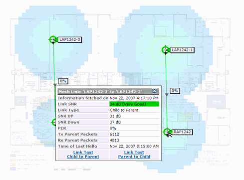
The AP-to-AP link test is supported on the WCS. One can select any two APs and invoke a link test between the two.
If those APs are RF neighbors, then the link test may have a result. The result is shown in a dialog on the map itself without a complete page refresh. The dialog can be disposed of easily.
However, if those 2 APs are not RF neighbors, then WCS does not try to figure out a path between the 2 APs in order to do a combine multiple link test.
When the mouse is moved over the arrow on the link between the two nodes, this window appears:
Node-to-Node Link Test
The Link Test tool is an on-demand tool to verify the link quality between any two APs. In WCS, this feature is added on the AP detail page.
On the AP detail page, under the Indoor Mesh Link tab where links are listed next to it, there is a link to perform the link test.
The Controller CLI Link Test tool has the optional input parameters: Packet size, Total Link test packets, duration of test, and Data Link rate. The link test has default values for these optional parameters. The MAC addresses for the Nodes are the only mandatory input parameters.
The Link Test tool tests strength, the packet sent, and packet received between nodes. The link for Link Test is displayed on the AP detail report. When you click the link, there is a pop-up screen showing the Link Test results. The Link Test will only be applicable to Parent–Child and among neighbors.
The Link Test output generates Packets sent, Packets received, Error packets (buckets for diff reasons), SNR, Noise Floor, and RSSI.
The Lnk Test provides these details on the GUI at a minimum:
-
Link Test Packets Sent
-
Link Test Packets Received
-
Signal Strength in dBm
-
Signal to Noise Ratio
On-Demand AP Neighbor Links
This is a new feature in the WCS Map. You can click on a Mesh AP and a pop-up window with detail info appears. You can then click View Mesh Neighbors, which fetches the neighbor information for the selected AP and displays a table with all the neighbors for the selected indoor mesh AP.
The View Mesh Neighbor Link displays all the neighbors for the highlighted AP. This snapshot shows all the neighbors, the Type of the neighbors, and the SNR value.
Ping Test
The Ping Test is an on-demand tool used to ping between the Controller and AP. The Ping Test tool is available in both the AP detail page and in MAP. Click the Run Ping Test link in either the AP detail page or from the MAP AP info to initiate the ping from the Controller to the current AP.
Conclusion
Enterprise Mesh (that is, indoor mesh) is an extension of Cisco wireless coverage to places where wired ethernet cannot provide connectivity. Flexibility and manageability of a wireless network is accomplished with Enterprise mesh.
Most of the features wired APs provide is provided by the indoor mesh topology. Enterprise mesh can also co-exist with the wired APs on the same controller.
Related Information
Revision History
| Revision | Publish Date | Comments |
|---|---|---|
1.0 |
01-Dec-2013 |
Initial Release |


 Feedback