Configure a RADIUS Server and WLC for Dynamic VLAN Assignment
Available Languages
Contents
Introduction
This document introduces the concept of dynamic VLAN assignment. The document describes how to configure the wireless LAN controller (WLC) and a RADIUS server to assign wireless LAN (WLAN) clients into a specific VLAN dynamically.
Prerequisites
Requirements
Ensure that you meet these requirements before you attempt this configuration:
-
Have basic knowledge of the WLC and Lightweight Access Points (LAPs)
-
Have functional knowledge of the AAA server
-
Have thorough knowledge of wireless networks and wireless security issues
-
Have basic knowledge of Lightweight AP Protocol (LWAPP)
Components Used
The information in this document is based on these software and hardware versions:
-
Cisco 4400 WLC that runs firmware release 5.2
-
Cisco 1130 Series LAP
-
Cisco 802.11a/b/g Wireless Client Adapter that runs firmware release 4.4
-
Cisco Aironet Desktop Utility (ADU) that runs version 4.4
-
CiscoSecure Access Control Server (ACS) that runs version 4.1
-
Cisco 2950 series switch
The information in this document was created from the devices in a specific lab environment. All of the devices used in this document started with a cleared (default) configuration. If your network is live, make sure that you understand the potential impact of any command.
Conventions
Refer to Cisco Technical Tips Conventions for more information on document conventions.
Dynamic VLAN Assignment with RADIUS Server
In most WLAN systems, each WLAN has a static policy that applies to all clients associated with a Service Set Identifier (SSID), or WLAN in the controller terminology. Although powerful, this method has limitations because it requires clients to associate with different SSIDs in order to inherit different QoS and security policies.
However, the Cisco WLAN solution supports identity networking. This allows the network to advertise a single SSID, but allows specific users to inherit different QoS or security policies based on the user credential.
Dynamic VLAN assignment is one such feature that places a wireless user into a specific VLAN based on the credentials supplied by the user. This task of assigning users to a specific VLAN is handled by a RADIUS authentication server, such as CiscoSecure ACS. This can be used, for example, to allow the wireless host to remain on the same VLAN as it moves within a campus network.
Therefore, when a client attempts to associate to a LAP registered with a controller, the LAP passes the credentials of the user to the RADIUS server for validation. Once the authentication is successful, the RADIUS server passes certain Internet Engineering Task Force (IETF) attributes to the user. These RADIUS attributes decide the VLAN ID that should be assigned to the wireless client. The SSID (WLAN, in terms of WLC) of the client does not matter because the user is always assigned to this predetermined VLAN ID.
The RADIUS user attributes used for the VLAN ID assignment are:
-
IETF 64 (Tunnel Type)—Set this to VLAN.
-
IETF 65 (Tunnel Medium Type)—Set this to 802
-
IETF 81 (Tunnel Private Group ID)—Set this to VLAN ID.
The VLAN ID is 12-bits, and takes a value between 1 and 4094, inclusive. Because the Tunnel-Private-Group-ID is of type string, as defined in RFC2868 ![]() for use with IEEE 802.1X, the VLAN ID integer value is encoded as a string. When these tunnel attributes are sent, it is necessary to fill in the Tag field.
for use with IEEE 802.1X, the VLAN ID integer value is encoded as a string. When these tunnel attributes are sent, it is necessary to fill in the Tag field.
As noted in RFC2868 ![]() , section 3.1: The Tag field is one octet in length and is intended to provide a means of grouping attributes in the same packet which refer to the same tunnel. Valid values for this field are 0x01 through 0x1F, inclusive. If the Tag field is unused, it must be zero (0x00). Refer to RFC 2868
, section 3.1: The Tag field is one octet in length and is intended to provide a means of grouping attributes in the same packet which refer to the same tunnel. Valid values for this field are 0x01 through 0x1F, inclusive. If the Tag field is unused, it must be zero (0x00). Refer to RFC 2868 ![]() for more information on all RADIUS attributes.
for more information on all RADIUS attributes.
Configure
In this section, you are presented with the information to configure the features described in this document.
Network Diagram
This document uses this network setup:
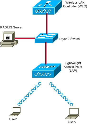
These are the configuration details of the components used in this diagram:
-
The IP address of the ACS (RADIUS) server is 172.16.1.1.
-
The Management Interface address of the WLC is 172.16.1.30.
-
The AP-Manager Interface address of the WLC is 172.16.1.31.
-
The DHCP server address 172.16.1.1 is used to assign IP addresses to the LWAPP. The internal DHCP server on the controller is used to assign the IP address to wireless clients.
-
VLAN10 and VLAN11 are used throughout this configuration. The user1 is configured to be placed into the VLAN10 and user2 is configured to be placed into VLAN11 by the RADIUS server.
Note: This document only shows all the configuration information related to user1. Complete the same procedure explained in this document for the user2.
-
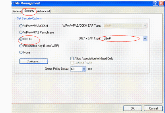
This document uses 802.1x with LEAP as the security mechanism.
Note: Cisco recommends that you use advanced authentication methods, such as EAP-FAST and EAP-TLS authentication, in order to secure the WLAN. This document uses LEAP only for simplicity.
Configuration
Prior to the configuration, this document assumes that the LAP is already registered with the WLC. Refer to Wireless LAN Controller and Lightweight Access Point Basic Configuration Example for more information. Refer to Lightweight AP (LAP) Registration to a Wireless LAN Controller (WLC) for information about the registration procedure involved.
Configuration Steps
This configuration is separated into three categories:
RADIUS Server Configuration
This configuration requires these steps:
Configure the AAA Client for the WLC on the RADIUS Server
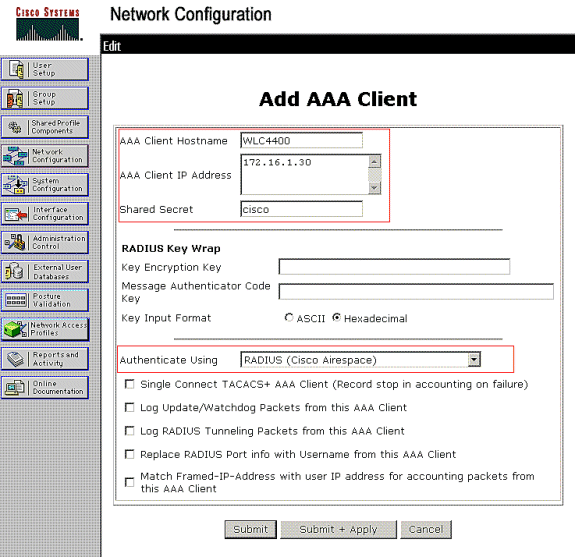
This procedure explains how to add the WLC as a AAA client on the RADIUS server so that the WLC can pass the user credentials to the RADIUS server.
Complete these steps:
-
From the ACS GUI, click Network Configuration.
-
Click the Add Entry section under the AAA Clients field.
-
Enter the AAA Client IP Address and Key.
The IP address should be the Management Interface IP address of the WLC.
Make sure that the key you enter is the same as the one configured on the WLC under the Security window. This is the secret key used for communication between the AAA client (WLC) and the RADIUS server.
-
Choose RADIUS (Cisco Airespace) from the Authenticate Using field for the authentication type.
Configure the Users and the RADIUS (IETF) Attributes Used for Dynamic VLAN Assignment on the RADIUS Server
This procedure explains how to configure the users in the RADIUS server and the RADIUS (IETF) attributes used to assign VLAN IDs to these users.
Complete these steps:
-
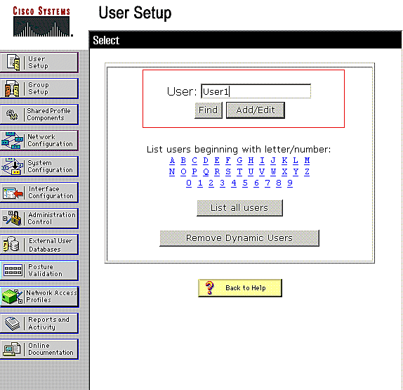
From the ACS GUI, click User Setup.
-
In the User Setup window, enter a username in the User field and click Add/Edit.
-
On the Edit page, enter the necessary user information as shown here:
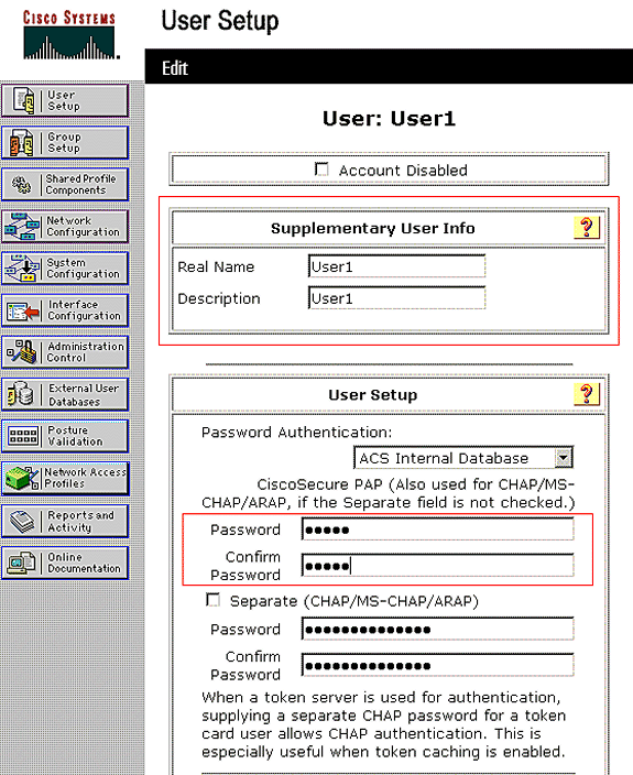
In this diagram, notice that the password you provide under the User Setup section should be the same as the one provided at the client side during the user authentication.
-
Scroll down the Edit page and find the IETF RADIUS Attributes field.
-
In the IETF RADIUS Attributes field, check the check boxes next to the three Tunnel attributes and configure the attribute values as shown here:
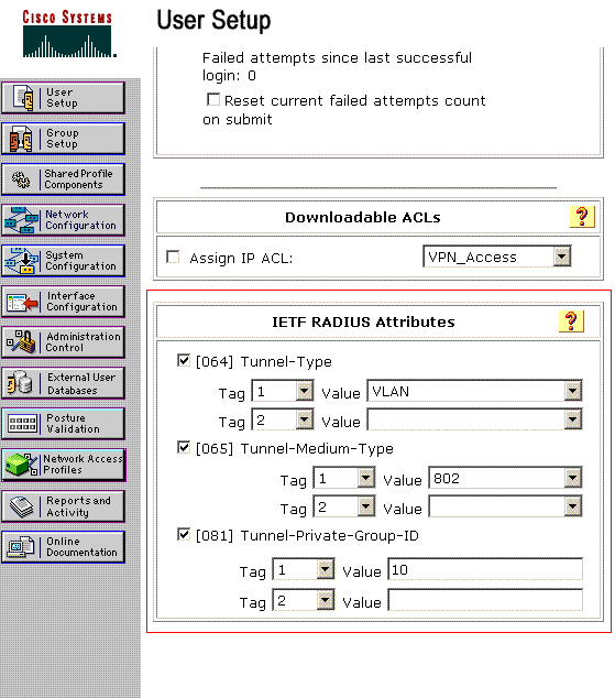
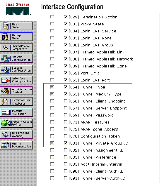
Note: In the initial configuration of the ACS server, IETF RADIUS attributes might not be displayed.
-
Choose Interface Configuration > RADIUS (IETF) in order to enable IETF attributes in the user configuration window.
-
Then, check the check boxes for attributes 64, 65, and 81 in the User and Group columns.
Note: In order for the RADIUS server to dynamically assign the client to a specific VLAN, it is required that the VLAN-ID configured under the IETF 81 (Tunnel-Private-Group-ID) field of the RADIUS server exist on the WLC.
-
Check the Per User TACACS+/RADIUS attribute check box under Interface Configuration > Advanced Options in order to enable the RADIUS server for per user configurations.
-
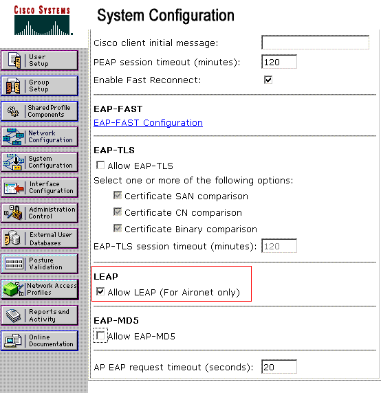
Also, because LEAP is used as the Authentication protocol, ensure that LEAP is enabled in the System Configuration window of the RADIUS server as shown here:
-
Configure the ACS with Cisco Airespace VSA Attributes for Dynamic VLAN Assignment
In the latest ACS versions, you can also configure the Cisco Airespace [VSA (Vendor-Specific)] attribute to assign a successfully authenticated user with a VLAN interface name (not the VLAN ID) as per the user configuration on the ACS. In order to accomplish this, perform the steps in this section.
Note: This section uses ACS 4.1 version to configure the Cisco Airespace VSA attribute.
Configure the ACS Group with Cisco Airespace VSA Attribute Option
Complete these steps:
-
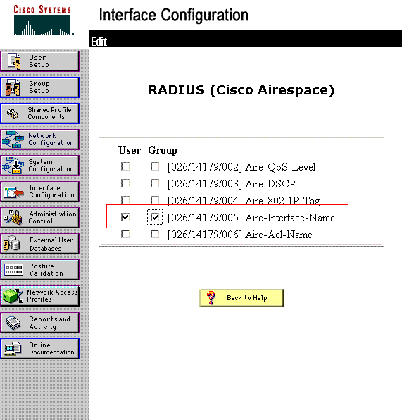
From the ACS 4.1 GUI, click Interface Configuration from the navigation bar. Then, select RADIUS (Cisco Airespace) from the Interface Configuration page in order to configure the Cisco Airespace attribute option.
-
From the RADIUS (Cisco Airespace) window, check the User check box (Group check box if needed) next to Aire-Interface-Name in order to display it on the User Edit page. Then, click Submit.
-
Go to the user1's Edit page.
-
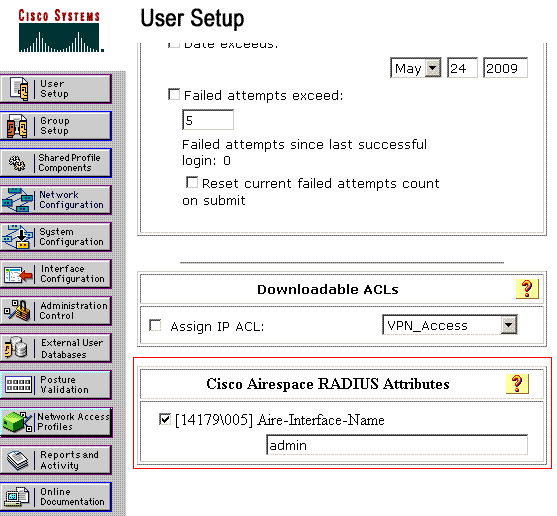
From the User Edit page, scroll down to the Cisco Airespace RADIUS Attributes section. Check the check box next to the Aire-Interface-Name attribute and specify the name of the dynamic interface to be assigned upon successful user authentication.
This example assigns the user to admin VLAN.
-
Click Submit.
Configure the Switch for Multiple VLANs
In order to allow multiple VLANs through the switch, you need to issue these commands to configure the switch port connected to the controller:
-
Switch(config-if)#switchport mode trunk
-
Switch(config-if)#switchport trunk encapsulation dot1q
Note: By default, most of the switches allow all VLANs created on that switch via the trunk port.
These commands vary for a Catalyst operating system (CatOS) switch.
If a wired network is connected to the switch, then this same configuration can be applied to the switch port that connects to the wired network. This enables the communication between the same VLANs in the wired and wireless network.
Note: This document does not discuss inter-VLAN communication. This is beyond the scope of this document. You must understand that for inter-VLAN routing, a Layer 3 switch or an external router with proper VLAN and trunking configurations is needed. There are several documents that explain inter-VLAN routing configuration.
WLC Configuration
This configuration requires these steps:
Configure the WLC with the Details of the Authentication Server
It is necessary to configure the WLC so it can communicate with the RADIUS server to authenticate the clients, and also for any other transactions.
Complete these steps:
-
From the controller GUI, click Security.
-
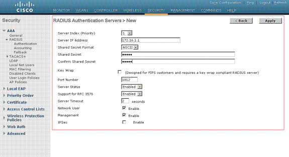
Enter the IP address of the RADIUS server and the Shared Secret key used between the RADIUS server and the WLC.
This Shared Secret key should be the same as the one configured in the RADIUS server under Network Configuration > AAA Clients > Add Entry. Here is an example window from the WLC:
Configure the Dynamic Interfaces (VLANs)
This procedure explains how to configure dynamic interfaces on the WLC. As explained earlier in this document, the VLAN ID specified under the Tunnel-Private-Group ID attribute of the RADIUS server must also exist in the WLC.
In the example, the user1 is specified with the Tunnel-Private-Group ID of 10 (VLAN =10) on the RADIUS server. See the IETF RADIUS Attributes section of the user1 User Setup window.
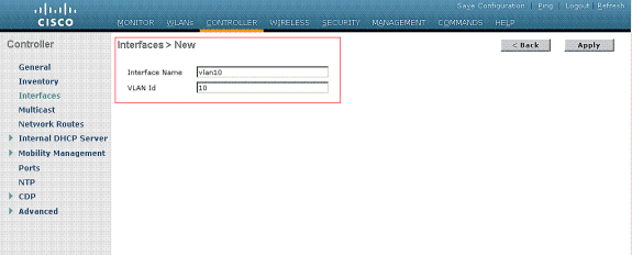
You can see the same dynamic interface (VLAN=10) configured in the WLC in this example. From the controller GUI, under the Controller > Interfaces window, the dynamic interface is configured.
-
Click Apply on this window.
This takes you to the Edit window of this dynamic interface (VLAN 10 here).
-
Enter the IP Address and default Gateway of this dynamic interface.
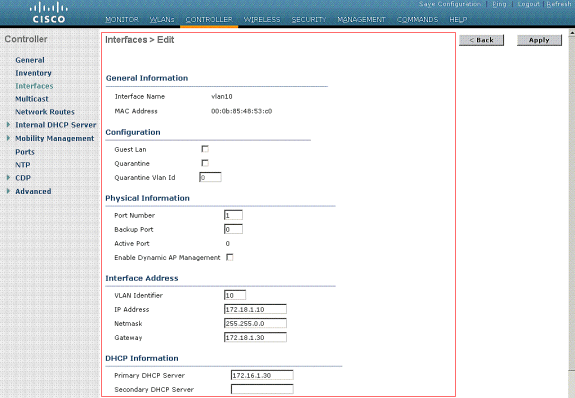
Note: Because this document uses an internal DHCP server on the controller, the primary DHCP server field of this window points to the Management Interface of the WLC itself. You can also use an external DHCP server, a router, or the RADIUS server itself as a DHCP server to the wireless clients. In such cases, the primary DHCP server field points to the IP address of that device used as the DHCP server. Refer to your DHCP server documentation for more information.
-
Click Apply.
Now you are configured with a dynamic interface in your WLC. Similarly, you can configure several dynamic interfaces in your WLC. However, remember that the same VLAN ID must also exist in the RADIUS server for that particular VLAN to be assigned to the client.
Configure the WLANs (SSID)
This procedure explains how to configure the WLANs in the WLC.
Complete these steps:
-
From the controller GUI, choose WLANs > New in order to create a new WLAN.
The New WLANs window is displayed.
-
Enter the WLAN ID and WLAN SSID information.
You can enter any name to be the WLAN SSID. This example uses VLAN10 as the WLAN SSID.

-
Click Apply in order to go to the Edit window of the WLAN SSID10.
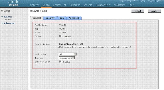
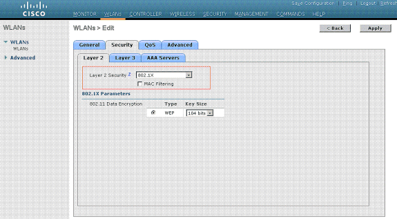
Normally, in a wireless LAN controller, each WLAN is mapped to a specific VLAN (SSID) so that a particular user that belongs to that WLAN is put into the specific VLAN mapped. This mapping is normally done under the Interface Name field of the WLAN SSID window.
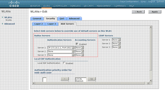
In the example provided, it is the job of the RADIUS server to assign a wireless client to a specific VLAN upon successful authentication. The WLANs need not be mapped to a specific dynamic interface on the WLC. Or, even though the WLAN to dynamic interface mapping is done on the WLC, the RADIUS server overrides this mapping and assigns the user that comes through that WLAN to the VLAN specified under the user Tunnel-Group-Private-ID field in the RADIUS server.
-
Check the Allow AAA Override check box in order to override the WLC configurations by the RADIUS server.
-
Enable the Allow AAA Override in the controller for each WLAN (SSID) configured.
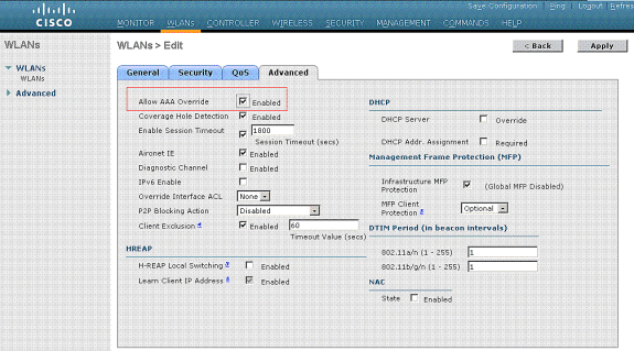
When AAA Override is enabled, and a client has AAA and controller WLAN authentication parameters that conflict, client authentication is performed by the AAA (RADIUS) server. As part of this authentication, the operating system moves clients to a VLAN returned by the AAA server. This is predefined in the controller interface configuration.
For instance, if the corporate WLAN primarily uses a Management Interface assigned to VLAN 2, and if the AAA Override returns a redirect to VLAN 100, the operating system redirects all client transmissions to VLAN 100 even if the physical port to which VLAN 100 is assigned. When AAA Override is disabled, all client authentication defaults to the controller authentication parameter settings, and authentication is only performed by the AAA server if the controller WLAN does not contain any client-specific authentication parameters.
Wireless Client Utility Configuration
This document uses ADU as the client utility for the configuration of the user profiles. This configuration also uses LEAP as the authentication protocol. Configure the ADU as shown in the example in this section.
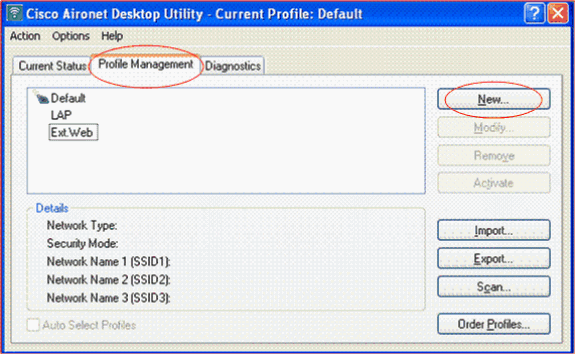
From the ADU Menu bar, choose Profile Management > New in order to create a new profile.
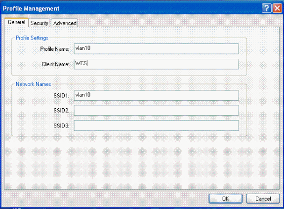
The example client is configured to be a part of SSID VLAN10. These diagrams show how to configure a user profile on a client:
Verify
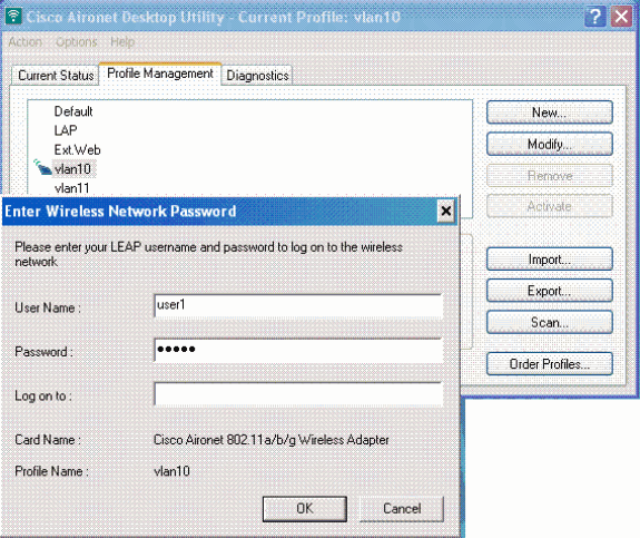
Activate the user profile you have configured in the ADU. Based on the configuration, you are prompted for a username and password. You can also instruct the ADU to use the Windows username and password for authentication. There are a number of options from which the client can receive authentication. You can configure these options under the Security > Configure tab of the user profile you have created.
In the previous example, notice that user1 is assigned to the VLAN10 as specified in the RADIUS server.
This example uses this username and password from the client side to receive authentication and to be assigned to a VLAN by the RADIUS server:
-
User Name = user1
-
Password = user1
This example shows how the SSID VLAN10 is prompted for the username and password. The username and password are entered in this example:
Once the authentication and the corresponding validation is successful, you receive success as the status message.
Then, you need to verify that your client is assigned to the proper VLAN as per the RADIUS attributes sent. Complete these steps in order to accomplish this:
-
From the controller GUI, choose Wireless > AP.
-
Click Clients, which appears on the left corner of the Access Points (APs) window.
The client statistics are displayed.

-
Click Details in order to identify the complete details of the client, such as IP address, the VLAN to which it is assigned, and so forth.
This example displays these details of the client, user1:
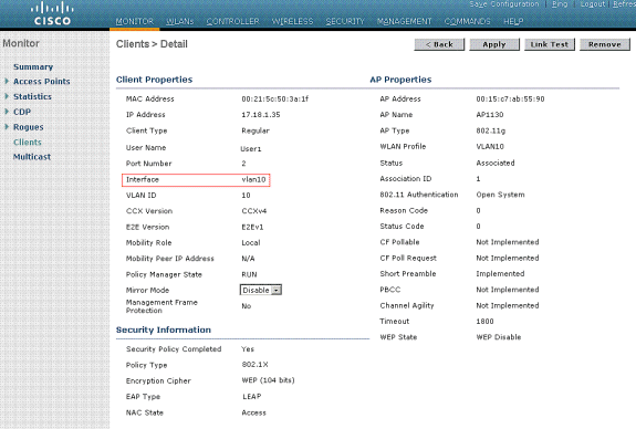
From this window, you can observe that this client is assigned to VLAN10 as per the RADIUS attributes configured on the RADIUS server.
Note: If the dynamic VLAN assignment is based on the Cisco Airespace VSA Attribute setting, the Interface name will display it as admin as per this example on the client details page.
Use this section to confirm that your configuration works properly.
-
debug aaa events enable—This command can be used to ensure successful transfer of the RADIUS attributes to the client via the controller. This portion of the debug output ensures a successful transmission of RADIUS attributes:
Fri Jan 20 02:25:08 2006: 00:40:96:ac:e6:57 processing avps[0]:
attribute 64, vendorId 0, valueLen 4
Fri Jan 20 02:25:08 2006: 00:40:96:ac:e6:57 processing avps[1]:
attribute 65, vendorId 0, valueLen 4
Fri Jan 20 02:25:08 2006: 00:40:96:ac:e6:57 processing avps[2]:
attribute 81, vendorId 0, valueLen 3
Fri Jan 20 02:25:08 2006: 00:40:96:ac:e6:57 processing avps[3]:
attribute 79, vendorId 0, valueLen 32
Fri Jan 20 02:25:08 2006: 00:40:96:ac:e6:57 Received EAP Attribute
(code=2, length=32,id=0) for mobile 00:40:96:ac:e6:57
Fri Jan 20 02:25:08 2006: 00000000: 02 00 00 20 11 01 00 18
4a 27 65 69 6d e4 05 f5
........J'eim...00000010: d0 98 0c cb 1a 0c 8a 3c
........44 a9 da 6c 36 94 0a f3  <D..l6...
Fri Jan 20 02:25:08 2006: 00:40:96:ac:e6:57 processing avps[4]:
attribute 1, vendorId 9, valueLen 16
Fri Jan 20 02:25:08 2006: 00:40:96:ac:e6:57 processing avps[5]:
attribute 25, vendorId 0, valueLen 28
Fri Jan 20 02:25:08 2006: 00:40:96:ac:e6:57 processing avps[6]:
attribute 80, vendorId 0, valueLen 16
Fri Jan 20 02:25:08 2006: 00:40:96:ac:e6:57 Tunnel-Type 16777229
should be 13 for STA 00:40:96:ac:e6:57
Fri Jan 20 02:25:08 2006: 00:40:96:ac:e6:57 Tunnel-Medium-Type 16777222
should be 6 for STA 00:40:96:ac:e6:57
Fri Jan 20 02:30:00 2006: 00:40:96:ac:e6:57 Station 00:40:96:ac:e6:57
setting dot1x reauth timeout = 1800
-
These commands can also be useful:
-
debug dot1x aaa enable
-
debug aaa packets enable
-
Troubleshoot
There is currently no specific troubleshooting information available for this configuration.
Note: Dynamic VLAN assignment does not work for web authentication from a WLC.
Related Information
Revision History
| Revision | Publish Date | Comments |
|---|---|---|
1.0 |
01-Dec-2013 |
Initial Release |


 Feedback