Client VPN over Wireless LAN with WLC Configuration Example
Available Languages
Contents
Introduction
This document introduces the concept of Virtual Private Network (VPN) in a wireless environment. The document explains the configurations involved in the deployment of a VPN tunnel between a wireless client and a VPN server through a Wireless LAN Controller (WLC).
Prerequisites
Requirements
Ensure that you meet these requirements before you attempt this configuration:
-
Knowledge of WLCs and how to configure the WLC basic parameters
-
Knowledge of Wi-Fi Protected Access (WPA) concepts
-
Basic knowledge of VPN and its types
-
Knowledge of IPsec
-
Basic knowledge of the available encryption, authentication and hashing algorithms
Components Used
The information in this document is based on these software and hardware versions:
-
Cisco 2006 WLC that runs version 4.0.179.8
-
Cisco 1000 Series Lightweight Access Point (LAP)
-
Cisco 3640 that runs Cisco IOS® Software Release 12.4(8)
-
Cisco VPN Client version 4.8
Note: This document uses a 3640 router as a VPN server. In order to support more advanced security features, you can also use a dedicated VPN server.
Note: In order for a router to act as a VPN server, it needs to run a feature set that supports basic IPsec.
The information in this document was created from the devices in a specific lab environment. All of the devices used in this document started with a cleared (default) configuration. If your network is live, make sure that you understand the potential impact of any command.
Conventions
Refer to Cisco Technical Tips Conventions for more information on document conventions.
Background Information
A VPN is a private data network that is used to securely transmit the data within a private network through the public telecommunication infrastructure such as the Internet. This VPN maintains data privacy through the use of a tunneling protocol and security procedures.
Remote Access VPN
A remote access VPN configuration is used to allow VPN software clients such as mobile users to securely access centralized network resources that reside behind a VPN server. In Cisco terminologies, these VPN servers and clients are also called the Cisco Easy VPN server and the Cisco Easy VPN Remote device.
A Cisco Easy VPN Remote device can be Cisco IOS routers, Cisco PIX Security Appliances, Cisco VPN 3002 Hardware Clients and the Cisco VPN Client. They are used to receive security policies upon a VPN tunnel connection from a Cisco Easy VPN Server. This minimizes configuration requirements at the remote location. The Cisco VPN Client is a software client that can be installed on PCs, laptops, and so forth.
A Cisco Easy VPN Server can be Cisco IOS routers, Cisco PIX Security Appliances, and Cisco VPN 3000 Concentrators.
This document uses Cisco VPN Client software that runs on a laptop as the VPN Client and Cisco 3640 IOS Router as the VPN server. The document uses the IPsec standard to establish a VPN tunnel between a client and a server.
IPsec
IPsec is a framework of open standards developed by the Internet Engineering Task Force (IETF). IPsec provides security for the transmission of sensitive information over unprotected networks such as the Internet.
IPsec provides network data encryption at the IP packet level, which offers a robust security solution that is standards-based. The main task of IPsec is to allow the exchange of private information over an insecure connection. IPsec uses encryption to protect information from interception or eavesdropping. However, to use encryption efficiently, both parties should share a secret that is used for both the encryption and decryption of the information.
IPsec operates in two phases to allow the confidential exchange of a shared secret:
-
Phase 1—Handles the negotiation of security parameters required to establish a secure channel between two IPsec peers. Phase 1 is generally implemented through the Internet Key Exchange (IKE) protocol. If the remote IPsec peer cannot perform IKE, you can use manual configuration with pre-shared keys to complete Phase 1.
-
Phase 2—Uses the secure tunnel established in Phase 1 to exchange the security parameters required to actually transmit user data. The secure tunnels used in both phases of IPsec are based on security associations (SAs) used at each IPsec end point. SAs describe the security parameters, such as the type of authentication and encryption that both end points agree to use.
The security parameters exchanged in Phase 2 are used to create an IPsec tunnel which in turn is used for data transfer between the VPN Client and the server.
Refer to Configuring IPsec for more information about IPsec and its configuration.
Once a VPN tunnel is established between the VPN Client and the server, the security policies defined at the VPN server are sent to the client. This minimizes configuration requirements at the client side.
Note: Use the Command Lookup Tool (registered customers only) to find more information on the commands used in this document.
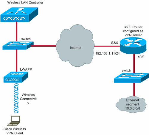
Network Diagram
This document uses these configurations:
-
Management interface IP address of the WLC—172.16.1.10/16
-
AP-manager interface IP address of the WLC—172.16.1.11/16
-
Default gateway—172.16.1.20/16
Note: In a live network, this default gateway should point to the incoming interface of the immediate router that connects the WLC to the rest of network and/or to the Internet.
-
IP address of the VPN server s3/0—192.168.1.11/24
Note: This IP address should point to the interface which terminates the VPN tunnel at the VPN server side. In this example, s3/0 is the interface that terminates the VPN tunnel at the VPN server.
-
The LAN segment at the VPN server uses the IP address range of 10.0.0.0/8.
Configure
In a WLAN centralized architecture, in order to allow a wireless VPN Client such as a laptop to establish a VPN tunnel with a VPN server, it is necessary that the client gets associated with a Lightweight Access Point (LAP) which in turn needs to be registered with a WLC. This document has the LAP as already registered with the WLC using the local subnet broadcast discovery process explained in Lightweight AP (LAP) Registration to a Wireless LAN Controller (WLC).
The next step is to configure the WLC for VPN.
VPN Termination and Pass-through
With Cisco 4000 Series WLCs earlier than version 4, a feature called IPsec VPN termination (IPsec support) is supported. This feature enables these controllers to terminate VPN Client sessions directly on the controller. In summary, this feature enables the controller itself to act as a VPN server. But this requires a separate VPN termination hardware module to be installed in the controller.
This IPsec VPN support is not available in:
-
Cisco 2000 Series WLC
-
Any WLCs that run version 4.0 or later
Therefore, the only VPN feature supported in versions later than 4.0 is VPN Pass-through. This feature is also supported in the Cisco 2000 Series WLC.
VPN Pass-through is a feature which allows a client to establish a tunnel only with a specific VPN server. So, if you need to securely access the configured VPN server as well as another VPN server or the Internet, this is not possible with VPN Pass-through enabled on the controller. Under such requirements, you need to disable VPN Pass-through. However, the WLC can be configured to act as passthrough in order to reach multiple VPN gateways when an appropriate ACL is created and applied to the corresponding WLAN. So, under such scenarios where you want to reach multiple VPN gateways for redundancy, disable VPN passthrough and create an ACL that allows access to the VPN gateways and apply the ACL to the WLAN.
Configure the WLC for VPN Pass-through
Complete these steps in order to configure VPN Pass-through.
-
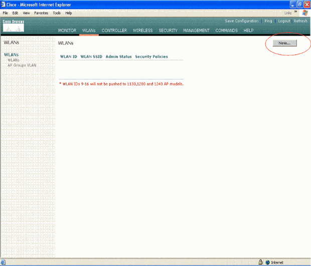
From the WLC GUI, click WLAN in order to go to the WLANs page.
-
Click New in order to create a new WLAN.
-
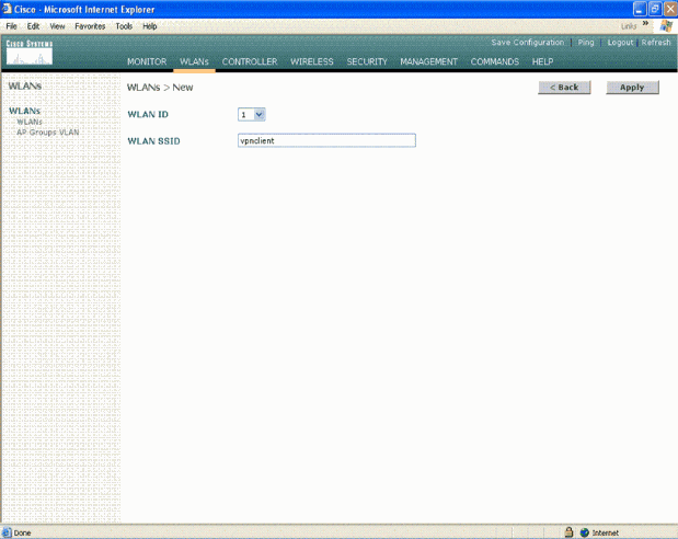
The WLAN SSID is named as vpnclient in this example. Click Apply.
-
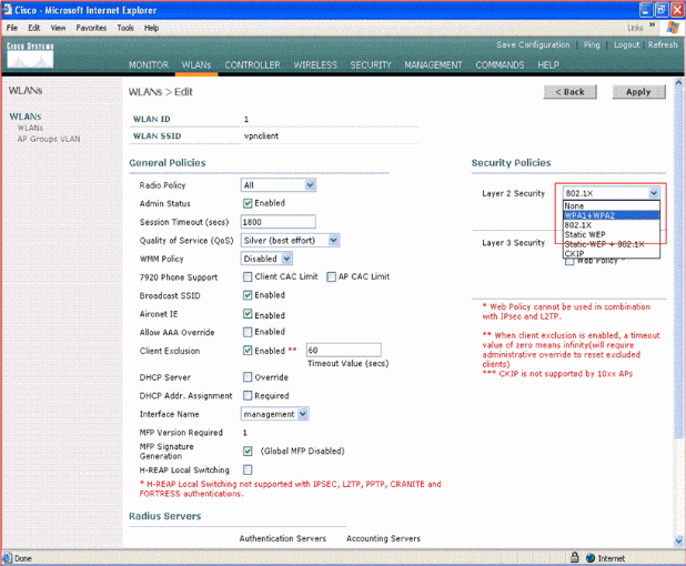
Configure the vpnclient SSID with Layer 2 security. This is optional.
This example uses WPA1+WPA2 as the security type.
-
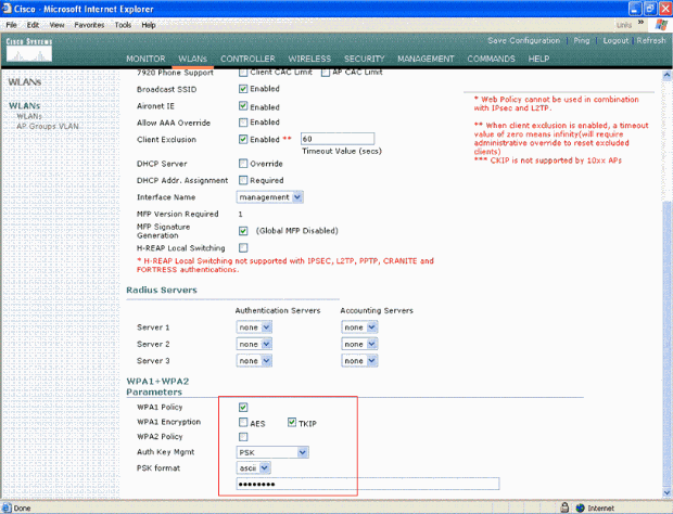
Configure the WPA policy and the Authentication Key management type to be used.
This example uses Pre-Shared Key (PSK) for authentication key management. Once PSK is selected, select ASCII as the PSK format and type the PSK value. This value should be the same in the SSID configuration of the wireless client in order for the clients that belong to this SSID to associate with this WLAN.
-
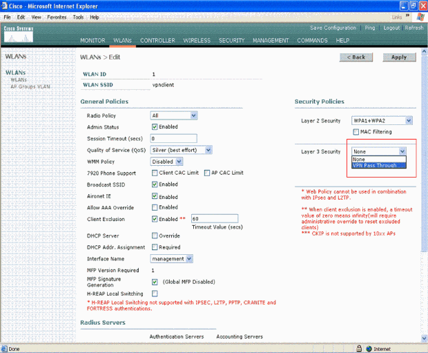
Select VPN Pass-through as the Layer 3 Security. Here is the example.
-
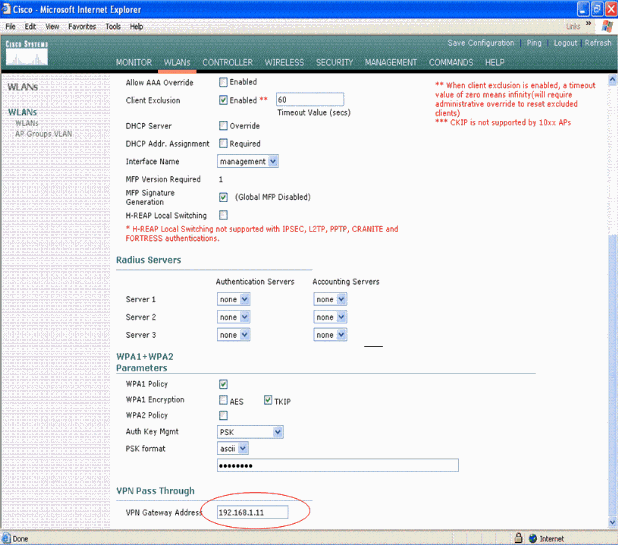
Once VPN Pass-through is selected as the Layer 3 security, add the VPN Gateway Address as this example shows.
This gateway address should be the IP address of the interface that terminates the VPN tunnel at the server side. In this example, the IP address of the s3/0 interface (192.168.1.11/24) at the VPN server is the gateway address to be configured.
-
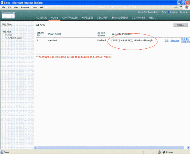
Click Apply. The WLAN called vpnclient is now configured for VPN Pass-through.
VPN Server Configuration
This configuration shows the Cisco 3640 Router as the VPN server.
Note: For simplicity, this configuration uses static routing to maintain IP reachability between the end points. You can use any dynamic routing protocol such as Routing Information Protocol (RIP), Open Shortest Path First (OSPF), and so forth to maintain reachability.
Note: The tunnel is not established if there is no IP reachability between the client and the server.
Note: This document assumes that the user is aware of how to enable dynamic routing in the network.
| Cisco 3640 Router |
|---|
vpnrouter#show running-config

Building configuration...

Current configuration : 1623 bytes
!
version 12.4
service timestamps debug datetime msec
service timestamps log datetime msec
no service password-encryption
!
hostname vpnrouter
!
boot-start-marker
boot-end-marker
!
!
aaa new-model
!
!
aaa authorization network employee local
!
aaa session-id common
!
resource policy
!
memory-size iomem 10
!
!
ip cef
no ip domain lookup
!
!
!
!
!
!
!
!
!
!
!
!
!
!
!
!
!
!
crypto isakmp policy 1


!--- Create an Internet Security Association and Key Management !--- Protocol (ISAKMP) policy for Phase 1 negotiation.

hash md5

!--- Choose the hash algorithm to be md5.

authentication pre-share

!--- The authentication method selected is pre-shared.

group 2

!--- With the group command, you can declare what size modulus to !--- use for Diffie-Hellman calculation. Group 1 is 768 bits long, !--- and group 2 is 1024 bits long.


crypto isakmp client configuration group employee
 key cisco123
 pool mypool

!

!--- Create the Phase 2 policy for actual data encryption.

crypto ipsec transform-set myset esp-3des esp-md5-hmac

!--- Create a dynamic map and apply the transform set that was created. !--- Set reverse-route for the VPN server.

crypto dynamic-map mymap 10
 set transform-set myset
 reverse-route
!
crypto map clientmap isakmp authorization list employee


!--- Create the crypto map.


crypto map clientmap client configuration address
crypto map clientmap 10 ipsec-isakmp dynamic mymap

!

!--- Apply the employee group list that was created earlier.


!
!
!
!
interface Ethernet0/0
 ip address 10.0.0.20 255.0.0.0
 half-duplex
!
interface Serial3/0
 ip address 192.168.1.11 255.255.255.0
 clock rate 64000
 no fair-queue
 crypto map clientmap


!--- Apply the crypto map to the interface.

!
interface Serial3/1
 no ip address
 shutdown
!
interface Serial3/2
 no ip address
 shutdown
!
interface Serial3/3
 no ip address
 shutdown
!
interface Serial3/4
 no ip address
 shutdown
!
interface Serial3/5
 no ip address
 shutdown
!
interface Serial3/6
 no ip address
 shutdown
!
interface Serial3/7
 no ip address
 shutdown
ip local pool mypool 10.0.0.50 10.0.0.60

!--- Configure the Dynamic Host Configuration Protocol !--- (DHCP) pool which assigns the tunnel !--- IP address to the wireless client. !--- This tunnel IP address is different from the IP address !--- assigned locally at the wireless client (either statically or dynamically).


ip http server
no ip http secure-server
!
ip route 172.16.0.0 255.255.0.0 192.168.1.10
!
!
!
!
control-plane
!
!
!
!
!
!
!
!
!
!
line con 0
line aux 0
line vty 0 4
!
!
end


ip subnet-zero . . .
!
end |
Note: This example uses only the group authentication. It does not use individual user authentication.
VPN Client Configuration
A software VPN Client can be downloaded from the Cisco.com Software Center.
Note: Some Cisco software requires you to login with a CCO username and password.
Complete these steps in order to configure the VPN Client.
-
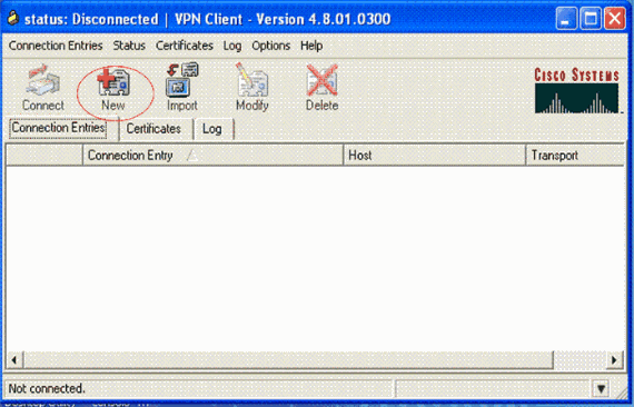
Form your wireless client (laptop), choose Start > Programs > Cisco Systems VPN Client > VPN Client in order to access the VPN Client. This is the default location where the VPN Client is installed.
-
Click New in order to launch the Create New VPN Connection Entry window.
-
Enter the name of the Connection Entry along with a description. This example usesvpn.
The Description field is optional. Enter the IP address of the VPN server in the Host box. Then enter the VPN Group Name and Password and click Save.
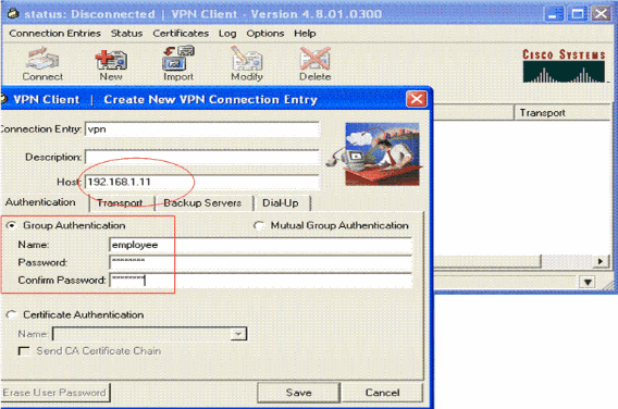
Note: The Group Name and Password configured here should be the same as the one configured in the VPN server. This example uses the Name employee and Password cisco123.
Verify
In order to verify this configuration, configure the SSID vpnclient in the wireless client with the same security parameters configured in the WLC and associate the client to this WLAN. There are several documents that explain how to configure a wireless client with a new profile.
Once the wireless client is associated, go to the VPN Client and click on the connection that you have configured. Then click Connect from the VPN Client main window.
You can see the Phase 1 and Phase 2 security parameters negotiated between the client and the server.
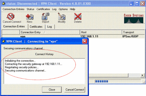
Note: In order to establish this VPN tunnel, the VPN Client and the server should have IP reachability between them. If the VPN Client is not able to contact the security gateway (VPN server), then the tunnel is not established and an alert box is displayed at the client side with this message:
Reason 412: The remote peer is no longer responding
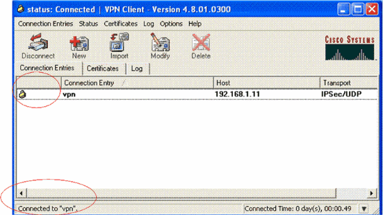
In order to ensure that a VPN tunnel is properly established between the client and server, you can find a lock icon that is created next to the established VPN Client. The status bar also indicates Connected to "vpn". Here is an example.
Also, ensure that you are able to successfully transmit data to the LAN segment at the server side from the VPN Client and vice-versa. From the VPN Client main menu, choose Status > Statistics. There you can find the statistics of the encrypted and decrypted packets that are passed through the tunnel.
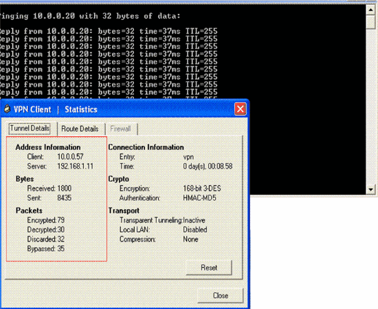
In this screenshot, you can see the client address as 10.0.0.57. This is the address that the VPN server assigns to the client from its locally configured pool after successful Phase 1 negotiation. Once the tunnel is established, the VPN server automatically adds a route to this assigned DHCP IP address in its route table.
You can also see the number of encrypted packets increasing while the data is transferred from the client to the server and the number of decrypted packets increasing during a reverse data transfer.
Note: Since the WLC is configured for VPN Pass-through, it allows the client to access only the segment connected with the VPN gateway (here, it is 192.168.1.11 VPN server) configured for Pass-through. This filters all other traffic.
You can verify this by configuring another VPN server with the same configuration and configure a new connection entry for this VPN server at the VPN Client. Now, when you try to establish a tunnel with this VPN server, it is not successful. This is because the WLC filters this traffic and allows a tunnel only to the VPN gateway address configured for VPN Pass-through.
You can also verify the configuration from the CLI of the VPN server.
The Output Interpreter Tool (registered customers only) (OIT) supports certain show commands. Use the OIT to view an analysis of show command output.
Note: Refer to Important Information on Debug Commands before you use debug commands.
These show commands used in the VPN server might also be useful to help you verify the tunnel status.
-
The show crypto session command is used to verify the tunnel status. Here is an example output of this command.
Crypto session current status Interface: Serial3/0 Session status: UP-ACTIVE Peer: 172.16.1.20 port 500 IKE SA: local 192.168.1.11/500 remote 172.16.1.20/500 Active IPSEC FLOW: permit ip 0.0.0.0/0.0.0.0 host 10.0.0.58 Active SAs: 2, origin: dynamic crypto map -
The show crypto isakmp policy is used to view the configured Phase 1 parameters.
Troubleshoot
The debug and show commands explained in the Verify section can also be used to troubleshoot.
-
debug crypto isakmp
-
debug crypto ipsec
-
show crypto session
-
The debug crypto isakmp command at the VPN server displays the entire Phase 1 negotiation process between the client and the server. Here is an example of a successful Phase 1 negotiation.
-------------------------------------------------------------------
 ------------------------------------------------------------
---------------------------------------------------------------
*Aug 28 10:37:29.515: ISAKMP:(0:0:N/A:0):Checking ISAKMP transform 14
   against priority 1 policy
*Aug 28 10:37:29.515: ISAKMP:      encryption DES-CBC
*Aug 28 10:37:29.515: ISAKMP:      hash MD5
*Aug 28 10:37:29.515: ISAKMP:      default group 2
*Aug 28 10:37:29.515: ISAKMP:      auth pre-share
*Aug 28 10:37:29.515: ISAKMP:      life type in seconds
*Aug 28 10:37:29.515: ISAKMP:      life duration (VPI) of  0x0 0x20 0xC4 0x9B
*Aug 28 10:37:29.515: ISAKMP:(0:0:N/A:0):atts are acceptable. Next payload is 0
*Aug 28
*Aug 28 10:37:29.955: ISAKMP:(0:15:SW:1):SA authentication status:
	authenticated
*Aug 28 10:37:29.955: ISAKMP:(0:15:SW:1): Process initial contact,
  bring down existing phase 1 and 2 SA's with local 192.168.1.11
  remote 172.16.1.20 remote port 500
*Aug 28 10:37:29.955: ISAKMP:(0:15:SW:1):returning IP addr to
  the address pool: 10.0.0.57
*Aug 28 10:37:29.955: ISAKMP (0:134217743): returning address 10.0.0.57 to pool
*Aug 28 10:37:29.959: ISAKMP:(0:14:SW:1):received initial contact, deleting SA
*Aug 28 10:37:29.959: ISAKMP:(0:14:SW:1):peer does not do pade
  1583442981 to QM_IDLE
*Aug 28 10:37:29.963: ISAKMP:(0:15:SW:1):Sending NOTIFY
  RESPONDER_LIFETIME protocol 1
	spi 1689265296, message ID = 1583442981
*Aug 28 10:37:29.967: ISAKMP:(0:15:SW:1): sending packet to
  172.16.1.20 my_port 500 peer_port 500 (R) QM_IDLE
*Aug 28 10:37:29.967: ISAKMP:(0:15:SW:1):purging node 1583442981
*Aug 28 10:37:29.967: ISAKMP: Sending phase 1 responder lifetime 86400

*Aug 28 10:37:29.967: ISAKMP:(0:15:SW:1):Input = IKE_MESG_FROM_PEER, IKE_AM_EXCH
*Aug 28 10:37:29.967: ISAKMP:(0:15:SW:1):Old State = IKE_R_AM2
  New State = IKE_P1_COMPLETE
-
The debug crypto ipsec command at the VPN server displays the successful Phase 1 IPsec negotiation and creation of the VPN tunnel. Here is an example:
-----------------------------------------------------------------------
 --------------------------------------------------------------------
------------------------------------------------------------------------
*Aug 28 10:40:04.267: IPSEC(key_engine): got a queue event with 1 kei messages
*Aug 28 10:40:04.271: IPSEC(spi_response): getting spi 2235082775 for SA
	from 192.168.1.11 to 172.16.1.20 for prot 3
*Aug 28 10:40:04.279: IPSEC(key_engine): got a queue event with 2 kei messages
*Aug 28 10:40:04.279: IPSEC(initialize_sas): ,
  (key eng. msg.) INBOUND local= 192.168.1.11, remote= 172.16.1.20,
    local_proxy= 0.0.0.0/0.0.0.0/0/0 (type=4),
    remote_proxy= 10.0.0.58/0.0.0.0/0/0 (type=1),
    protocol= ESP, transform= esp-3des esp-md5-hmac  (Tunnel),
    lifedur= 2147483s and 0kb,
    spi= 0x8538A817(2235082775), conn_id= 0, keysize= 0, flags= 0x2
*Aug 28 10:40:04.279: IPSEC(initialize_sas): ,
  (key eng. msg.) OUTBOUND local= 192.168.1.11, remote= 172.16.1.20,
    local_proxy= 0.0.0.0/0.0.0.0/0/0 (type=4),
    remote_proxy= 10.0.0.58/0.0.0.0/0/0 (type=1),
    protocol= ESP, transform= esp-3des esp-md5-hmac  (Tunnel),
    lifedur= 2147483s and 0kb,
    spi= 0xFFC80936(4291299638), conn_id= 0, keysize= 0, flags= 0xA
*Aug 28 10:40:04.283: IPSEC(rte_mgr): VPN Route Event create routes for
  peer or rekeying for peer 172.16.1.20
*Aug 28 10:40:04.283: IPSEC(rte_mgr): VPN Route Refcount 1 Serial3/0
*Aug 28 10:40:04.283: IPSEC(rte_mgr): VPN Route Added
  10.0.0.58 255.255.255.255 via 172.16.1.20 in IP DEFAULT TABLE with tag 0
*Aug 28 10:40:04.283: IPSec: Flow_switching Allocated flow for sibling 8000001F
*Aug 28 10:40:04.283: IPSEC(policy_db_add_ident): src 0.0.0.0, dest 10.0.0.58,
  dest_port 0

*Aug 28 10:40:04.287: IPSEC(create_sa): sa created,
  (sa) sa_dest= 192.168.1.11, sa_proto= 50,
    sa_spi= 0x8538A817(2235082775),
    sa_trans= esp-3des esp-md5-hmac , sa_conn_id= 2002
*Aug 28 10:40:04.287: IPSEC(create_sa): sa created,
  (sa) sa_dest= 172.16.1.20, sa_proto= 50,
    sa_spi= 0xFFC80936(4291299638),
    sa_trans= esp-3des esp-md5-hmac , sa_conn_id= 2001
Related Information
- An Introduction to IP Security (IPsec) Encryption
- IPsec Negotiation/IKE Protocol Support Page
- Configuring IPsec Network Security
- Cisco Easy VPN Q&A
- Cisco Wireless LAN Controller Configuration Guide, Release 4.0
- ACLs on Wireless LAN Controller Configuration Example
- Wireless LAN Controller (WLC) FAQ
- Wireless Support Page
- Technical Support & Documentation - Cisco Systems
Revision History
| Revision | Publish Date | Comments |
|---|---|---|
1.0 |
31-Jan-2007 |
Initial Release |


 Feedback