Configure and Synch NTP for Unified Wireless Network Devices
Available Languages
Contents
Introduction
This document explains how to configure NTP in wireless LAN devices, such as Wireless LAN Controller (WLC), Wireless Control System (WCS), and Wireless Location Appliance.
In a Unified Wireless Network, it is essential that the WLCs, Location Appliance, and WCS use NTP in order to have a common clock source. This document explains how to synchronize local time on the different devices of a Unified Wireless Network. This is particularly important for Daylight Savings Time (DST) changes.
Prerequisites
Requirements
There are no specific requirements for this document.
Components Used
This document is not restricted to specific software and hardware versions.
Conventions
Refer to Cisco Technical Tips Conventions for more information on document conventions.
Daylight Savings Time
With the recent change in the start and ending date of DST in the United States, the controller will display an incorrect local time (1 hour off if DST is enabled) in the logs between these times:
-
2:00 a.m. on the second Sunday in March until 2 a.m. on the first Sunday in April (between the start of the new DST and the start of the old DST time)
-
2:00 a.m. on the last Sunday in October until 2 a.m. on the first Sunday in November (between the end of the old DST time and the end of the new DST time)
Note: After the start of the old DST on the first Sunday in April until the end of the old DST on the last Sunday in October, the controller will indicate the correct local time if no changes are made.
This does not affect the WLC's internal time that it uses to communicate with the WCS and Location Appliance, but does affect the local time displayed in the log. This situation makes it more difficult to compare events in the WCS log with the events in the controller's message or trap log.
The WLCs, Location Appliance, and WCS must all be within 15 minutes internal time (not local time [internal time with offset]) or the location server will not display or track clients. Instead, this error message is received in the location server log:
3/28/07 17:46:59 ERROR[location] Failed to create heat map for MAC:
xx:xx:xx:xx:xx:xx Reason: Failed as the RSSI list is empty after time pruning
The Location Appliance only has enough real time storage for the last 15 minutes of stored data. Remember that the Location Appliance is for real time tracking of clients while the WCS archives the data over longer periods of time. WCS can track clients, but updates only every few minutes. Real time cannot track clients.
If the clocks are off between the devices, there is no client data after the Location Appliance removes the ones outside of the specified time interval in the request. In fact, if the location server receives data from the controller with the internal time stamp more than 15 minutes outside its internal time, it tosses the data into the bit bucket.
You should turn on NTP on the WLCs, WCS, and Location Appliance in order to automatically synchronize the internal time to UTC. You can also manually enter the times and make sure that all are set at the same time. Cisco recommends that you use NTP.
NTP Configuration
This section provides the configuration steps in each of the Unified Wireless Network devices that must be completed in order to configure NTP.
Note: Use the Command Lookup Tool (registered customers only) to obtain more information on the commands used in this section.
Set Up NTP on the Location Appliance
Complete these steps in order to set up NTP on the Location Appliance, using the Linux resources that are already in the box:
-
Stop the Location Appliance service.
/etc/rc.d/init.d/locserverd stop

[root@loc-server root]#/etc/rc.d/init.d/locserverd stop
Shutting down locserverd: Request server shutdown now...
Waiting for server...2 secs
Waiting for server...4 secs
Server shutdown complete.
-
Set the time zone.
cp /usr/share/zoneinfo/<your country>/<your timezone> /etc/localtime

[root@loc-server root]#cp /usr/share/zoneinfo/US/Eastern /etc/localtime
cp: overwrite `/etc/localtime'? y
[root@loc-server root]#
-
Add your NTP server in /etc/ntp.conf using a text editor. This example shows the vi editor.
[root@loc-server root]#vi /etc/ntp.conf
-
/ puts you in search mode. Enter server and press Enter in order to go to that location.
-
i puts you in insert mode. Position the cursor to point to a location under the existing server line. Press Enter in order to add a new line.
-
Enter server, then press Tab and enter the IP address of the NTP server.
In this example, the IP address of the NTP server is 172.22.1.216.
-
Press Esc in order to get out of insert mode.
-
Enter :wq and press Enter in order to write changes and quit the vi editor.
The file looks like this output. The line to change is the one that starts with server.
# --- GENERAL CONFIGURATION ---
#
# Undisciplined Local Clock. This is a fake driver intended for
# backup and when no outside source of synchronized time is
# available. The default stratum is usually 3, but in this case
# we elect to use stratum 0. Since the server line does not have
# the prefer keyword, this driver is never used for synchronization,
# unless no other other synchronization source is available. In case
# the local host is controlled by some external source, such as an
# external oscillator or another protocol, the prefer keyword would
# cause the local host to disregard all other synchronization sources,
# unless the kernel modifications are in use and declare an
# unsynchronized condition.
#
server 172.22.1.216     # local clock
-
-
Make sure that there is no time zone defined in /etc/sysconfig/clock. This example shows the use of the more command.
[root@loc-server etc]#more /etc/sysconfig/clock
# ZONE="UTC"
UTC=true
ARC=false
Notice that the line that starts with ZONE is commented out. If it is not, use an editor, such as vi, to add the # symbol at the beginning of the ZONE command in order to make the command be only a comment.
-
Turn on the config checker in order to make sure things are not misconfigured. Use the chkconfig ntpd on command.
[root@loc-server etc]#chkconfig ntpd on
	[root@loc-server etc]#
-
Restart the network in order to bring in the new time zone configuration.
/etc/rc.d/init.d/network restart

[root@loc-server root]#/etc/rc.d/init.d/network restart
Shutting down interface eth0:  [  OK  ]
Shutting down loopback interface:  [  OK  ]
Setting network parameters:  [  OK  ]
Bringing up loopback interface:  ip_tables: (C) 2000-2002 Netfilter
  core team [OK]
Bringing up interface eth0:  ip_tables: (C) 2000-2002 Netfilter
  core team [OK]
[root@loc-server root]#
-
Restart the NTP daemon in order to bring in the new settings.
/etc/rc.d/init.d/ntpd restart

[root@loc-server root]#/etc/rc.d/init.d/ntpd restart
Shutting down ntpd: [  OK  ]
Starting ntpd: [  OK  ]
[root@loc-server root]#
-
Initially seed the NTP process with the time.
ntpdate -u <NTP server IP address defined earlier>

[root@loc-server etc]#ntpdate -u 172.22.1.216
28 Mar 17:35:27 ntpdate[2947]: step time server 172.22.1.216 offset
  1.766436 sec
-
Restart the Location Appliance service.
/etc/rc.d/init.d/locserverd start

[root@loc-server etc]#/etc/rc.d/init.d/locserverd start
Starting locserverd:
[root@loc-server etc]#
Set Up NTP on the WCS
The WCS relies on Windows or Linux for the correct time. The WCS checks the Windows Operating System or the Linux Operating System once every 24 hours for the system time. Therefore, it does not immediately know about system time changes unless you stop and restart the WCS server. Right-click on the clock and select Adjust Date/Time. Use an NTP time source to set the clock and manually set the offset for your time zone. This is typically already set.
Set Up NTP on the WLCs
There are several ways to configure the WLCs for NTP. You can configure each WLC directly from the WLC GUI interface or CLI, or you can configure each WLCs from the WCS. Also, you can configure a set of WLCs from the WCS templates.
Note: If your network has a WCS, Cisco highly recommends to configure the WLC from the WCS templates.
Complete these steps in order to configure the NTP server on a single WLC directly:
-
On the controller, issue the show time CLI command in order to verify the time of the WLC and offset.
This output shows that there is no NTP server configured on this WLC.
Note: The time shows a ficticious date on Jan 2001.
(Cisco Controller) >show time Time............................................. Mon Jan 1 03:14:02 2001 Timezone delta................................... 0:0 Daylight savings................................. disabled NTP Servers NTP Polling Interval......................... 3600 Index NTP Server ------- -------------------------------- -
Issue the config time ntp server <index> <server address> command in order to set up the NTP server on the WLC using CLI.
(Cisco Controller) >config time ntp server 1 172.16.1.216
-
Issue the show time CLI command again in order to verify the time of the WLC and offset is set up right after the NTP server has been configured.
Note: In this output, the Time shows the correct time and the NTP server is shown with the IP address 172.22.1.216.
(Cisco Controller) >show time

Time............................................. Wed Mar 28 17:35:51 2007

Timezone delta................................... 0:0
Daylight savings................................. disabled

NTP Servers
    NTP Polling Interval.........................     86400

     Index              NTP Server
    -------  --------------------------------
       1     172.22.1.216
Complete these steps in order to set up NTP on the WLCs using controller templates on the WCS:
-
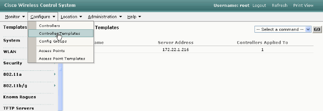
From the GUI of the WCS, choose Configure > Controller Templates from the top menu.
Note: Usually the default template screen is the Network Protocol Template. If not, then from the left side menu choose System > Network Time Protocol.
-
In the new window, choose Add Template from the Select a Command pull down menu on the top right side of the page and click GO.

-
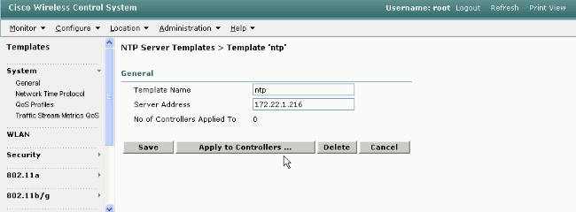
In the new window, enter the Template Name and the Server Address (of the NTP server).
In this example, the template name is ntp and the IP address of the NTP server is 172.22.1.216.
-
Click Save and then Apply to Controllers.
-
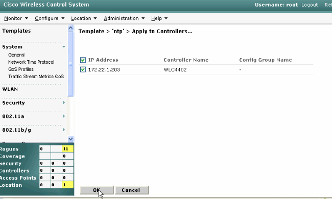
Select the controllers to which you want to apply the template configuration and click OK.
In this example, there is only one WLC.
Instructions for Synching the WCS, Location Appliance, and WLCs
This section provides information on how to synchronize time between all three products with NTP.
Synchronization Procedure
Complete these steps in order to synchronize the Location Appliance with WCS:
-
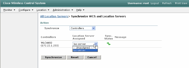
Choose Location > Synchronize Servers from the GUI of the WCS.

-
Choose Controllers from the Synchronize pull down menu.
-
In the same window, choose loc-server from the Location Server Assigned pull down menu and click Synchronize.
When you use the WCS Controller Templates in order to set up the NTP server on the WLCs, the time between WCS and WLCs are synchronized automatically because they obtain their time from the NTP server.
Verify
Use this section to confirm that your configuration works properly.
The Output Interpreter Tool (registered customers only) (OIT) supports certain show commands. Use the OIT to view an analysis of show command output.
-
time—Shows the actual time of the server where the WCS is installed.
-
date—Shows the actual date of the server where the WCS is installed.
-
date—Shows the date and time of the Location Appliance.
-
show time—Shows the date and time of the WLCs. Also shows the information of the NTP server when the WLC obtains its time from NTP.
This is how you can verify the time settings on the WCS, Location Appliance, and WLCs:
-
WCS—Look at the clock of the Windows or Linux Server, or look at the output of the date and time commands:
C:\Documents and Settings\Administrator>date
The current date is: Wed 03/28/2007
C:\Documents and Settings\Administrator>time
The current time is: 17:37:15.67
-
Location Appliance—Output of the date command:
[root@loc-server root]#date
Wed Mar 28 17:36:54 UTC 2007
-
WLCs—Output of the show time command:
(Cisco Controller) >show time

Time............................................. Wed Mar 28 17:37:59 2007

Timezone delta................................... 0:0
Daylight savings................................. disabled

NTP Servers
    NTP Polling Interval.........................     86400

     Index              NTP Server
    -------  --------------------------------
       1     172.22.1.216
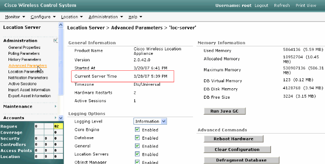
Another method you can use to obtain the time and date of the Location Appliance is to gather the information from the WCS. In order to perform this, from the WCS GUI select Location --> Location Servers, then click on Administration -->Advance Parameters.
Troubleshoot
This section provides information you can use to troubleshoot your configuration.
If time is not synchronized between the WCS, Location Appliance, and the WLCs, the logs provide information that is hard to relate between devices.
Troubleshooting Commands
Note: Refer to Important Information on Debug Commands before you use debug commands.
Note: These debug commands on the WLCs are helpful in order to detect problems with the NTP configuration:
-
debug ntp low enable—Allows to see information about ntp messages and how the NTP server is reached. It also contains the number of accepts, rejects, and flushes.
-
debug ntp detail enable—Provides detailed information on the ntp server NTP polling cycles, the correction on the time, and the new date and time.
-
debug ntp packet enable—Provides the ntp packets that are exchanged from the WLC and the NTP server. These packets are in hexadecimal.
These are the outputs of the debug ntp low enable, debug ntp detail enable, and debug ntp packet enable commands:
(Cisco Controller) >debug ntp ?

detail         Configures debug of detailed NTP messages.
low            Configures debug of NTP messages.
packet         Configures debug of NTP packets.
(Cisco Controller) >config time ntp server 1 172.22.1.216


(Cisco Controller) >Mon Jan  1 03:15:30 2001: Initiating time sequence
Mon Jan  1 03:15:30 2001: Fetching time from:
Mon Jan  1 03:15:30 2001:  172.22.1.216
Mon Jan  1 03:15:30 2001:

Started=3187307730.428852 2001 Jan 01 03:15:30.428
Looking for the socket addresses
NTP Polling cycle: accepts=0, count=5, attempts=1, retriesPerHost=6.
Outgoing packet on NTP Server on socket 0:
sta=0 ver=3 mod=3 str=15 pol=8 dis=0.000000 ref=0.000000
ori=0.000000 rec=0.000000
tra=3187307730.429039 cur=3187307730.429039
00000000: 1b 0f 08 00 00 00 00 00  00 00 00 00 00 00 00 00  ................
00000010: 00 00 00 00 00 00 00 00  00 00 00 00 00 00 00 00  ................
00000020: 00 00 00 00 00 00 00 00  bd fa 74 d2 6d d5 80 00  ..........t.m...
Flushing outstanding packets
Flushed 0 packets totalling 0 bytes
Packet of length 48 sent to 172.22.1.216 UDPport=123
Packet of length 48 received from 172.22.1.216 UDPport=123
Incoming packet on socket 0:
00000000: 1c 08 08 ee 00 00 00 00  00 00 00 02 7f 7f 07 01  ................
00000010: c9 b5 3c 58 6f a9 8b 4e  bd fa 74 d2 6d d5 80 00  ..<Xo..N..t.m...
00000020: c9 b5 3c 63 87 39 7b 87  c9 b5 3c 63 87 3a fb 56  ..<c.9{...<c.:.V
sta=0 ver=3 mod=4 str=8 pol=8 dis=0.000031 ref=3384097880.436181
ori=3187307730.429039 rec=3384097891.528221
tra=3384097891.528244 cur=3187307730.447082
Offset=196790161.090172+/-0.018020 disp=0.000031
best=196790161.090172+/-0.018020
accepts=1 rejects=0 flushes=0
Correction: 196790161.090172 +/- 0.018020 disp=0.000031
Setting clock to 2007 Mar 28 19:11:31.537 - 196790161.090 +/- 0.018 secs
Times: old=(978318930,447965) new=(1175109091,538136) adjust=(196790161,090171)
time changed by 196790161.090 secs to 2007 Mar 28 19:11:31.580 +/- 0.000+0.018
Wed Mar 28 19:11:31 2007: Stopped normally

(Cisco Controller) >
If the NTP server cannot be reached, you see an output similar to this on the WLC after you turn on the debugs already mentioned. In this scenario, the output shows that it tries to reach an NTP server located at 172.22.1.215, which does not exist.
(Cisco Controller) >config time ntp server 1 172.22.1.215


(Cisco Controller) >Mon Jan  1 03:15:17 2001: Initiating time sequence
Mon Jan  1 03:15:17 2001: Fetching time from:
Mon Jan  1 03:15:17 2001:  172.22.1.215
Mon Jan  1 03:15:17 2001:

Started=3187307717.666379 2001 Jan 01 03:15:17.666
Looking for the socket addresses
NTP Polling cycle: accepts=0, count=5, attempts=1, retriesPerHost=6.
Outgoing packet on NTP Server on socket 0:
sta=0 ver=3 mod=3 str=15 pol=8 dis=0.000000 ref=0.000000
ori=0.000000 rec=0.000000
tra=3187307717.666567 cur=3187307717.666567
00000000: 1b 0f 08 00 00 00 00 00  00 00 00 00 00 00 00 00  ................
00000010: 00 00 00 00 00 00 00 00  00 00 00 00 00 00 00 00  ................
00000020: 00 00 00 00 00 00 00 00  bd fa 74 c5 aa a4 20 00  ..........t.....
Flushing outstanding packets
Flushed 0 packets totalling 0 bytes
Packet of length 48 sent to 172.22.1.215 UDPport=123
NTP Polling cycle: accepts=0, count=5, attempts=2, retriesPerHost=6.
Outgoing packet on NTP Server on socket 0:
sta=0 ver=3 mod=3 str=15 pol=8 dis=0.000000 ref=0.000000
ori=0.000000 rec=0.000000
tra=3187307719.660125 cur=3187307719.660125
00000000: 1b 0f 08 00 00 00 00 00  00 00 00 00 00 00 00 00  ................
00000010: 00 00 00 00 00 00 00 00  00 00 00 00 00 00 00 00  ................
00000020: 00 00 00 00 00 00 00 00  bd fa 74 c7 a8 fd f0 00  ..........t.....
Flushing outstanding packets
Flushed 0 packets totalling 0 bytes
Packet of length 48 sent to 172.22.1.215 UDPport=123
NTP Polling cycle: accepts=0, count=5, attempts=3, retriesPerHost=6.
Outgoing packet on NTP Server on socket 0:
sta=0 ver=3 mod=3 str=15 pol=8 dis=0.000000 ref=0.000000
ori=0.000000 rec=0.000000
tra=3187307721.660105 cur=3187307721.660105
00000000: 1b 0f 08 00 00 00 00 00  00 00 00 00 00 00 00 00  ................
00000010: 00 00 00 00 00 00 00 00  00 00 00 00 00 00 00 00  ................
00000020: 00 00 00 00 00 00 00 00  bd fa 74 c9 a8 fc a8 00  ..........t.....
Flushing outstanding packets
Flushed 0 packets totalling 0 bytes
Packet of length 48 sent to 172.22.1.215 UDPport=123
NTP Polling cycle: accepts=0, count=5, attempts=4, retriesPerHost=6.
Outgoing packet on NTP Server on socket 0:
sta=0 ver=3 mod=3 str=15 pol=8 dis=0.000000 ref=0.000000
ori=0.000000 rec=0.000000
tra=3187307723.660174 cur=3187307723.660174
00000000: 1b 0f 08 00 00 00 00 00  00 00 00 00 00 00 00 00  ................
00000010: 00 00 00 00 00 00 00 00  00 00 00 00 00 00 00 00  ................
00000020: 00 00 00 00 00 00 00 00  bd fa 74 cb a9 01 28 00  ..........t...(.
Flushing outstanding packets
Flushed 0 packets totalling 0 bytes
Packet of length 48 sent to 172.22.1.215 UDPport=123
NTP Polling cycle: accepts=0, count=5, attempts=5, retriesPerHost=6.
Outgoing packet on NTP Server on socket 0:
sta=0 ver=3 mod=3 str=15 pol=8 dis=0.000000 ref=0.000000
ori=0.000000 rec=0.000000
tra=3187307725.660105 cur=3187307725.660105
00000000: 1b 0f 08 00 00 00 00 00  00 00 00 00 00 00 00 00  ................
00000010: 00 00 00 00 00 00 00 00  00 00 00 00 00 00 00 00  ................
00000020: 00 00 00 00 00 00 00 00  bd fa 74 cd a8 fc a8 00  ..........t.....
Flushing outstanding packets
Flushed 0 packets totalling 0 bytes
Packet of length 48 sent to 172.22.1.215 UDPport=123
NTP Polling cycle: accepts=0, count=5, attempts=6, retriesPerHost=6.
Outgoing packet on NTP Server on socket 0:
sta=0 ver=3 mod=3 str=15 pol=8 dis=0.000000 ref=0.000000
ori=0.000000 rec=0.000000
tra=3187307727.660105 cur=3187307727.660105
00000000: 1b 0f 08 00 00 00 00 00  00 00 00 00 00 00 00 00  ................
00000010: 00 00 00 00 00 00 00 00  00 00 00 00 00 00 00 00  ................
00000020: 00 00 00 00 00 00 00 00  bd fa 74 cf a8 fc a8 00  ..........t.....
Flushing outstanding packets
Flushed 0 packets totalling 0 bytes
Packet of length 48 sent to 172.22.1.215 UDPport=123
Offset=196790161.090172+/-0.018020 disp=0.000031
best=196790161.090172+/-0.018020
accepts=0 rejects=6 flushes=0
no acceptable packets received
Mon Jan  1 03:15:29 2001: Stopped normally
As seen from this output, there are six attempts to reach the NTP server at 172.22.1.215. After these attempts, the WLC stops trying to reach the NTP server and continues to have the local time that was configured manually.
When you use CheckPoint as NTP server, the controller is unable to interpret the received NTP updates. Therefore, this error is seen and time is not synchronized on the controller:
[ERROR] sntp_main.c 270: : too many bad or lost packets
[ERROR] sntp_main.c 270: : no acceptable packets received
[WARNING] sntp_main.c 455: incomprehensible NTP packet rejected on socket 0
This is because of Cisco bug ID CSCsh50252 (registered customers only) . This issue is seen only with CheckPoint NTP server. The workaround is to use a different NTP server or to configure time statically on the controller.
Related Information
- Wireless Location Appliance FAQ
- Wireless Control System (WCS) Troubleshoot FAQ
- Wireless Control System Troubleshooting
- Network Time Protocol: Best Practices White Paper
- FN - 62646 - US Daylight Savings Time Policy Change Effective March 2007 - for Wireless Products
- U.S. Daylight Saving Time (DST) Changes for 2007 - Wireless
- Daylight Saving Time For Cisco Wireless Networking Platforms
- Technical Support & Documentation - Cisco Systems
Revision History
| Revision | Publish Date | Comments |
|---|---|---|
1.0 |
30-Mar-2007 |
Initial Release |
Contact Cisco
- Open a Support Case

- (Requires a Cisco Service Contract)


 Feedback