Introduction
This document describes how to interconnect the Switch Processor Input/Output (SPIO) console of a Cisco Aggregation Services Router (ASR) 5000 Series to a Cisco Terminal Server (TS).
Note: This document is only relevant for the ASR5000. The ASR5500 has a standard Cisco console pinout. Official documentation is provided in the Connecting to the Serial Console Port section of the Cisco ASR 5000 Installation Guide.
The console uses an RS232 serial communications port to provide local management access to the CLI. A 9-pin-to-RJ45 console cable is supplied with each SPIO card. This cable can be used in order to connect to a PC or another terminal device that has a standard 9-pin serial interface. However, things become more complex when you must connect the SPIO console interface to a Cisco (or third-party) TS.
Prerequisites
Requirements
There are no specific requirements for this document.
Components Used
This document is not retricted to specific software and hardware versions.
The information in this document was created from the devices in a specific lab environment. All of the devices used in this document started with a cleared (default) configuration. If your network is live, make sure that you understand the potential impact of any command.
Pinout of SPIO
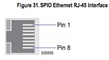
The SPIO has this pinout (taken from official documentation):
| RJ-45 Pin |
Signal |
Signal Type |
| 1 |
Clear to Send (CTS) |
Input - HW flow control |
| 2 |
Data set Ready (DSR) |
Input - RS232 control |
| 3 |
Receive Data (Rx) |
Input - Data Transfer |
| 4 |
Signal Ground (Grnd) |
N/A |
| 5 |
Ready to Send (RTS) |
Output - HW flow control |
| 6 |
Transmit Data (Tx) |
Output - Data transfer |
| 7 |
Data Carrier Detect (DCD) |
Input - RS232 control |
| 8 |
Data Terminal Ready (DTR) |
Output - RS232 control |
The pinout numbering is shown here (the image shows female RJ45 connector on SPIO):

Default Configuration of SPIO Console Port on ASR5000
This is the default SPIO port configuration on the ASR5000:
port rs232 24/3
 terminal speed 115200
 terminal stopbits 1
 terminal parity none
 terminal databits 8
 terminal flowcontrol hardware off
 terminal carrierdetect off
Here are some important points to note:
Connect to a Cisco TS That Contains Cab-Octal-Async
This pinout for the Octal cable (8 Port Breakout Cable) is taken from CAB-OCTAL-ASYNC Cable Pinouts:
| Rj-45 pin |
Signal name |
Signal Type |
| 8 |
RTS |
Output |
| 7 |
DTR |
Output |
| 6 |
TX Data |
Output |
| 5 |
TX ground |
N/A |
| 4 |
Rx ground |
N/A |
| 3 |
RX Data |
Input |
| 2 |
DSR |
Input |
| 1 |
CTS |
Input |
When you connect SPIO to the Octal cable of the TS, you have to make a null-modem cabling.
This means:
- RTS should be connected to CTS (and vice versa) - hardware flow control.
- DTR should be connected to DSR (and vice versa) - modem control.
- Tx should be connected to Rx (and vice versa).
- Ground should be connected to ground.
- DCD (on SPIO side) should not be connected (no corresponding signal on TS side).
Caution: Do NOT under any circumstances use a rolled RJ45 cable or a straight RJ45 cable to connect an SPIO directly with a Cisco TS. It will not work. The reason is that the ground voltage of the TS will be non-0. This can give very unpredictable results.
There are several options.
Configuration of Cisco TS
In order to match the default SPIO configuration, this configuration must be applied on a Cisco TS:
line 0/1/0 0/1/7
 exec-timeout 0 0
 no exec
 transport input all
 stopbits 1
 speed 115200
This configuration ensures that:
- RS232 control is disabled (so DTR is raised at all times).
- Hardware flow control is disabled (so the CTS is raised at all times).
Verify
There is currently no verification procedure available for this configuration.
Troubleshoot
There is currently no specific troubleshooting information available for this configuration.
