Configure High Availability SSO on Catalyst 9800 | Quick Start Guide
Available Languages
Download Options
Bias-Free Language
The documentation set for this product strives to use bias-free language. For the purposes of this documentation set, bias-free is defined as language that does not imply discrimination based on age, disability, gender, racial identity, ethnic identity, sexual orientation, socioeconomic status, and intersectionality. Exceptions may be present in the documentation due to language that is hardcoded in the user interfaces of the product software, language used based on RFP documentation, or language that is used by a referenced third-party product. Learn more about how Cisco is using Inclusive Language.
Contents
Introduction
This document describes how to configure High Availability stateful switchover (SSO) in a RP+RMI fashion, on a Catalyst 9800 WLC.
Prerequisites
Requirements
Cisco recommends you have knowledge of:
- Catalyst wireless 9800 configuration model
- Concepts of High Availability as covered in the HA SSO guide.
Components Used
The information in this document is based on these software and hardware versions:
- Catalyst 9800-CL (v. 17.12.3).
While HA SSO configuration can only require 3 of them, here 4 IP addresses from the same network as the wireless management interface (WMI) have been used to ease the access to the controller GUI.
The information in this document was created from the devices in a specific lab environment. All of the devices used in this document started with a cleared (default) configuration. If your network is live, ensure that you understand the potential impact of any command.
Background Information
The High availability SSO capability on the wireless controller allows the access point to establish a CAPWAP tunnel with the Active wireless controller and the Active wireless controller to share a mirror copy of the AP and client database with the Standby wireless controller. When switchovers occur (that is the Active controller fails and therefore the Standby takes the hand), joined APs do not go into the Discovery state and clients do not disconnect. There is only one CAPWAP tunnel maintained at a time between the APs and the wireless controller that is in an Active state.
The two units form a peer connection through a dedicated RP port (or a virtual interface for VMs) and both controllers share the same IP address on the management interface. The RP interface is used to synchronize bulk and incremental configuration at run-time and ensure the operational status of both controllers of the HA pair. In addition to that, when RMI + RP is used, both Standby and Active controllers have a redundancy management interface (RMI) to which are assigned IP addresses, namely used to ensure gateway reachability. The CAPWAP state of the Access Points that are in Run State is also synched from the active wireless controller to the Hot-Standby wireless controller which allows the Access Points to be state-fully switched over when the Active wireless controller fails. The APs do not go to the Discovery state when Active wireless controller fails, and Standby wireless controller takes over as the Active wireless controller to serve the network.
Configure
Network Diagram


Note: In orange is highlighted the temporary IP address assigned to the virtual interface GigabitEthernet 2 of the 9800-CL controller designated as WLC2. This IP address is temporarily defined as the WMI for WLC2 and allows access to the GUI of this instance to ease the HA SSO configuration. Once HA SSO is configured, this address is freed since only a single WMI is used for an HA SSO pair of controllers.
Configurations
In this example, High Availability (HA) stateful switchover (SSO) is configured between two 9800-CL instances, that run the same Cisco IOS software version, which have been configured with separated WMIs and with GUI accessible at:
- IP address 10.48.39.130 for the first one, referred to as WLC1.
- IP address 10.48.39.133 for the second one, referred to as WLC2.
In addition to these IP addresses, 2 additional ones into the same subnet (and VLAN) have been used, namely 10.48.39.131 and 10.48.39.132. These are the redundancy management interface (RMI) IP addresses respectively for chassis 1 (WLC1) and chassis 2 (WLC2).

Note: Once HA is configured between the two controllers, 10.48.39.133 is freed and 10.48.39.130 becomes the only WMI of my configuration. Therefore, after the configuration, only 3 IP addresses are in use, the one of the WMI and the ones of the RMIs.
The interfaces configuration for both devices before they even initiate the HA configuration must be similar to the ones provided in this example.
WLC1#show running-config | s interface
interface GigabitEthernet1
 shutdown
 negotiation auto
 no mop enabled
 no mop sysid
interface GigabitEthernet2
 switchport trunk allowed vlan 39
 switchport mode trunk
 negotiation auto
 no mop enabled
 no mop sysid
interface GigabitEthernet3
 negotiation auto
 no mop enabled
 no mop sysid
interface Vlan1
 no ip address
 shutdown
 no mop enabled
 no mop sysid
interface Vlan39
 ip address 10.48.39.130 255.255.255.0
 no mop enabled
 no mop sysid
wireless management interface Vlan39
WLC2#show running-config | s interface
interface GigabitEthernet1
shutdown
negotiation auto
no mop enabled
no mop sysid
interface GigabitEthernet2
switchport trunk allowed vlan 39
switchport mode trunk
negotiation auto
no mop enabled
no mop sysid
interface GigabitEthernet3
negotiation auto
no mop enabled
no mop sysid
interface Vlan1
no ip address
shutdown
no mop enabled
no mop sysid
interface Vlan39
ip address 10.48.39.133 255.255.255.0
no mop enabled
no mop sysid
wireless management interface Vlan39In this example, WLC1 is designated as the primary controller (that is chassis 1) while WLC2 is the secondary one (that is chassis 2). This means that the HA pair made of the 2 controllers uses the configuration of WLC1 and that the one of WLC2 is lost after the process.
Step 1. (Optional) Backup the Startup Config and Running Config files of the controllers.
Wrong handling can happen and result in configuration lost. To avoid that, it is strongly encouraged to backup both startup and running configuration from both the controllers used in the HA configuration. This can easily be done using either the 9800 GUI or CLI.
From the GUI:
From the Administration > Management > Backup & Restore tab of the 9800 GUI (refer to the screenshot), you can download the startup and running configuration currently used by the controller.
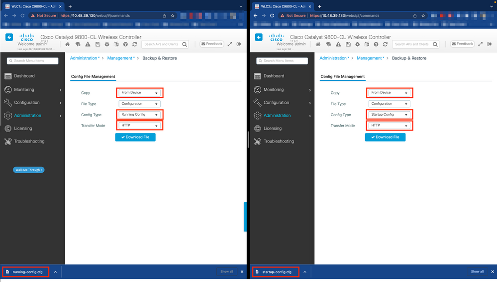
In this example, both startup (left-hand side) and configuration (right-hand side) are directly downloaded, through HTTP, on the device that hosts the browser used to access the GUI of the WLC. You can easily tweak the transfer mode and destination of the file to be backed up, with the Transfer Mode field.
From the CLI:
WLCx#copy running-config tftp://<SERVER-IP>/run-backup_x.cfg
Address or name of remote host [<SERVER-IP>]?
Destination filename [run-backup_x.cfg]?
!!
19826 bytes copied in 1.585 secs (12509 bytes/sec)
WLCx#copy startup-config tftp://<SERVER-IP>/start-backup_x.cfg
Address or name of remote host [<SERVER-IP>]?
Destination filename [start-backup_x.cfg]?
!!
20482 bytes copied in 0.084 secs (243833 bytes/sec)
Replace the <SERVER-IP> by the TFTP server IP toward which the startup/running configuration file is copied to.
Step 2. (Optional) Ensure network connectivity.
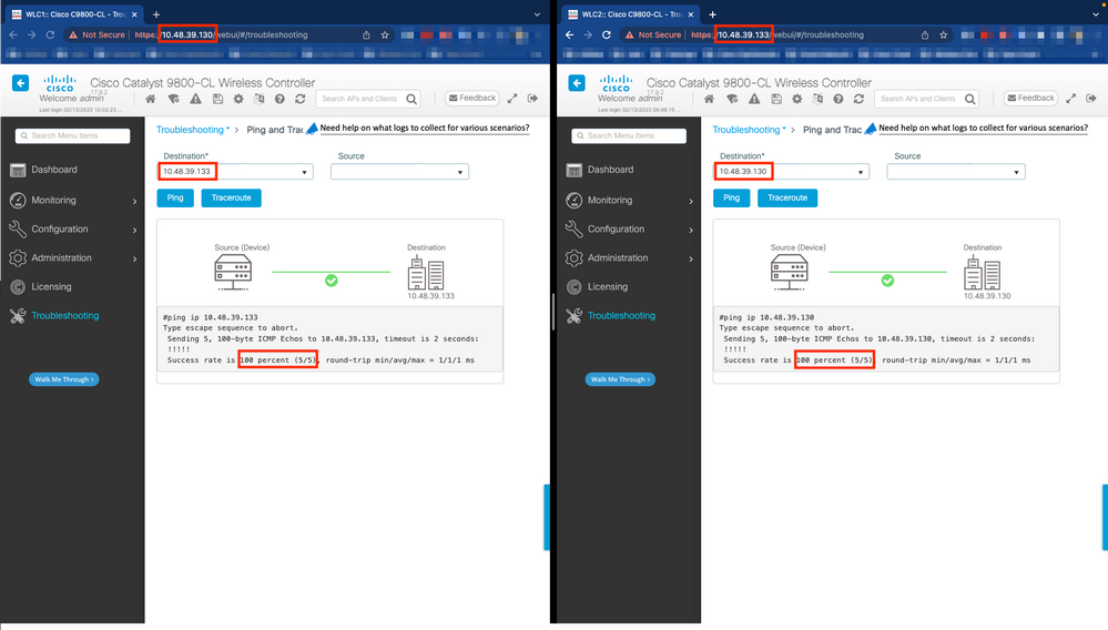
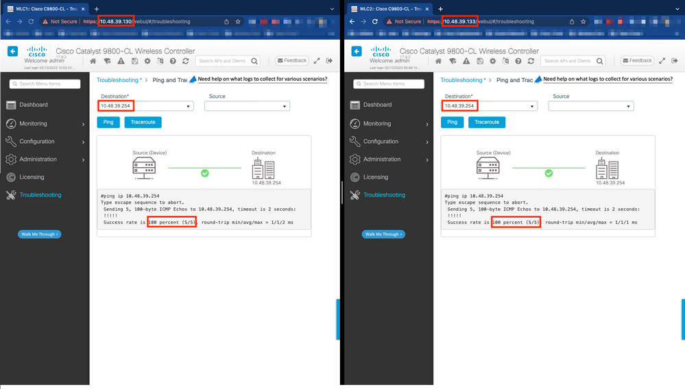
From both WLC GUIs or CLIs, you can perform simple connectivity tests, namely ping the gateway from both devices and ping the devices between themselves. This ensures that both controllers have the required connectivity in order to configure HA.
From the GUI:
The Ping and Traceroute tool from the Troubleshooting tab of the 9800 GUI can be used in order to test connectivity between the controllers themselves and between each WLC and its network gateway, as shown in these figures.
From the CLI:
WLCx#ping 10.48.39.133
Type escape sequence to abort.
Sending 5, 100-byte ICMP Echos to 10.48.39.133, timeout is 2 seconds:
!!!!!
Success rate is 100 percent (5/5), round-trip min/avg/max = 1/1/1 ms
WLCx#ping 10.48.39.254
Type escape sequence to abort.
Sending 5, 100-byte ICMP Echos to 10.48.39.254, timeout is 2 seconds:
!!!!!
Success rate is 100 percent (5/5), round-trip min/avg/max = 1/1/1 ms
Step 3. Configure redundancy with RMI + RP pairing type.
With connectivity between each device ensured, redundancy can be configured between the controllers. This screen capture shows how the configuration is made from the Redundancy tab of the Administration > Device page of the 9800 GUI.


Warning: For this example, WLC1 has been designated as primary controller, which means that this is the one whose configuration is replicated to the other controller. Make sure you apply the proper chassis priority/renumber in order to use the proper configuration with your HA pair and not lose any part of it.
Review the configured fields and their purpose.
- Redundancy Configuration: this must be enabled in order to use redundancy between WLCs.
- Redundancy Pairing Type: since this guide covers HA SSO using RMI configuration, the pairing type configured must be RMI + RP, using both redundancy management interface and redundancy port. One can also choose to configure redundancy using only the redundancy port. However, when RP only is chosen, the reachability of the gateway is not checked, only the redundant WLC state is checked.
- RMI IP for Chassis 1/2: these fields assign the provided IP addresses to the designated redundancy interface for both instances. In this example, both RMI IPs for chassis 1 and 2 have been configured as being respectively 10.48.39.131 and 10.48.39.132, as described before and shown in the network diagram.
- HA Interface: when using virtual appliances, the mapping between the virtual network interfaces cards (vNIC) of the hypervisor and the network interfaces of the virtual machine can be configured in different ways. Therefore, the interface used for redundancy is configurable for Cisco Catalyst 9800-CLs. Here, the GigabitEthernet 3 has been used, as recommended by the 9800-CL deployment guide.

Note: When using physical C9800 appliances, the interface used in HA and RP are the default one and are not configurable. Indeed, hardware 9800 WLCs have a dedicated redundancy interface which is separated from their network ones.
-
Management Gateway Failover: as detailed in the HA SSO configuration guide, this redundancy method implements default gateway check, done by periodically sending Internet Control Message Protocol (ICMP) ping to the gateway. Both the active and the standby controllers use the RMI IP as the source IP for these checks. These messages are sent at 1 second interval.
-
Gateway Failure Interval: this represents the amount of time for which a gateway check must consecutively fail before the gateway is declared as non-reachable. By default, this is configured as 8 seconds. Since gateway checks are sent every second, this represents 8 consecutive failures to reach the gateway.
-
Local/Remote IP: these are the RP IP configured for chassis 1 and 2. These IP addresses are auto-generated as 169.254.x.x, where x.x is derived from the last two octets of the management interface.
-
Keep Alive Timer: as detailed in the HA SSO configuration guide, the Active and standby chassis send keep-alive messages to each other to ensure that both are still available. The keep alive timer is the amount of time separating the sending of 2 keepalive messages between each chassis. By default, keep-alive messages are sent each 100 ms. It is often recommended to increase this value with 9800-CL to avoid abusive switchovers anytime the VM infrastructure introduces small delays (snapshots, and so on ...)
-
Keep Alive Retries: this field configures the peer keepalive retry value before it claims that the peer is down. If both keep-alive timer and retried default value are used, a peer is claimed down if the 5 keep alive messages sent at 100 ms time interval are left unanswered (that is if the redundancy link is down for 500 ms).
-
Chassis Renumber: the chassis number that the appliance must use (1 or 2).
-
On WLC2 (10.48.39.133), the chassis is renumbered to 2. By default, chassis number is 1. IP addresses of RP ports are derived from RMI. If the chassis number is the same on both controllers, local RP port IP derivation is the same and discovery fails. Renumber the chassis to avoid this so-called Active-Active scenario.
-
-
Active Chassis Priority: the priority used to define which configuration must be used by the HA pair. The appliance with the highest priority is the one which is replicated to the other. The configuration of the chassis with the lowest priority is therefore lost.
-
On WLC1 (10.48.39.130), the active chassis priority has been set to 2. This is to make sure that this chassis is chosen as the active one (and therefore, that its configuration is used) in the created HA pair.
-
Once these configuration are made, use the Apply button to apply the configuration to the controllers.
From the CLI
First, configure a secondary IP address in the virtual interface used to configure the RMI on both devices.
WLC1#configure terminal
WLC1(config)#interface vlan 39
WLC1(config-if)# ip address 10.48.39.131 255.255.255.0 secondary
WLC1(config-if)# end
WLC2#configure terminal
WLC2(config)#interface vlan 39
WLC2(config-if)# ip address 10.48.39.132 255.255.255.0 secondary
WLC2(config-if)# endThen, enable redundancy on both devices.
WLC1#configure terminal
WLC1(config)#redundancy
WLC1(config-red)#mode sso
WLC1(config-red)#end
WLC2#configure terminal
WLC2(config)#redundancy
WLC2(config-red)#mode sso
WLC2(config-red)#end
Configuring chassis priority, such as WLC1, becomes the primary controller.
WLC1#show chassis
Chassis/Stack Mac Address : 0001.0202.aabb - Local Mac Address
Mac persistency wait time: Indefinite
                                             H/W   Current
Chassis#   Role    Mac Address     Priority Version  State                 IP
-------------------------------------------------------------------------------------
*1       Active   0001.0202.aabb     1      V02     Ready                169.254.39.131
WLC1#chassis 1 priority 2
WLC1#show chassis
Chassis/Stack Mac Address : 0001.0202.aabb - Local Mac Address
Mac persistency wait time: Indefinite
                                             H/W   Current
Chassis#   Role    Mac Address     Priority Version  State                 IP
-------------------------------------------------------------------------------------
*1       Active   0001.0202.aabb     2      V02     Ready                169.254.39.131
Renumber chassis for WLC2, which becomes the secondary controller.
WLC2#show chassis
Chassis/Stack Mac Address : 0001.0202.aabb - Local Mac Address
Mac persistency wait time: Indefinite
                                             H/W   Current
Chassis#   Role    Mac Address     Priority Version  State                 IP
-------------------------------------------------------------------------------------
*1       Active   0001.0202.aabb     1      V02     Ready                169.254.39.132
WLC2#chassis 1 renumber 2
WLC2#show chassis
Chassis/Stack Mac Address : 0001.0202.aabb - Local Mac Address
Mac persistency wait time: Indefinite
                                             H/W   Current
Chassis#   Role    Mac Address     Priority Version  State                 IP
-------------------------------------------------------------------------------------
*2       Active   0001.0202.aabb     1      V02     Ready                169.254.39.132
Finally, configure RMI on both devices.
WLC1#chassis redundancy ha-interface GigabitEthernet 3
WLC1#configure terminal
WLC1(config)#redun-management interface Vlan39 chassis 1 address 10.48.39.131 chassis 2 address 10.48.39.132
WLC1(config)#end
WLC2#chassis redundancy ha-interface GigabitEthernet 3
WLC2#configure terminal
WLC2(config)#redun-management interface Vlan39 chassis 1 address 10.48.39.131 chassis 2 address 10.48.39.132
WLC2(config)#end
Note: As for the GUI configuration, on virtual Catalyst 9800, the interface used by the controller must be selected between the ones available. As recommended, GigabitEthernet 3 is used here and configured thanks to the chassis redundancy ha-interface GigabitEthernet 3 command. This command is not part of the running configuration, however the interface used by HA can be seen in the instance ROMMON environment variables. These can be seen using the show romvarcommand.
Step 4. Reload controllers.
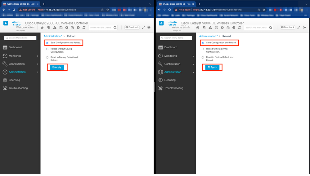
For the HA pair to form and the configuration to be effective, both controllers must be reloaded at the same time once the configuration made at step 3 has been saved.
From GUI:
One can use the Administration Reload page of both GUI to restart the controllers, such as depicted in this screen capture.
From CLI:
WLCx#reload
Reload command is being issued on Active unit, this will reload the whole stack
Proceed with reload? [confirm]
Note: If you are using a AAA server, you need to add both the WMI IP address as well as the RMI IP address as AAA clients on your AAA server. The standby WLC always uses its RMI IP to authenticate SSH sessions. The active WLC uses both RMI and WMI to reach out to the AAA server.
Verify
Once both controllers of the HA pair discover each other and create the desired HA pair, one controller (the primary) is able to monitor the two chassis from the GUI or CLI.
From GUI:
To monitor the redundancy configuration from the 9800 GUI, navigate to the Redundancy tab from the Monitoring > General > System page, as depicted in this screen capture.

From CLI:
WLC#show chassis rmi
Chassis/Stack Mac Address : 0050.568d.cdf4 - Local Mac Address
Mac persistency wait time: Indefinite
                                             H/W   Current
Chassis#   Role    Mac Address     Priority Version  State                 IP                RMI-IP
--------------------------------------------------------------------------------------------------------
*1       Active   0050.568d.cdf4     2      V02     Ready                169.254.39.131     10.48.39.131
 2       Standby  0050.568d.2a93     1      V02     Ready                169.254.39.132     10.48.39.132
WLC#show redundancy
Redundant System Information :
------------------------------
Available system uptime = 22 minutes
Switchovers system experienced = 0
Standby failures = 0
Last switchover reason = none
Hardware Mode = Duplex
Configured Redundancy Mode = sso
Operating Redundancy Mode = sso
Maintenance Mode = Disabled
Communications = Up
Current Processor Information :
-------------------------------
Active Location = slot 1
Current Software state = ACTIVE
Uptime in current state = 22 minutes
Image Version = Cisco IOS Software [Cupertino], C9800-CL Software (C9800-CL-K9_IOSXE), Version 17.9.2, RELEASE SOFTWARE (fc2)
Technical Support: http://www.cisco.com/techsupport
Copyright (c) 1986-2022 by Cisco Systems, Inc.
Compiled Wed 02-Nov-22 15:12 by mcpre
BOOT = bootflash:packages.conf,12;
CONFIG_FILE =
Configuration register = 0x102
Recovery mode = Not Applicable
Fast Switchover = Enabled
Initial Garp = Enabled
Peer Processor Information :
----------------------------
Standby Location = slot 2
Current Software state = STANDBY HOT
Uptime in current state = 20 minutes
Image Version = Cisco IOS Software [Cupertino], C9800-CL Software (C9800-CL-K9_IOSXE), Version 17.9.2, RELEASE SOFTWARE (fc2)
Technical Support: http://www.cisco.com/techsupport
Copyright (c) 1986-2022 by Cisco Systems, Inc.
Compiled Wed 02-Nov-22 15:12 by mcpre
BOOT = bootflash:packages.conf,12;
CONFIG_FILE =
Configuration register = 0x102Troubleshoot
One Stop-Shop Reflex
The usual show tech wireless does not include commands that allow to understand the HA failovers of an HA pair nor its current status properly. Collect this command in order to have most HA-related commands in a single operation :
WLC#show tech wireless redundancyShow Commands
For the status of the redundancy ports, these commands can be used.
WLC#show chassis detail
Chassis/Stack Mac Address : 0050.568d.2a93 - Local Mac Address
Mac persistency wait time: Indefinite
                                             H/W   Current
Chassis#   Role    Mac Address     Priority Version  State                 IP
-------------------------------------------------------------------------------------
 1       Standby  aaaa.aaaa.aaaa     2      V02     Ready                169.254.39.131
*2       Active   bbbb.bbbb.bbbb     1      V02     Ready                169.254.39.132


         Stack Port Status             Neighbors
Chassis#  Port 1     Port 2           Port 1   Port 2
--------------------------------------------------------
  1         OK         OK               2        2
  2         OK         OK               1        1
WLC#show chassis rmi
Chassis/Stack Mac Address : 0050.568d.2a93 - Local Mac Address
Mac persistency wait time: Indefinite
                                             H/W   Current
Chassis#   Role    Mac Address     Priority Version  State                 IP                RMI-IP
--------------------------------------------------------------------------------------------------------
 1       Standby  aaaa.aaaa.aaaa     2      V02     Ready                169.254.39.131     10.48.39.131
*2       Active   bbbb.bbbb.bbbb     1      V02     Ready                169.254.39.132     10.48.39.132
This command shows the chassis number and the Redundancy Port Status, helpful as a first step troubleshoot.
In order to verify the keepalive counters on the keepalive port, you can use these commands.
WLC#show platform software stack-mgr chassis active R0 sdp-counters
Stack Discovery Protocol (SDP) Counters

---------------------------------------

Message                 Tx Success    Tx Fail       Rx Success    Rx Fail
------------------------------------------------------------------------------
Discovery               162054        2             28            0
Neighbor                23            3             12            0
Keepalive               189856        1665          187970        0
SEPPUKU                 0             0             0             0
Standby Elect Req       2             0             0             0
Standby Elect Ack       0             0             2             0
Standby IOS State       0             0             4             0
Reload Req              0             0             0             0
Reload Ack              0             0             0             0
SESA Mesg               0             0             0             0
RTU Msg                 0             0             0             0
Disc Timer Stop         1             0             2             0

---------------------------------------

WLC#show platform software stack-mgr chassis standby R0 sdp-counters
Stack Discovery Protocol (SDP) Counters

---------------------------------------

Message                 Tx Success    Tx Fail       Rx Success    Rx Fail
------------------------------------------------------------------------------
Discovery               14            2             19            0
Neighbor                6             2             5             0
Keepalive               175905        0             176196        0
SEPPUKU                 0             0             0             0
Standby Elect Req       0             0             1             0
Standby Elect Ack       1             0             0             0
Standby IOS State       2             0             0             0
Reload Req              0             0             0             0
Reload Ack              0             0             0             0
SESA Mesg               0             0             0             0
RTU Msg                 0             0             0             0
Disc Timer Stop         1             0             0             0

---------------------------------------

WLC#show platform software stack-mgr chassis standby R0 peer-timeout
Peer Chassis    Peer-timeout (ms)   50% Mark            75% Mark
--------------------------------------------------------------------------
2               500                 0                   0
Other Commands
It is possible to take a packet capture on the Redundancy Port of the controller with these commands:
WLC#test wireless redundancy packetdump start
Redundancy Port PacketDump Start

Packet capture started on RP port.

WLC#test wireless redundancy packetdump stop
Redundancy Port PacketDump Stop

Packet capture stopped on RP port.
Captures made using these commands are saved in the bootflash: of the controller, under the name haIntCaptureLo.pcap.
You can also run a keepalive test on the Redundancy Port with this command.
WLC#test wireless redundancy rping
Redundancy Port ping

PING 169.254.39.131 (169.254.39.131) 56(84) bytes of data.
64 bytes from 169.254.39.131: icmp_seq=1 ttl=64 time=0.316 ms
64 bytes from 169.254.39.131: icmp_seq=2 ttl=64 time=0.324 ms
64 bytes from 169.254.39.131: icmp_seq=3 ttl=64 time=0.407 ms

--- 169.254.39.131 ping statistics ---
3 packets transmitted, 3 received, 0% packet loss, time 2025ms
rtt min/avg/max/mdev = 0.316/0.349/0.407/0.041 ms
Get into More Details
To view the ROMMON Variables configuration which shows us how the actual configuration is being reflected on the variables, you can use this command.
WLC#show romvar
ROMMON variables:
 MCP_STARTUP_TRACEFLAGS = 00000000:00000000
 SWITCH_NUMBER = 2
 CONFIG_FILE =
 BOOTLDR =
 STACK_1_1 = 0_0
 BOOT = bootflash:packages.conf,12;
 LICENSE_SUITE =
 CHASSIS_HA_IFNAME = GigabitEthernet3
 CHASSIS_HA_IFMAC = 00:50:56:8D:2A:93
 SWITCH_PRIORITY = 1
 RMI_INTERFACE_NAME = Vlan39
 RMI_CHASSIS_LOCAL_IP = 10.48.39.132
 RMI_CHASSIS_REMOTE_IP = 10.48.39.131
 CHASSIS_HA_LOCAL_IP = 169.254.39.132
 CHASSIS_HA_REMOTE_IP = 169.254.39.131
 CHASSIS_HA_LOCAL_MASK = 255.255.255.0
 RET_2_RTS =
 LICENSE_BOOT_LEVEL = ,csr1000v:csr1000v;
 BSI = 0
 RET_2_RCALTS =
 RANDOM_NUM = 193112462
This command shows the priority for the chassis, both RMI and RP details, peer timeout along with more helpful details.
You can also monitor the processes that run HA SSO on the WLC which are two processes, namely stack_mgr and rif_mgr.
To do this, collect the always on traces to a text file using the command, the time parameter here can be adjusted to cover the time frame you want to troubleshoot.
show logging process stack_mgr start last 30 minutes to-file bootflash:stack_mgr_logs.txt
show logging process rif_mgr start last 30 minutes to-file bootflash:rif_mgr_logs.txt 
Note: It is important to note that the Service Port of the standby WLC is deactivated and unreachable while the controller is acting as standby.
Typical Scenarios
User Forced
If you look at the switchover history, you can see user forced, appearing when a user initiated a switchover between the controllers, using the redundancy force-switchovercommand.
WLC#show redundancy switchover history
Index  Previous  Current  Switchover             Switchover
       active    active   reason                 time
-----  --------  -------  ----------             ----------
   1       1        2     user forced            11:38:23 Central Fri Mar 10 2023
Active Unit Removed
If you look at the switchover history, you can see active unit removed, which points to a loss of communication on the Redundancy Port between the two controllers.
WLC#show redundancy switchover history
Index  Previous  Current  Switchover             Switchover
       active    active   reason                 time
-----  --------  -------  ----------             ----------
   2       2        1     active unit removed    11:55:36 Central Fri Mar 10 2023
This can happen if the link between the two controllers goes down, but it can also happen if one WLC unit suddenly goes down (power failure) or crashes. It is interesting to monitor both WLCs to see if they have system reports which indicate unexpected crashes/reboots.
Active Lost GW
If you look at the switchover history, you can see Active lost GW which points to a loss of communication with the gateway on RMI port.
WLC#show redundancy switchover history
Index  Previous  Current  Switchover             Switchover
       active    active   reason                 time
-----  --------  -------  ----------             ----------
   3       1        2     Active lost GW         12:00:26 Central Fri Mar 10 2023
This happens if the link between the active controller and its gateway goes down.
Further Considerations
Enabling Console access for the standby 9800
Login to the CLI of the active WLC and run this command to enable to console access to the standby 9800. Otherwise console access is locked to the standby WLC :
WLC#conf t
Enter configuration commands, one per line.  End with CNTL/Z.
WLC(config)#redundancy

WLC(config-red)#main-cpu

WLC(config-r-mc)#standby console enable
HA SSO for Catalyst 9800-CL
When in virtual environments, you need to accept that latency is introduced, and latency is not something that HA tolerates properly. This is legitimate, since HA SSO tends to detect quickly and efficiently any chassis fault. To achieve this, each chassis checks the status of the other by using keepalives on both RP and RMI links as well as pings toward the gateway of their RMIs (and this, the one of their WMI which must be the same). If any of these are missed, the stack reacts depending on the symptoms as detailed in the System and Network Fault Handling from the HA SSO guide.
When working with virtual HA SSO stacks of Catalyst 9800, it is common to observe switchovers due to keepalive missed over the RP link. This can be due to latency introduced by the virtualized environment.
To determine if the HA SSO stack suffers from RP keepalive drops,you can use the stack/rif manager logs.
! Keepalives are missed
004457: Feb  4 02:15:50.959 Paris: %STACKMGR-6-KA_MISSED: Chassis 1 R0/0: stack_mgr: Keepalive missed for 2 times for Chassis 2
! Chassis is removed
%STACKMGR-6-CHASSIS_REMOVED_KA: Chassis 1 R0/0: stack_mgr: Chassis 2 has been removed from the stack due to keepalive failure.
! RP link is down
004469: Feb  4 02:17:28.707 Paris: %RIF_MGR_FSM-6-RP_LINK_DOWN: Chassis 1 R0/0: rif_mgr: Setting RP link status to DOWN
! Dual active detection
004470: Feb  4 02:17:28.707 Paris: %STACKMGR-1-DUAL_ACTIVE_CFG_MSG: Chassis 1 R0/0: stack_mgr: Dual Active Detection links are not available anymore
If both chassis are operating, then the switchover creates a Dual active detection which is a consequence of the drops on RP.
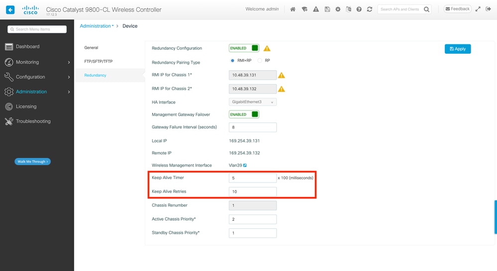
In such situation, tweaking HA keepalive parameters to avoid these unnecessary switchovers, can help. Two parameters can be configured,
- Keep Alive Timer: the amount of time separating the sending of 2 keepalive messages between each chassis.
- Keep Alive Retries: the number of keepalive that needs to be missed to declare a peer down.
By default, the keep alive timer is set to 1ms and the retries to 5. This means that after 5ms of keepalive being missed on the RP link, a switchover occurs. These values can be too low for virtual deployments. If you are experiencing recurring switchover due to RP keepalives being missed, try increasing these parameters to stabilize the stack.
From GUI:
To monitor or modify the HA SSO keepalive parameters from the 9800 GUI, navigate to the Redundancy tab from the Administration > Device page, as depicted in this screenshot.
From CLI:
WLC#chassis redundancy keep-alive retries <5-10>
WLC#chassis redundancy keep-alive timer <1-10>
Along with the configuration of these parameters, another optimization can help with such a behavior in the HA SSO stack. For physical appliance, hardware allows to connect a chassis to another usually using a single wire. In a virtual environment, the interconnection of the RP port for each chassis must be made by a virtual switch (vSwitch), which can once again introduce latency compared to physical connections. Using a dedicated vSwitch to create the RP link is another optimization that can prevent HA keepalives lost due to latency. This is also documented in the Cisco Catalyst 9800-CL Wireless Controller for Cloud Deployment Guide. Therefore, the best is to use a dedicated vSwitch for RP link between the 9800-CL VMs and make sure no other traffic interferes with it.
Catalyst 9800 HA SSO Inside ACI Deployments
When a switchover occurs in a HA SSO stack, the newly active chassis uses the gratuitous ARP (GARP) mechanism to update the MAC to IP mapping in the network and make sure it receives traffic dedicated to the controller. In particular, the chassis send GARP to become the new owner of the WMI and make sure CAPWAP traffic reach the proper chassis.
The chassis becoming active is actually not sending one single GARP, but a burst of them in order to make sure any device in the network updates its IP to MAC mapping. This burst can overwhelm the ARP learning feature of ACI and thus, when ACI is used, it is recommended to reduce this burst as much as possible from the Catalyst 9800 configuration.
From CLI:
WLC# configure terminal
WLC(config)# redun-management garp-retransmit burst 0 interval 0
Along with limiting the GARP burst initiated by the 9800 during a switchover, it is also recommended to disable the fast switchover feature on this platform. When fast switchover is configured, the active controller sends an explicit notification to the standby controller, stating that it is going down. While using this, interleaving traffic can exist (APs and clients being dropped) between both WLCs forming the HA stack until one of them goes down. Thus, disabling this feature helps stabilize your wireless infrastructure while working with ACI deployments.
From CLI:
WLC#configure terminal
WLC(config)#no redun-management fast-switchover
Caution: Keep in mind that when fast switchover is disabled, the standby controller relies solely on the keepalive timeout failures to detect when the active controller went down. These must therefore be configured with the utmost care.
Details about considerations for HA SSO deployments for Catalyst 9800 inside ACI network can be seen in the Information About Deploying ACI Network in Controller section of the Cisco Catalyst 9800 Series Wireless Controller Software Configuration Guide.
References
Revision History
| Revision | Publish Date | Comments |
|---|---|---|
8.0 |
27-Dec-2024 |
Added a note about standby WLC console access |
7.0 |
13-Dec-2024 |
Updated Alt Text, Link Targets, and Formatting. |
6.0 |
16-Jul-2024 |
updated versions and added a note about RMI interface for AAA |
5.0 |
06-Jun-2024 |
Added a section "further considerations" |
4.0 |
25-Feb-2024 |
Added a note about Service Port |
3.0 |
19-Feb-2024 |
small modification about 9800-CL interface configuration |
2.0 |
26-Jun-2023 |
Fixed Gig3 IP addressing |
1.0 |
10-Mar-2023 |
Initial Release |
Contributed by Cisco Engineers
- Guilian DeflandreTechnical Consulting Engineer
- Rasheed HamdanTechnical Consulting Engineer
Contact Cisco
- Open a Support Case

- (Requires a Cisco Service Contract)
 Feedback