Implement Software-Defined Access for Wireless with DNAC
Available Languages
Download Options
Bias-Free Language
The documentation set for this product strives to use bias-free language. For the purposes of this documentation set, bias-free is defined as language that does not imply discrimination based on age, disability, gender, racial identity, ethnic identity, sexual orientation, socioeconomic status, and intersectionality. Exceptions may be present in the documentation due to language that is hardcoded in the user interfaces of the product software, language used based on RFP documentation, or language that is used by a referenced third-party product. Learn more about how Cisco is using Inclusive Language.
Contents
Introduction
This document describes how to implement SDA for wireless technology related to fabric enabled WLC and access LAP on DNAC.
Prerequisites
Requirements
Cisco recommends that you have knowledge of these topics:
- 9800 Wireless LAN Controllers (WLC) configuration
-
Lightweight Access Points (LAPs)
- DNA Center (DNAC)
Components Used
The information in this document is based on these software and hardware versions:
- 9800-CL WLC Cisco IOS® XE, Version 17.9.3
- Cisco Access Points: 9130AXE, 3802E, 1832I
- DNA Center (DNAC) version 2.3.3.7
The information in this document was created from the devices in a specific lab environment. All of the devices used in this document started with a cleared (default) configuration. If your network is live, ensure that you understand the potential impact of any command.
SD-Access
Software-Defined Access establishes and automatically enforces security policies across the network, with dynamic rules and automated segmentation, and allows the end user to control and configure how the users connect to their network. SD-Access establishes an initial level of trust with each endpoint that is connected, and continuously monitors it to re-verify its level of trust. If an endpoint behaves not normaly or a treat is detected, the end user can immediately contain it an take action, before breach takes place, reduces business risk, and protects its resources. Fully integrated solution and easy to deploy and configure on both new and deployed networks.
SD-Access is a Cisco technology that is an evolution of the traditional campus network that delivers intent-based networking (IBN) and central policy control with the use of Software-Defined Networking (SDN) components.
Three network-centric pillars of SD-Access:
- A network fabric: It is an abstraction of the network itself that supports programmable overlays and virtualization. The network fabric supports both wired and wireless access, allows it to host multiple logical networks that are segmented from one other and are defined by business intent.
- Orchestration: DNA Center is the orchestrator engine of SDA. DNA Center functions like an SDN controller. It implements policies and configuration changes in the fabric. Also incorporates a tool that supports network design and supports real-time network telemetry operations and performance analytics through DNA Assurance. The role of DNA Center is to orchestrate the network fabric to deliver policy changes and network intent for security, quality of service (QoS), and microsegmentation.
- Policy: Identity Services Engine (ISE) is the tool that defines network policy. ISE organizes how the devices and nodes are segmented into virtual networks. ISE also defines scalable group tags (SGTs) that are used by access devices to segment user traffic as it enters the fabric. SGRs are responsible to enforce the microsegmentation policy defined by ISE.
SDA is built on centralized orchestration. The combinations of DNA Center as the programmable orchestration engine, ISE as the policy engine, and a new generation of programmable switches makes it a much more flexible and manageable fabric system than anything that has come before.

Note: This document deals specifically with SD-Access Wireless.
The network fabric is composed of these elements:
 Elements of Network Fabric
The wireless integration to fabric leads to several advantages for the wireless network for example: addressing simplification, mobility with stretched subnets across physical locations; and microsegmentation with centralized policy that is consistent across both of the wired and wireless domains. It also enables the controller to shed data plane to forward duties while it continues to function as the centralized services and control plane for the wireless network. Thus wireless controller scalability is actually increased because it no longer needs to process data plane traffic, similar to the FlexConnect model.
SD-Access Wireless Architecture
Overview
 SDA Overview
There are two primary SDA supported wireless deployment models:
One is an over-the-top (OTT) method, a traditional CAPWAP deployment connected on top of a fabric wired network. The SDA fabric transports the CAPWAP control and data plane traffic to the wireless controller:
 Over-The-Top Method
In this deployment model, the SDA fabric is a transport network for wireless traffic (a model often deployed in migrations). The AP works very similarly to classic Local mode: both CAPWAP control and data planes terminate on the controller, that means the controller does not directly participate in the fabric. This model is often used when wired switches are first migrated to the SDA fabric but the wireless network is not yet ready for full fabric overlay integration.
The other deployment models the fully integrated SDA model. The wireless network is fully integrated to the fabric and participates in overlays, it allows different WLANs to be part of different virtual networks (VNs). The wireless controller only manages the CAPWAP control plane (to manage APs), and the CAPWAP data plane does not come to the controller:
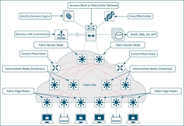 Fully Integrated SDA Model
The wireless data plane is handled similarly to wired switches - each AP encapsulates data in VXLAN and sends it to a fabric edge node where it is then sent across the fabric to another edge node. The wireless controllers must be configured as fabric controllers, which is a modification from their normal operation.
Fabric enabled controllers communicate with the fabric control plane, it registers Layer 2 client MAC addresses, and Layer 2 Virtual Network Identifier (VNI) information. The APs are responsible for communication with wireless endpoints, and assist the VXLAN data plane by encapsulation and de-encapsulation traffic.
SDA Roles & Terminology
The network fabric is composed of these elements:
- Control-Plane Node: This is the location mapping system (host database) that is part of the Location Separator Protocol (LISP) control plane, that manages endpoint identity (EID) to location relationships (or device relationships). Either the control plane can be a dedicated router that provided control plane functions or it can coexist with other fabric network elements.
- Fabric Border Nodes: Typically a router that functions at the border between external networks and the SDA fabric, that provides routing services to the virtual networks in the fabric. It connects external Layer 3 network(s) to the SDA fabric.
- Fabric Edge Nodes: Device within the fabric that connects non-fabric devices, such as switches, APs, and routers to the SDA fabric. These are the nodes that create the virtual overlays tunnels and VNs with Virtual eXtensible LAN (VXLAN) and impose the SGTs on fabric-bound traffic. The networks on both sides of the fabric edge are inside the SDA network. They connect wired endpoints to the SD-Access fabric.
- Intermediate Nodes: These nodes are inside the core of the SDA fabric and connect to either edge or border nodes. The intermediate nodes simply forward SDA traffic as IP packets, unaware that there are multiple virtual networks involved.
- Fabric WLC: Wireless controller that is fabric enabled and participates in the SDA control plane but does not proccess the CAPWAP data plane.
- Fabric mode APs: Access points that are fabric enabled. Wireless traffic is VXLAN-encapsulated at the AP, which allows it to be sent into the fabric through an edge node.
-
DNA Center (DNAC): The Enterprise SDN controller for the Software Defined Access (SDA) fabric overlay network, and is responsible for both automation and assurance tasks. It can also be utilized for some automation and related tasks for the network devices that form the underlay (that is non-SDA related) as well.
-
ISE: The Identity Services Engine (ISE) is an enhanced policy platform that can serve a variety of roles and functions, not the least of which is that of the Authentication, Authorization and Accounting (AAA) server. ISE typically interacts with Active Directory (AD), but users can be configured locally as well on ISE itself for smaller deployments.

Note: The control plane is a critical infrastructure piece of the SDA architecture, so it is recommended to be deployed in a resilient way.
Underlay and Overlay Networks
The SDA architecture utilizes fabric technology that supports programmable virtual networks (overlay networks) that run on a physical network (an underlay network).
A fabric is an Overlay.
An Overlay network is a logical topology used to virtually connect devices, built over an arbitrary physical Underlay topology. It uses alternate forward attributes to provide additional services that are not provided by the Underlay. It is created on top of the underlay to create one or more virtualized and segmented networks. Due to the software-defined nature of overlays, it is possible to connect them in very flexible ways without the constraints of physical connectivity. It is an easy way to enforce security policies, since the overlay can be programmable to have a single physical exit point (the fabric border node), and one firewall can be used to protect the networks behind it (whether they can be located). Overlay encapsulates traffic with the use of VXLAN. VXLAN encapsulates complete Layer 2 frames for transport across the underlay with each overlay network identified by a VXLAN network identifier (VNI). Overlay fabrics tend to be complex and require a significant amount of administrator overhead on new virtual networks deployed, or to implement security policies.
Examples of network overlays:
- GRE, mGRE
- MPLS, VPLS
- IPSec, DMVPN
- CAPWAP
- LISP
- OTV
- DFA
- ACI
An Underlay network is defined by the physical nodes such as switches, routers, and wireless APs that are used to deploy the SDA network. All network elements of the underlay must establish IP connectivity via the use of a routing protocol. While the underlay network is not likely to use the traditional access, distribution, core model, it must use a well-designed Layer 3 foundation that delivers robust performance, scalability, and high availability.

Note: SDA supports IPv4 in the underlay network and IPv4 and/or IPv6 in overlay networks.
 Underlay and Overlay Networks
Basic Workflows
AP join
 AP Join Workflow
AP Join Workflow:
1. Admin configures AP pool in DNAC in INFRA_VN. Cisco DNA Center pre-provision a configuration on all the Fabric Edge Node to automatically onboard APs.
2. AP is plugged in and powers up. Fabric Edge discovers it’s an AP via CDP and applies the macro to assign (or the interface template) the switch port the the right VLAN.
3. AP gets an IP address via DHCP in the overlay.
4. Fabric Edge registers APs IP address and MAC (EID) and updates the Control Plane (CP).
5. AP learns WLCs IP with traditional methods. Fabric AP joins as a Local mode AP.
6. WLC checks if it is fabric-capable (Wave 2 or Wave 1 APs).
7. If AP is supported for Fabric, WLC queries the CP to know if AP is connected to Fabric.
8. Control Plane (CP) replies to WLC with RLOC. This means AP is attached to Fabric and is shown as “Fabric enabled”.
9. WLC does a L2 LISP registration for AP in CP (that is AP “special” secure client registration). This is used to pass important metadata information from WLC to the Fabric Edge.
10. In response to this proxy registration, Control Plane (CP) notifies Fabric Edge and pass the metadata received from WLC (flag that says it isan AP and the AP IP address).
11. Fabric Edge processes the information, it learns it is an AP and creates a VXLAN tunnel interface to the specified IP (optimization: switch side is ready for clients to join).
The debug/show commands can be used to verify and validate the AP join workflow.
Control Plane
debug lisp control-plane all
show lisp instance-id <L3 instance id> ipv4 server (must show the AP IP address registered by edge switch where the AP is connected)
show lisp instance-id <L2 instance id> ethernet server (must show the AP radio as well as ethernet mac-address, AP radio registered by the WLC and ethernet mac by the edge switch where the AP is connected)
Edge switch
debug access-tunnel all
debug lisp control-plane all
show access-tunnel summary
show lisp instance < L2 instance id> ethernet database wlc access-points (must show the AP radio mac here)
WLC
show fabric ap summary
WLC LISP debugs
set platform software trace wncd chassis active r0 lisp-agent-api debug
set platform software trace wncd chassis active r0 lisp-agent-db debug
set platform software trace wncd chassis active r0 lisp-agent-fsm debug
set platform software trace wncd chassis active r0 lisp-agent-internal debug
set platform software trace wncd chassis active r0 lisp-agent-lib debug
set platform software trace wncd chassis active r0 lisp-agent-lispmsg debug
set platform software trace wncd chassis active r0 lisp-agent-shim debug
set platform software trace wncd chassis active r0 lisp-agent-transport debug
set platform software trace wncd chassis active r0 lisp-agent-ha debug
set platform software trace wncd chassis active r0 ewlc-infra-evq debug
Access Point
show ip tunnel fabric
Client Onboard
 Client Onboard Workflow
Client Onboard Workflow:
1. Client authenticates to a Fabric enabled WLAN. WLC gets SGT from ISE, updates AP with client L2VNID and SGT along with RLOC IP. WLC knows RLOC of AP from internal Database.
2. WLC proxy registers Client L2 info in CP; this is LISP modified message to pass additional info, like the client SGT.
3. Fabric edge gets notified by CP and adds client MAC in L2 to the forward table and go and fetch the policy from ISE based on the client SGT.
4. Client initiates DHCP Request.
5. AP encapsulates it in VXLAN with L2 VNI information.
6. Fabric Edge maps L2 VNID to VLAN interface and forwards DHCP in the overlay (same as for a wired Fabric client).
7. Client receives an IP address from DHCP.
8. DHCP snooping (and/or ARP for static) triggers the client EID registration by the Fabric Edge to the CP.
The debug/show commands can be used to verify and validate the client onboard workflow.
Control Plane
debug lisp control-plane all
Edge switch
debug lisp control-plane all
debug ip dhcp snooping packet/event
WLC
For LISP communication same debugs as AP join
Client Roams
 Client Roams Workflow
Client Roams Workflow:
1. Client roams to AP2 on FE2 (inter-switch roaming). WLC gets notified by AP.
2. WLC updates forward table on AP with client info (SGT, RLOC).
3. WLC updates the L2 MAC entry in CP with new RLOC Fabric Edge 2.
4. CP then notifies:
- Fabric Edge FE2 (”roam-to” switch) to add the client MAC to the forward table that points to VXLAN tunnel.
- Fabric Edge FE1 (”roam-from” switch) to do clean up for the wireless client.
5. Fabric Edge update the L3 entry (IP) in CP data base upon it receives traffic.
6. Roam is Layer 2 as Fabric Edge 2 has the same VLAN interface (Anycast GW).
Configure
Network Diagram
 Network Diagram
WLC Discovery & Provision in DNA Center
Add WLC
Step 1. Navigate to the location where you want to add the WLC. You can add a new building/floor.
Navigate to Design > Network Hierarchy and enter the building/floor, or you can create a new floor, as shown in the image:
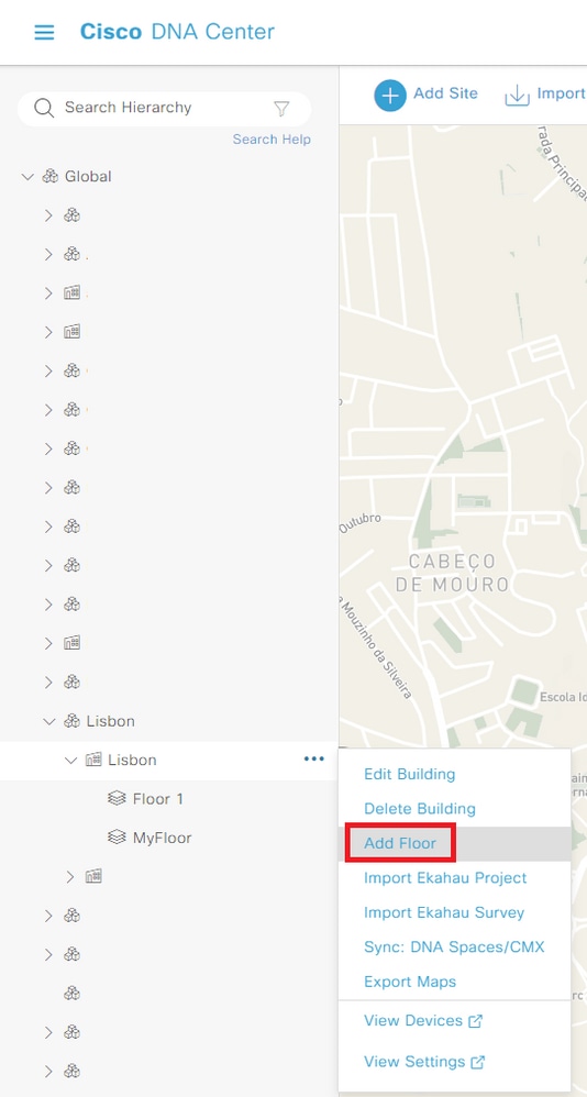 Create New Floor
Step 2. Add floor. You can also upload an image of the plant of the floor.
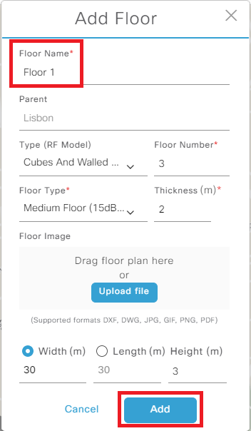 Add New Floor
Step 3. Navigate to Provision > Inventory and add the WLC on Add Device. Add a username/password to the WLC which is used by DNAC to access the WLC.
:
 Add Device
Step 4. On the WLC GUI, navigate to Administration > Management > SNMP > Community Strings and verify the string configured. You need to add the correct SNMP community string when you add the WLC on DNAC, and ensure that netconf-yang is enabled on the 9800 WLC with 'show netconf-yang status' commands. At the end click Add:
 SNMP Configuration
Step 5. Add the WLC IP address, CLI credentials (the credentials DNAC uses to log in to the WLC and these must be configured on the WLC before add it to DNAC), the SNMP string and verify if the NETCONF port is configured on port 830:
 Add WLC
The WLC shows up as NA because DNAC is still in sync process:
 WLC in Sync Process
When it finishes the sync process, you can see the WLC name, IP address, if it is reachable, managed and software version:
 WLC Synced
Step 6. Assign the WLC to a site. On the device list click on Assign and choose a site:
 Assign Device to Site
You can decide to assign the site now or later:
 Assign Device to Site Now or Later
Add Access Points
Step 1.Once the WLC is added and reachable, navigate to Provision > Inventory > Global > Unassigned Devices and search for the APs that you have joined to your WLC:
 Add Access Points
Step 2. Select the option Assign. Assign the APs to a site. Tick the box Apply to All to make the configuration for more than one device at the same time.
 Assign APs to Site
Navigate to your floor and you can see all devices assigned to it - WLC and APs:
 Devices Assigned to the Site
Create SSID
Step 1. Navigate to Design > Network Settings > Wireless > Global and add an SSID:
 Create SSID
You can create an Enterprise SSID or a Guest SSID. In this demo a Guest SSID is created:
 Enterprise or Guest SSID
Step 2. Choose the setting you want for the SSID. In this case, an open SSID is created. Admin status and Broadcast SSID must be enabled:
 SSID Basic Settings
 SSID Security Settings

Caution: Do not forget to configure and associate AAA server for the SSID. The default method list is mapped if no AAA server are configured.
When you click next you can see advanced settings for your SSID:
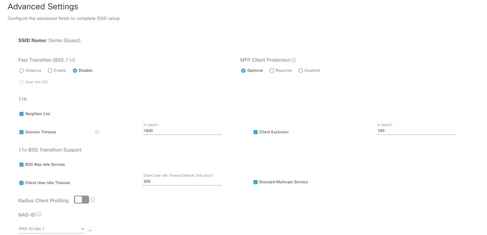 SSID Advanced Settings
Step 3. After the creation of the SSID, you need to associate it to a profile. Click Add Profile:
 Add Profile
Step 4. Give a name to the profile, select Fabric and at the end click on Associate Profile:
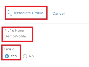 Associate Profile
You are presented with a summary of the SSID and profile you created:
 SSID Summary
Step 5. Configure a new network profile:
 Configure Network Profile
To create a new network profile without a new SSID creation, navigate to Design > Network Profiles, select Add Profile > Wireless:
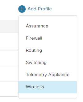 Add Network Profile Wireless
Step 6. Create the network profile. Give it a name and associate the SSID:
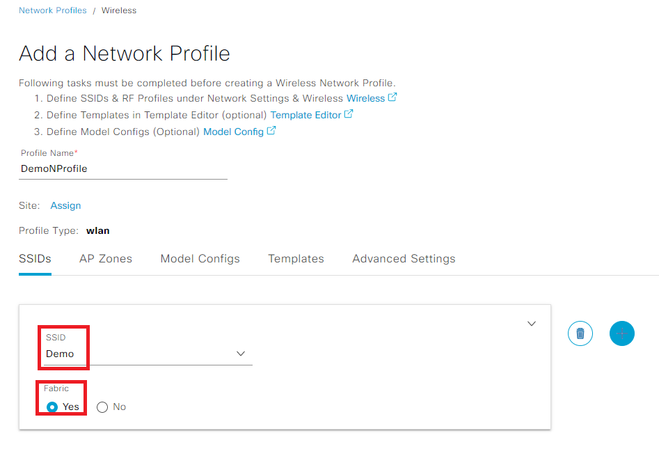 Create Network Profile
Provision WLC
Step 1. Navigate to your building/floor. Select the WLC and Actions > Provision > Provision Device:
 Provision WLC
Step 2. Verify the WLC configurations before provision it. Make sure that you add an AP location:

Step 3. Verify the device details, network settings, and SSIDs before provision it. If all is well, select Deploy:
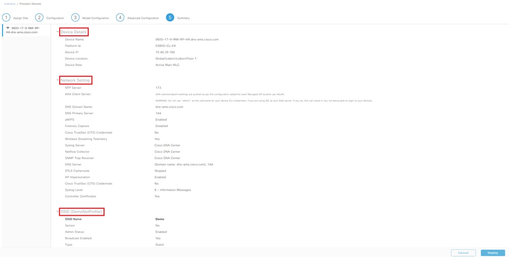 Deploy WLC Provision
Step 4. The device provision can be deployed at the moment or later. At the end select Apply:
 Provision WLC Now or Later
The WLC is now provisioned.
Step 5. On the WLC side, navigate to Configuration > Wireless > Fabric and enable fabric status:
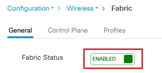 Enable Fabric Status
Step 6. Navigate to Configuration > Wireless > Fabric > Control Plane and edit a control plane. Add the IP address and PSK. Click Update & Apply to Device:
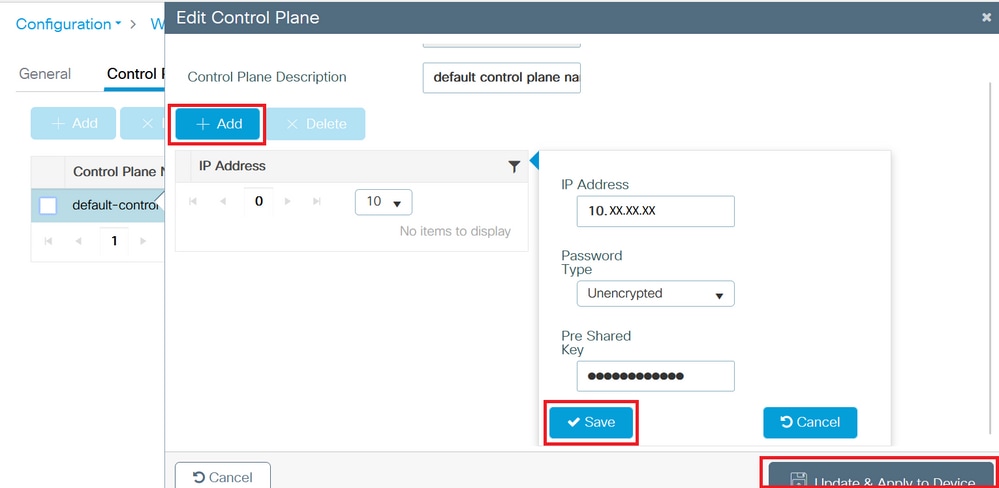 Add Control Plane
Step 7. (Optional) Create a new RF profile. Navigate to Design > Network Settings > Wireless > Global and add the new RF profile:
 Add RF Profile
Step 8. (Optional) Give a name to the RF profile and select the settings you want to configure. In this demo, the default settings were configured. Click Save:
 Add Basic RF Profile
Provision Access Points
Step 1. Navigate to your building/floor. Select the APs and Actions > Provision > Provision Device:
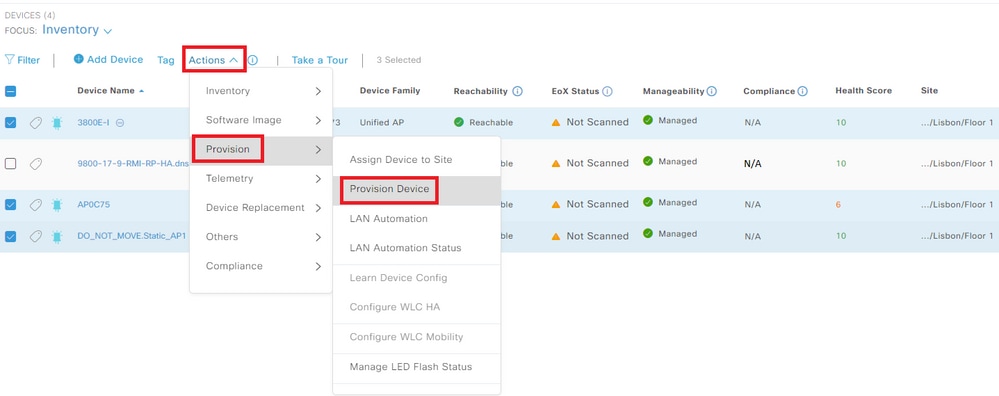 Provision APs
Step 2. Verify if the assigned site is correct and select Apply to All:
 Assign Site to APs
Step 3. Select a RF Profile from the drop down list and verify is the SSID is the correct one:
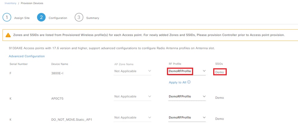 Select RF Profile
Step 4. Verify the settings on the APs, if all is well select Deploy:
 Deploy APs Provision
Step 5. The device provision can be deployed at the moment or later. At the end select Apply:
 Provision APs Now or Later

Caution: When provision the APs, which are already part of the configured floor for the selected RF profile is be processed and rebooted.
The APs are now provisioned.
Step 6. On the WLC side, navigate to Configuration > Wireless > Access Points. Verify that the AP tags were pushed from the DNAC:
 Tags on APs
Step 7. Navigate to Configuration > Tags & Profiles > WLANs and verify that the SSID was pushed from DNAC:
 WLAN
WLAN
Create Fabric Site
Step 1. Navigate to Provision > Fabric Sites. Create a fabric site:
 Create Fabric Sites
Step 2. Select the building/floor for your fabric site:
 Select Fabric Site
Step 3. Select an authentication template. In this demo None was applied:
 Authentication Template
Step 3. You can choose if you want to set up the fabric zone now or later:
 Setup Fabric Zones
Step 4. Verify the settings of your fabric zone. If all is well, select Deploy:
 Deploy Fabric Site
You have created a Fabric Site:
 Fabric Site Create
Add WLC to Fabric
Navigate to Provision > Fabric Sites and select your fabric site. Click on top of your WLC and navigate to the tab Fabric. Enable fabric to the WLC, and select Add:
 Add WLC to Fabric
AP Join
Step 1. Navigate to Design > Network Settings > IP Address Pools. Create an IP Address Pool.
 IP Address Pool
Step 2. Navigate to Provision > Fabric Sites and select your fabric site. Navigate to Host Onboarding > Virtual Networks.
INFRA_VN is introduced to easily onboard APs. APs are in the Fabric overlay but INFRA_VN is mapped to the global routing table. Only APs and Extended nodes can belong to INFRA_VN. “Layer 2 Extension” is automatically enabled and turn on L2 LISP service.
Select INFRA_VN > Add:
 Edit Virtual Network
Step 3. Add an IP Address Pool with Pool Type as AP:
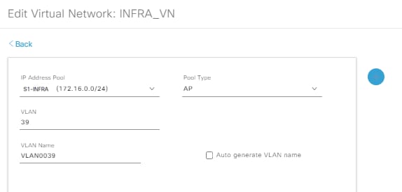 Edit Virtual Network S1-INFRA
Step 4. Verify if the Layer-2 Extension is enabled.
 Edit Virtual Network
With Pool Type = AP and Layer-2 extension to ON, DNA Center connects to the WLC and sets the Fabric interface to VN_ID mapping for the AP subnet for both L2 & L3 VN_IDs.
Step 5. On WLC GUI side, navigate to Configuration > Wireless > Fabric > General. Add a new client and AP VN_ID:
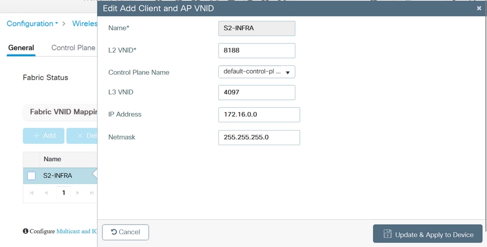 Add new Client and AP VN_ID
Step 6. Navigate to Configuration > Wireless > Access Points. Select one AP from the list. Verify that the Fabric Status is Enabled, the IP address of the control plane and the control plane name:
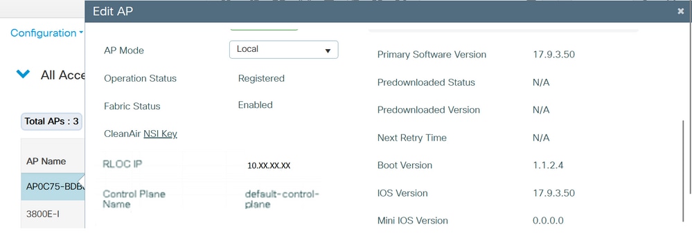 Verify AP Fabric Status
Client Onboard
Step 1. Add the pool to Virtual Network and verify that Layer-2 Extension toggle is ON to enable L2 LISP and Layer 2 subnet extension on the client Pool/subnet. In DNA Center 1.3.x you cannot disable it.
 Add IP Address Pool
Step 2. Verify if the Layer-2 Extension and Wireless Pool are enabled.
 Edit Virtual Network
Step 3 . On WLC GUI side, navigate to Configuration > Wireless > Fabric > General. Add a new client and AP VN_ID.
When the pool is assigned to the Virtual Network, the correspondent Fabric interface to VNID mapping is pushed to the controller. Note: these are all L2 VNID.
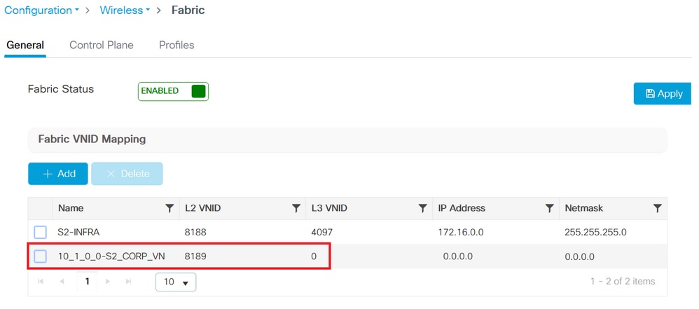 Add new Client and AP VN_ID
Step 4. SSIDs are mapped to the pool in the respective Virtual Networks:
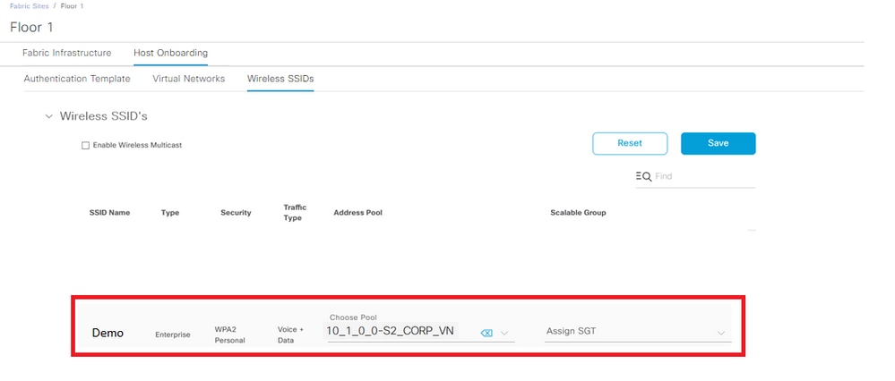 Mapped SSIDs
Step 5. A Fabric Profile with the L2 VNID is added to the pool chosen and the Policy Profile is mapped to the Fabric profile, it isenabled for Fabric.
On the WLC GUI side, navigate to Configuration > Wireless > Fabric > Profiles.
 Fabric Profile
Step 6. Navigate to Configuration > Tags & Profiles > Policy. Verify the fabric profile mapped to the policy profile:
 Fabric Profile configured on the Policy
Verify
Verify fabric configuration on WLC and DNAC
On the WLC CLI:
WLC1# show tech
WLC1# show tech wireless
Control plane configuration:
router lisp
locator-table default
locator-set WLC
172.16.201.202
exit-locator-set
!
map-server session passive-open WLC
site site_uci
description map-server configured from Cisco DNA-Center
authentication-key 7 <Key>
CB1-S1#sh lisp session
Sessions for VRF default, total: 9, established: 5
Peer State Up/Down In/Out
172.16.201.202:4342 Up 3d07h 14/14
WLC configuration:
wireless fabric
wireless fabric control-plane default-control-plane
ip address 172.16.2.2 key 0 47aa5a
WLC1# show fabric map-server summary
MS-IP Connection status
--------------------------------
172.16.1.2 UP
WLC1# show wireless fabric summary
Fabric Status : Enabled
Control-plane:
Name IP-address Key Status
--------------------------------------------------------------------------------------------
default-control-plane 172.16.2.2 47aa5a Up
On the WLC GUI navigate to Configuration > Wireless > Fabric and verify if the Fabric Status is Enabled.
Navigate to Configuration > Wireless > Access Points. Select one AP from the list. Verify that the Fabric Status is Enabled.
On DNAC navigate to Provision > Fabric Sites and verify if you have a fabric site. On that fabric site navigate to Fabric Infrastructure > Fabric and verify if the WLC is enabled as fabric.
Troubleshoot
Client does not get IP address
Step 1. Verify if the SSID is fabric. On WLC GUI, navigate to Configuration > Tags & Profiles > Policy. Select the policy and navigate to Advanced. Verify if the Fabric Profile is enabled.
Step 2. Check if the client is stuck in IP learn state. On WLC GUI, navigate to Monitoring > Wireless > Clients. Verify the client state.
Step 3. Verify if the policy is DHCP required.
Step 4. If the traffic is locally switched between AP - edge node, collect AP logs (client-trace) for client connection. Verify if the DHCP discovery is forwarded. If no DHCP offer arrives, something is wrong on the edge node. If the DHCP is not forwarded, then something is wrong on the AP.
Step 5. You can collect an EPC on the edge node port to see the DHCP discover packets. If you do not see the DHCP discover packets, the problem is on the AP.
SSID is not broadcasted
Step 1. Verify if the AP radios are down.
Step 2. Check if the WLAN is on status and broadcast SSID enabled.
Step 3. Verify AP configuration if AP is fabric enabled. Navigate to Configuration > Wireless > Access Points, select one AP and on General tab you can see Fabric Status Enabled and the RLOC information.
Step 4. Navigate to Configuration > Wireless > Fabric > Control Plane. Verify if the control plane is configured (with the IP address).
Step 5. Navigate to Configuration > Tags & Profiles > Policy. Select the policy and navigate to Advanced. Verify if the Fabric Profile is enabled.
Step 6. Navigate to DNAC and re-do the steps on Create SSID and Provision WLC. The DNAC must push the SSID to the WLC again.
Related Information
Revision History
| Revision | Publish Date | Comments |
|---|---|---|
1.0 |
27-Apr-2023 |
Initial Release |
Contributed by Cisco Engineers
- Marta CoelhoCisco Technical Consulting Engineer
Contact Cisco
- Open a Support Case

- (Requires a Cisco Service Contract)
 Feedback