Configure Validate and Troubleshoot Wireless QoS on 9800 WLC
Available Languages
Download Options
Bias-Free Language
The documentation set for this product strives to use bias-free language. For the purposes of this documentation set, bias-free is defined as language that does not imply discrimination based on age, disability, gender, racial identity, ethnic identity, sexual orientation, socioeconomic status, and intersectionality. Exceptions may be present in the documentation due to language that is hardcoded in the user interfaces of the product software, language used based on RFP documentation, or language that is used by a referenced third-party product. Learn more about how Cisco is using Inclusive Language.
Contents
Introduction
This document describes ways to configure, validate and troubleshoot wireless Quality of Service (QoS) on 9800 Wireless LAN Controller (WLC).
Components Used
The information in this document is based on these software and hardware versions:
- WLC: C9800-40-K9 running 17.12.03
- Access Point (AP): C9120-AXE-D
- Switch: C9300-48P running 17.03.05
- Wired and Wireless Client: Windows 10
The information in this document was created from the devices in a specific lab environment. All of the devices used in this document started with a cleared (default) configuration. If your network is live, ensure that you understand the potential impact of any command.
Background Information
Wireless QoS is essential for ensuring that critical applications receive the necessary bandwidth and low latency required for optimal performance. This document provides a comprehensive guide to configuring, validating, and troubleshooting QoS on Cisco wireless networks.
This article assumes that readers have a foundational understanding of both wireless and wired QoS principles. It is also expected that readers are proficient in configuring and managing Cisco WLCs and APs.
Configuration
This section delves into the configuration of QoS on 9800 wireless controllers. By leveraging these configurations, you can ensure that critical applications receive the necessary bandwidth and low latency, thereby optimizing overall network performance.
You can divide the 9800 WLC QoS configuration into mainly three different broad categories.
 9800 WLC QOS Configuration Summary
This document goes through each section one by one in the subsequent sections.

Note: This article focuses on AP in local mode. AP in Flexconnect mode is not discussed.
QoS Policy Targets
A policy target is the configuration construct where a QoS policy can be applied. The QoS implementation on the Catalyst 9800 is modular and flexible. The user can decide to configure policies at three different targets: the SSID, client, and port levels.
 QoS Policy Targets
The SSID policy is applicable per AP per SSID. You can configure policing and marking policies on SSID.
Client policies are applicable in the ingress and egress direction. You can configure policing and marking policies on clients. AAA override is also supported.
The port-based QoS policies can be applied at a physical or at a logical port.
Auto QoS
Wireless Auto QoS automates the deployment of wireless QoS features. It has a set of predefined profiles that can be further modified by the admin to prioritize different traffic flows. Auto-QoS matches traffic and assigns each matched packet to QoS groups. This allows the output policy map to put specific QoS groups into specific queues, including the priority queue.
|
Mode |
Client Ingress |
Client Egress |
BSSID Ingress |
BSSID Egress |
Port Ingress |
Port Egress |
Radio |
|
Voice |
N/A |
N/A |
platinum-up |
platinum |
N/A |
AutoQos-4.0-wlan-Port-Output-Policy |
ACM on |
|
Guest |
N/A |
N/A |
AutoQos-4.0-wlan-GT-SSID-Input-Policy |
AutoQos-4.0-wlan-GT-SSID-Output-Policy |
N/A |
AutoQos-4.0-wlan-Port-Output-Policy |
|
|
Fastlane |
N/A |
N/A |
N/A |
N/A |
N/A |
AutoQos-4.0-wlan-Port-Output-Policy |
edca-parameters fastlane |
|
Enterprise-avc |
N/A |
N/A |
AutoQos-4.0-wlan-ET-SSID-Input-AVC-Policy |
AutoQos-4.0-wlan-ET-SSID-Output-Policy |
N/A |
AutoQos-4.0-wlan-Port-Output-Policy |
This table depicts the configuration changes that happen when an auto QoS profile is applied.
To configure Auto QoS navigate to Configuration > QoS
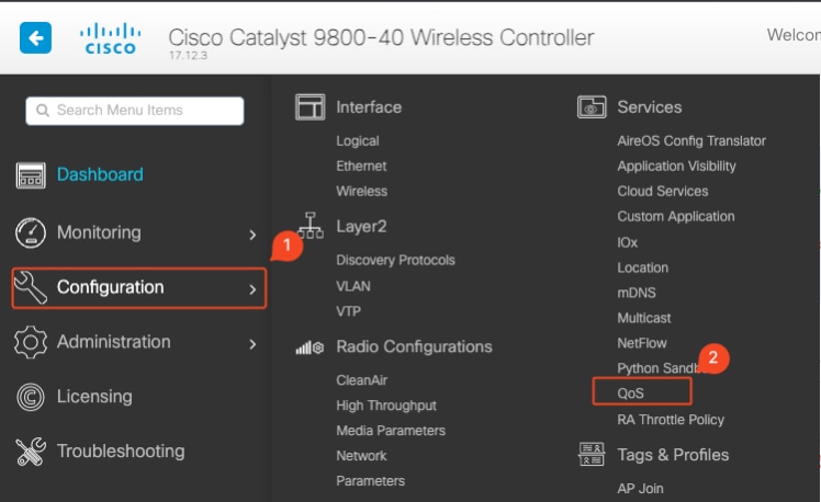 QoS Workflow
Click on Add and set Auto QoS to enabled. Choose the appropriate Auto QoS macro from the list. For this example, Voice macro to prioritize voice traffic is used.
 AutoQoS Voice Mapping
Once the macro is enabled, select the policy that needs to be attached to the policy.
Auto QoS CLI configuration
# enable
# wireless autoqos policy-profile default-policy-profile mode voice
Now that Auto QoS is enabled you can see the changes that happened. This section lists the configuration changes for voice.
class-map match-any AutoQos-4.0-Output-CAPWAP-C-Class
 match access-group name AutoQos-4.0-Output-Acl-CAPWAP-C
class-map match-any AutoQos-4.0-Output-Voice-Class
 match dscp ef
policy-map AutoQos-4.0-wlan-Port-Output-Policy
 class AutoQos-4.0-Output-CAPWAP-C-Class
  priority level 1
 class AutoQos-4.0-Output-Voice-Class
  priority level 2
 class class-default
interface TenGigabitEthernet0/0/0
 service-policy output AutoQos-4.0-wlan-Port-Output-Policy
interface TenGigabitEthernet0/0/1
 service-policy output AutoQos-4.0-wlan-Port-Output-Policy
interface TenGigabitEthernet0/0/2
 service-policy output AutoQos-4.0-wlan-Port-Output-Policy
interface TenGigabitEthernet0/0/3
 service-policy output AutoQos-4.0-wlan-Port-Output-Policy
ip access-list extended AutoQos-4.0-Output-Acl-CAPWAP-C
 10 permit udp any eq 5246 16666 any
wireless profile policy qos-policy
 autoqos mode voice
 service-policy input platinum-up
 service-policy output platinum
ap dot11 24ghz cac voice acm
ap dot11 5ghz cac voice acm
ap dot11 6ghz cac voice acm
Modular QoS CLI
The MQC allows you to define a traffic class, create a traffic policy (policy map), and attach the traffic policy to an interface. The traffic policy contains the QoS feature that applies to the traffic class.
 MQS CLI Workflow
This example demonstrates how to use Access Control Lists (ACLs) to classify traffic and apply bandwidth restrictions.
Create an ACL to identify and classify the specific traffic you want to manage. This can be done by defining rules that match traffic based on criteria such as IP addresses, protocols, or ports.
Navigate to Configuration > Security > ACL and add the ACL.
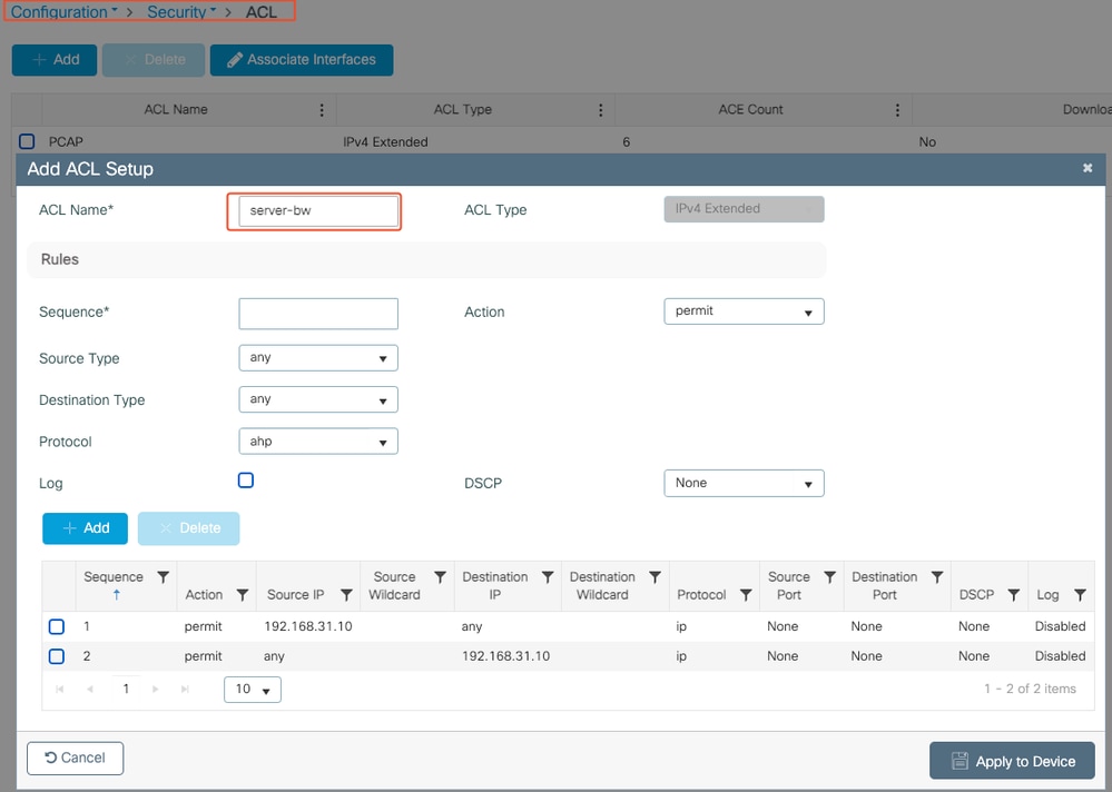 ACL Configuration
Once the traffic is classified using the ACL, configure bandwidth restrictions to control the amount of bandwidth allocated to this traffic.
Navigate to Configuration > Services > QoS and the QoS policy. Attach the ACL inside the policy and apply the police in kbps.
Scroll down and select the policy profile where the QoS is to be applied. You can select the policy in ingress/ egress direction for both SSID or Client.
 MQS Policy
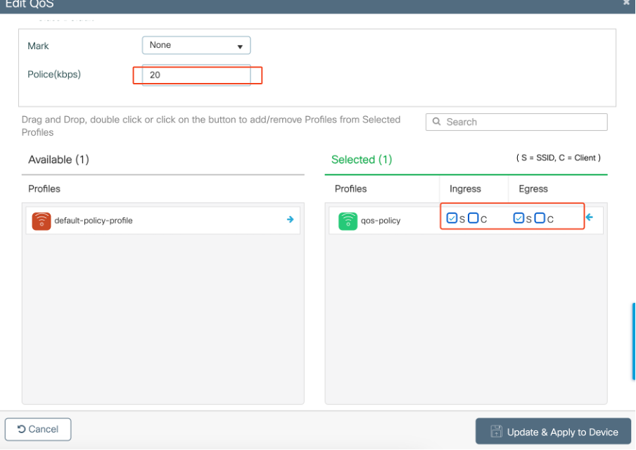 MQS Profile
MQS CLI configuration
ip access-list extended server-bw
1 permit ip host 192.168.31.10  any
!
class-map match-any server-bw
match access-group name server-bw
!
policy-map server-bw
class server-bw
  police cir 100000
   conform-action transmit
   exceed-action drop
exit
class class-default
police cir 20000
conform-action transmit
exceed-action drop
exit
wireless profile policy default-policy-profile
service-policy input server-bw
service-policy output server-bw
exit
Metal QoS
The primary purpose of these QoS profiles is to limit the maximum Differentiated Services Code Point (DSCP) values allowed on a wireless network, thereby controlling the 802.11 User Priority (UP) values.
In the Cisco 9800 Wireless LAN Controller (WLC), the Metal QoS profiles are predefined and not configurable. However, you can apply these profiles to specific SSIDs or clients to enforce QoS policies.
There are four Metal QoS profiles available:
|
Qos Profile |
Max DSCP |
|
Bronze |
8 |
|
Silver |
0 |
|
Gold |
34 |
|
Platinum |
46 |
To configure Metal QoS on a Cisco 9800 WLC:
Navigate to Configuration > Policy > QoS & AVC.
- Select the desired Metal QoS profile (Platinum, Gold, Silver, or Bronze).
- Apply the chosen profile to the target SSID or client.
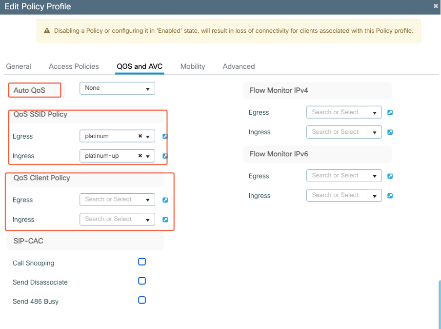 Metal QoS Profile
Metal QoS CLI Configuration
#configure terminal
#wireless profile policy qos-policy
 service-policy input platinum-up
 service-policy output platinum

Note: Per-user and SSID bandwidth contract are configurable via QoS policies and not directly on the Metal QoS. In 9800 the non-matching traffic goes in the default class.

Note: On the GUI, you can only set the Metal QoS per SSID. On CLI you can also configure it on the client target.
Validate End-to-End QoS with Packet Capture
Now that the QoS configuration is completed, it is essential to examine QoS packets and validate that the QoS policies are functioning correctly from end to end. This can be achieved through packet capture and analysis.
To replicate and validate the QoS configuration, a small-scale lab environment is used. The lab includes these components:
- WLC
- AP
- Sniffer AP to take OTA
- Wired PC
- Switch
All these components are connected to the same switch within the lab environment. The highlighted numbers in this diagram indicate the points where packet captures are enabled to monitor and analyze the traffic flow.
Network Diagram
 LAB Topology
Lab Components and Packet Capture Points
WLC:
- Manages the QoS policies and configurations for the wireless network.
- Packet capture point: Capture traffic between the WLC, AP and switch.
AP:
- Provides wireless connectivity to clients and enforces QoS policies.
- Packet capture point: Capture traffic between the AP and the switch.
Sniffer AP:
- Acts as a dedicated device for capturing wireless traffic.
- Packet capture point: Capture wireless traffic between the AP and wireless clients.
Wired PC:
- Connected to the switch to simulate wired traffic and validate end-to-end QoS.
- Packet capture point: Capture transmitted and received QoS packets over wired link.
Wireless PC:
- Connected to the WLAN to simulate wireless traffic and validate end-to-end QoS.
- Packet capture point: Capture transmitted and received QoS packets over wireless link.
Switch:
- The central device that interconnects all lab components and facilitates traffic flow.
- Packet capture points: Capture traffic at various switch ports to validate proper QoS enforcement.
Logically the LAB topology can be drawn like this.
 Logical LAB Topology
To test and validate the QoS configuration, iPerf is used to generate traffic between the client and the server. These commands are used to facilitate iPerf communication, with the roles of the server and client interchanged based on the direction of the QoS testing.
Test Scenario 1: Downstream QoS validation
The aim to validate the downstream QoS configuration. The setup involves a wired PC sending packets with DSCP 46 to a wireless PC.
The Wireless LAN Controller (WLC) is configured with the Metal "Platinum QoS" policy for both downstream and upstream directions.
Test Setup:
- Traffic Flow:
Source: Wired PC
Destination: Wireless PC
Traffic Type: UDP Packets with DSCP 46
- QoS Policy Configuration on WLC:
QoS Profile: Metal QoS - Platinum QoS
Direction: Both downstream and upstream
- Metal QoS Configuration Commands:
wireless profile policy qos-policy
service-policy input platinum-up
service-policy output platinum
Logical topology and the DSCP conversation at downstream direction.
 DSCP Conversation Point
Packet Capture taken on the wired PC. This confirms that the wired PC is sending UDP packets to the specified destination IP 192.168.10.13 with the correct DSCP marking of 46.
 Wired PC Capture - Downstream Direction
Next, let us examine a packet captured on the uplink switch connected to the wired PC. The switch trusts the DSCP tag and the DSCP value remains unchanged at 46.

Note: Switch ports on the Catalyst 9000 series default to a trusted state.
 Wired PC Uplink Interface Capture
Upon examining the packet capture on the WLC taken using EPC, The packet arrives with the same DSCP tag of 46 from the uplink switch. This confirms that the DSCP marking is preserved as the packet reaches the WLC.
 WLC EPC Downstream Direction
When the WLC sends the packet to the AP inside a CAPWAP tunnel, it is a critical intersection where the WLC can modify the DSCP based on its configuration. Let us break down the packet capture, which is highlighted with numbered points for clarity:
- CAPWAP Outer Layer: The outer layer of the CAPWAP tunnel shows the DSCP tag as 46, which is the value received from the switch end.
- 802.11 UP Value Inside CAPWAP: Inside the CAPWAP tunnel WLC maps the DSCP 46 to 802.11 User Priority (UP) 6, which corresponds to Voice traffic.
- DSCP Value Inside CAPWAP: The Cisco 9800 WLC operates with a trust DSCP model, so the DSCP value inside the CAPWAP tunnel is kept at 46 same as the outer DSCP layer.
 CAPWAP DSCP Markings
Next, check the same packet on the AP uplink switch port.
The DSCP value on the outer CAPWAP layer remains at 46. For illustrative purposes, the inner CAPWAP traffic is highlighted to show the tagging.
 AP Uplink Switch Interface Capture
Once the AP receives the packet, it transmits the packet over the air. To verify the User Priority (UP) tagging, an Over-the-Air (OTA) capture taken with a sniffer AP is used.
The AP has forwarded the frame with a UP value of 6. This confirms that the AP correctly maps the DSCP value to the appropriate 802.11 UP value (6), which corresponds to Voice traffic.
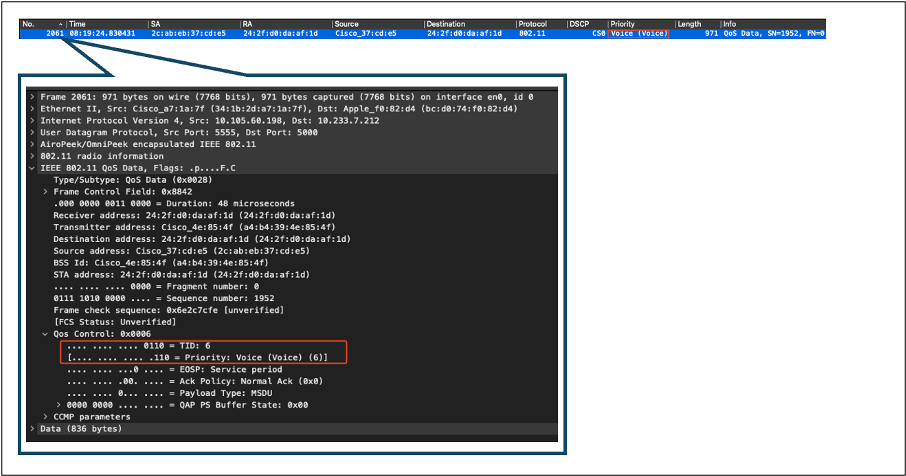 OTA Capture From AP to Client
At the final stage, the packet received by the wireless PC. The wireless PC receives the frame with a DSCP value of 46.
This indicates that the DSCP marking is preserved throughout the entire transmission path, from the wired PC to the wireless PC. The consistent DSCP value of 46 confirms that the QoS policies are correctly applied and maintained in the downstream direction.
 Wireless PC Capture
Test Scenario 2: Upstream QoS Validation
In this test scenario, the aim is to validate the upstream QoS configuration. The setup involves a wireless PC sending UDP packets with DSCP 46 to a wired PC. The WLC is configured with the Metal "Platinum QoS" policy for both upstream and downstream directions.
- Traffic Flow:
Source: Wireless PC
Destination: Wired PC
Traffic Type: UDP packets with DSCP 46
- QoS Policy Configuration on WLC:
QoS Profile: Platinum QoS
Direction: Both upstream and downstream
- Metal QoS Configuration Commands:
wireless profile policy qos-policy
service-policy input platinum-up
service-policy output platinum
Logical Topology and DSCP Conversion in upstream direction:
 Logical Topology and DSCP Conversion - Upstream
Packets sent from wireless PC to wired PC. This capture is taken at the wireless PC.
The wireless PC sends UDP packets with DSCP 46.
 Wireless PC Capture in Upstream Direction
Next let us look at the OTA capture from Client to AP.

Tip: When using a Windows wireless PC to send packets with DSCP 46, Windows maps DSCP 46 to a User Priority (UP) value of 5 (Video). As a result, the OTA capture shows the packets as Video traffic (UP 5). However, if you decrypt the packet, the DSCP value remains at 46.

Note: Starting from version 17.4, the default behaviour for the Cisco 9800 WLC is to trust the DSCP value in AP join profile. This ensures that the DSCP value of 46 is preserved and trusted by the WLC, preventing any issues related to the Windows DSCP to UP mapping behaviour.
 Windows UP to DSCP Mapping
The encrypted Over-the-Air (OTA) capture taken from the lab setup is analyzed to validate the upstream QoS configuration.
The OTA capture shows the packets with a User Priority (UP) value of 5 (Video). Although the OTA capture shows UP 5, the DSCP value inside the encrypted packet remains at 46.
 LAB Setup OTA in Upstream Direction
Next, the packet capture on the AP uplink port is analyzed to ensure that the DSCP value is preserved as the packet moves from the AP to the WLC.
- The DSCP value on the outer CAPWAP layer is maintained at 46.
- Inside the CAPWAP tunnel, the DSCP value is also kept at 46.
 AP Pplink Capture in Upstream Direction
The capture is taken at the WLC as the packet arrives from the switch.
- The packet arrives at the WLC with the DSCP value of 46 on the outer CAPWAP layer.
- Inside the CAPWAP tunnel, the DSCP value is kept at 46.
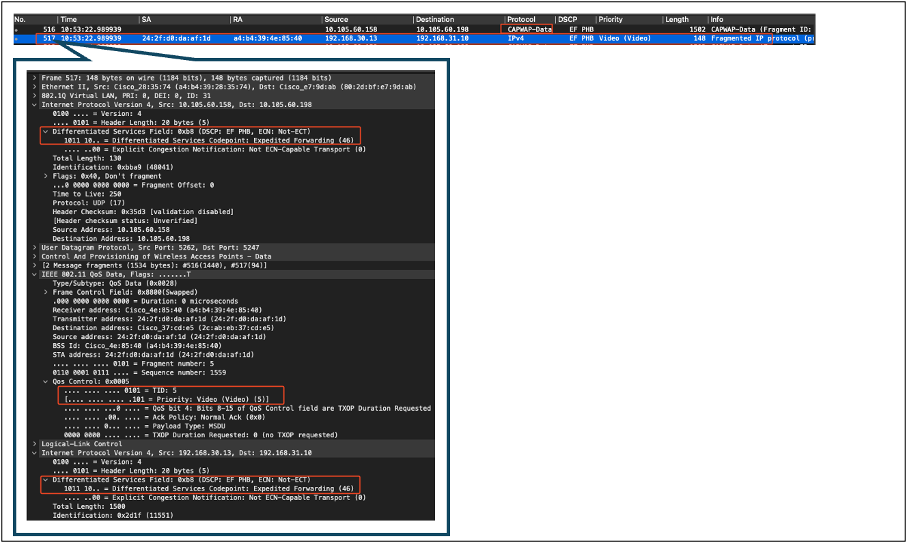 WLC EPC Showing Packets Coming From AP
After the packet takes a hairpin turn at the WLC, it is sent back to the uplink switch, destined for the wired PC. The WLC forwards the packet with the DSCP value of 46.
 WLC EPC Showing Packets Sent to Wired PC
Finally, the packet capture at the wired PC uplink is analyzed to ensure that the DSCP value is preserved as the packet arrives from the WLC.
 Wired PC Uplink Switch Capture in Upstream Direction
At the final stage, the packet received by the wired PC is analyzed to ensure that the packet arrives at the wired PC with the DSCP value of 46.
 Wired PC Capture - Upstream Direction
The upstream QoS test successfully validated the QoS configuration for traffic flowing from the wireless PC to the wired PC. The consistent preservation of the DSCP value of 46 throughout the entire transmission path confirms that the QoS policies are correctly applied and enforced.
Troubleshooting
Voice, video and other real-time applications are particularly sensitive to network performance issues, and any degradation in Quality of Service (QoS) can have noticeable and detrimental effects. When QoS packets are remarked with lower DSCP values, the impact on voice and video can be significant.
Impact on Voice:
- Increased Latency: Voice communication requires low latency to ensure that conversations are natural and fluid. Lower DSCP values can result in voice packets being delayed, causing noticeable lag in conversations.
- Jitter: Variability in packet arrival times (jitter) can disrupt the smooth delivery of voice packets. This can lead to choppy or garbled audio, making it difficult to understand the speaker.
- Packet Loss: Voice packets are highly sensitive to packet loss. Even a small amount of packet loss can result in missing words or syllables, leading to poor call quality and misunderstandings.
- Echo and Distortion: Increased latency and jitter can cause echo and audio distortion, further degrading the quality of the voice call.
Impact on Video:
- Increased Latency: Video communication requires low latency to maintain synchronization between audio and video streams. Increased latency can cause delays, making it difficult to have real-time interactions.
- Jitter: Jitter can cause video frames to arrive out of order or at irregular intervals, leading to a jerky or stuttering video experience.
- Packet Loss: Lost packets can result in missing frames, which can cause the video to freeze or display artifacts.
- Reduced Video Quality: Lower DSCP values can lead to reduced bandwidth allocation for video streams, resulting in lower resolution and poorer video quality. This can make it difficult to see important details in the video.
Scenario 1: Intermediate Switch Rewrites DSCP Marking
In this troubleshooting scenario, the impact of an intermediate switch rewriting the DSCP marking on traffic as it arrives at the WLC is investigated. To replicate this, the switch is configured to rewrite the DSCP 46 marking to CS1 on the wired PC uplink interface.
The packet is sent from the wired PC with a DSCP 46 tag.
 Wired PC Sending Packet With DSCP 46 Tag
The packet arrives at the WLC with a DSCP value of CS1 (DSCP 8). The change from DSCP 46 to DSCP 8 significantly lowers the priority of the packet.
 WLC EPC Showing CS1 Marking
In this step, the packet forwarded by the WLC to the AP is analyzed.
- The outer CAPWAP header is tagged with CS1 (DSCP 8).
- The inner CAPWAP header is also tagged with CS1 (DSCP 8).
- The User Priority (UP) value is set to BK (Background).
 WLC EPC Showing CS1 Tag in CAPWAP Traffic
The packet arrives at the wireless PC with a DSCP value of CS1 (DSCP 8).
 Wireless PC Capture Showing CS1 Marking
This scenario demonstrates how a misconfiguration on an intermediate switch can break the QoS configuration, leading to degraded performance for high-priority traffic. The voice packets, initially marked for high priority, were treated as lower-priority traffic due to the DSCP rewrite. This scenario underscores the importance of ensuring that intermediate network devices correctly preserve QoS markings to maintain the desired quality of service for high-priority traffic.
Scenario 2: AP link Switch Rewrites DSCP Marking
In this scenario, the impact of an intermediate switch connected to the AP rewriting the DSCP marking on traffic is investigated.
- The switch connected to the AP is configured to rewrite the DSCP 46 marking to a different value CS1 on the AP uplink interface.
- The packet is sent from the wired PC with a DSCP tag of 46. This confirms that the traffic is correctly marked with DSCP 46 at the source.
 Wireless PC Capture Showing DSCP 46
The capture is taken at the WLC as the packet arrives from the switch.
The packet arrives at the WLC with the outer CAPWAP header DSCP value of CS1 (DSCP
The WLC trusts the DSCP tag inside the CAPWAP tunnel and forwards the traffic to the wired PC with the inner DSCP tag of 46.
 WLC EPC Showing CAPWAP DSCP Values
The packet arrives at the wired PC with a DSCP value of 46. Confirms that the WLC correctly forwards the packet with the original DSCP value of 46, preserving the high-priority marking.
 Wired PC Received the Packet With DSCP 46
Although the WLC forwarded the traffic with a DSCP tag of 46, it is important to understand that the traffic from the AP to the WLC was treated as low priority due to the outer DSCP tag being rewritten to CS1 (DSCP 8).
There can be multiple switches between the AP and the WLC, and if the traffic is given low priority, it can arrive at the WLC late. This can lead to increased latency, jitter, and potential packet loss, which can degrade the quality of service for high-priority traffic such as voice.
Troubleshooting Tip
- Verify Initial DSCP Marking: Capture packets at the source (for example, wired PC) to ensure that the traffic is correctly marked with the intended DSCP value.
- Check Intermediate Device Configurations: Review the configuration of all intermediate switches and routers to ensure they are not inadvertently rewriting DSCP values.
- Capture Traffic at Key Points:
- Before and after the intermediate switch.
- At the WLC.
- At the destination (for example, wireless PC).
- Simulate Traffic Scenarios: Use traffic generators or network simulation tools to create different types of traffic and observe how QoS is handled by the wireless network.
- Consult 9800 best practice document: Review the 9800 best practice documentation on configuring QoS and DSCP markings.
Configuration Verification
On the WLC, these commands can be used to verify the configuration.
# show run qos
# show policy-map <policy-map name>
# show class-map <policy-map name>
# show wireless profile policy detailed <policy-profile-name>
# show policy-map interface wireless ssid/client profile-name <name> radio type 2GHz|5GHz|6GHz ap name <AP name> input|output <-- Main command.
# show policy-map interface wireless client mac <MAC> input|output
# show wireless client mac <MAC> service-policy input|output

On AP, these commands can be used to check the QoS.
# show dot11 qos
# show controllers dot11Radio 1 | begin EDCA
Conclusion
Maintaining consistent QoS configuration across the network is crucial to ensure that high-priority traffic, such as voice and video, receives the appropriate level of service and performance. It is essential to validate QoS configurations regularly to ensure that all network devices are complying with the intended QoS policies. This validation helps identify and rectify any misconfiguration or deviations that could compromise network performance.
References
- Understanding and Troubleshooting Cisco Catalyst 9800 Series Wireless Controllers
- Cisco Catalyst 9800 Series Configuration Best Practices
- Cisco Catalyst 9800 Series Wireless Controller Software Configuration Guide, Cisco IOS® XE Dublin 17.12.x
- Voice Over Wireless LAN (VoWLAN) Troubleshooting Guide
- Enable DSCP QoS Tagging on Windows Machines
Revision History
| Revision | Publish Date | Comments |
|---|---|---|
1.0 |
29-Jul-2024 |
Initial Release |
Contributed by Cisco Engineers
- Suman SinhaTechnical Consulting Engineer
Contact Cisco
- Open a Support Case

- (Requires a Cisco Service Contract)
 Feedback