Introduction
This document describes the configuration of a point-to-point link on an IW AP running in CURWB mode along with Fluidity layer 2 configuration.
Components Used
There are four different hardware:
- Cisco Catalyst IW9167
- Cisco Catalyst IW9165D
- Cisco Catalyst IW9165E
The information in this document was created from the devices in a specific lab environment. All of the devices used in this document started with a cleared (default) configuration. If your network is live, ensure that you understand the potential impact of any command.
Background Information
CURWB hardware provides wireless backhaul over fixed and mobility architectures. This document describes the configuration of a point-to-point link on an Industrial Wireless Access Point (IW AP)running in CURWB mode along with Fluidity layer 2 configuration.
Configuring Point to point link with IW9165D
- The radios can be configured from the IoT Operations Dashboard (IoT OD) or manually from the AP web interface. In this article, we configure all radios manually.
- During initial setup, it is possible that console access is required. To connect to the console, use a baud rate of 115200, if the software version is 17.12.1 or newer.
- By default, all radios are in IOT-OD online mode. Issue this command to verify the status of the AP.
show iotod-iw status

Use this command to change the mode on the AP to offline if it is configured to communicate with IoT OD.
configure iotod-iw offline

- Once the radio is configured to be in offline mode, the Web GUI can be accessed by the default IP address 192.168.0.10.
- From the GUI, configure point-to-point link with the radios from the General Settings > General Mode page.
General Mode
- Radio mode (Head End (which is connected to the Wired infrastructure) needs to be configured as mesh end and the remote end is configured as mesh point)
- IP address
- Subnet mask & Gateway
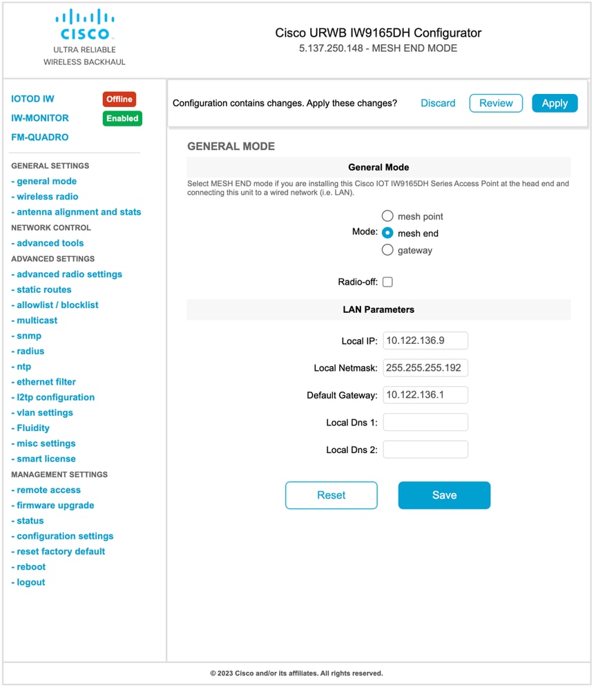
Once the parameters are configured, save the settings.
Wireless Radio
- Normally, for an IW9165, Radio 1 is configured for a point-to-point backhaul link as this is a directional internal antenna. For the use of only point-to-point applications, the second radio needs to be disabled.
- Both radios need to be configured with the same shared passphrase, frequency, and channel width.
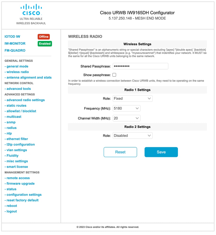
Once the page is configured, save the settings on both radios and apply the changes. This reboots the radios and the changes are then applied.
Monitoring the connectivity
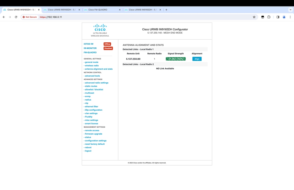
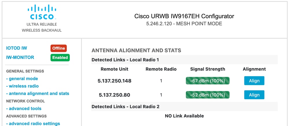
Once the radios come are back, the signal strength from the antenna alignment page can be checked. The recommended signal strength is between -45 dBm and -70 dBm.
It is important to validate that the signal strength from both ends of the point-to-point link with very close RSSI values.
Monitoring from FM Quadro
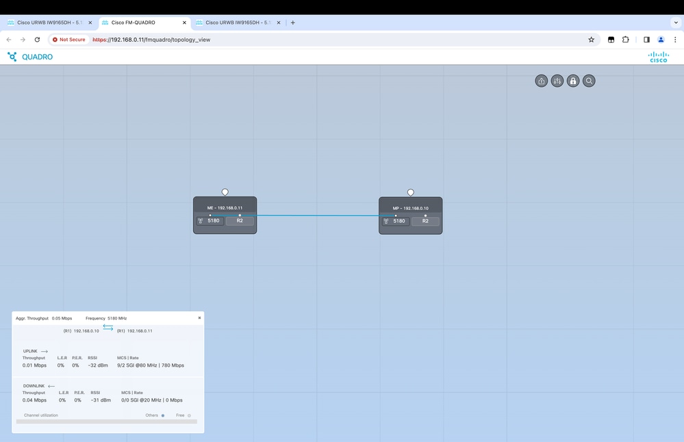
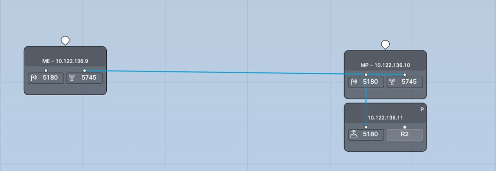
Further details of the link performance can be obtained from the FM-Quadro page. This provides real-time quality of the link including Link Error Rate (LER), Packet Error Rate (PER), RSSI, Throughput MCS, Spatial stream, Operating frequency, and so on.
Fluidity
The Cisco Fluidity (formerly Fluidmesh Fluidity) network architecture is based on Prodigy 2.0. This is a Multiprotocol Label Switching (MPLS)- based technology used to deliver IP-encapsulated data.
In a Cisco Ultra-Reliable Wireless Backhaul mobility network scenario, the handoff process can be assimilated to a network topology change in which an existing link is broken and a new link is created. However, industry-standard mechanisms to detect the change and reconfigure the nodes are too slow and data-intensive to provide adequate performance within a constrained real-time scenario (such as highspeed mobility). In particular, reconfiguration latency and the number of messages exchanged need to be minimized to reduce any chance of data packets being lost in the process. To mitigate the previously mentioned issues, Fluidity implements a fast handoff solution that provides very fast path reconfiguration, with latency in the order of one millisecond. The active mechanism is an extension of the network’s existing control plane and is based on a specific manipulation technique concerning the node MPLS FIB tables.
The Fluidity scheme allows mobile nodes and the client devices attached to them to maintain their IP address throughout the mobility process. In addition, all nodes are part of a single layer-2 mesh network.
Configuring Fluidity
Topology: Two IW9165D APs that are connected over wireless and IW9167 as a vehicle using Layer 2 Fluidity
- Like the point-to-point link, we need to configure the General mode page. Note that the cluster of a CURWB L2 fluidity network has only one Mesh end. As in this network, there is no fiber connectivity between the two IW9165D. They are connected through a point-to-point wireless backhaul link with radio interface 1. The mesh end for this small fluidity network is the IW9165D that is physically connected to the core network. All other radios in the cluster (including the vehicle) are then configured as a mesh point. In this topology, we have 1 mesh end and 1 mesh point that forms the point-to-point link and the IW 9167AP as a vehicle (configured as a mesh point).
- Radio 1 is configured for a point-to-point link and Radio 2 needs to be configured for Fluidity, for both trackside and vehicle radios. For vehicle radios, only one interface is configured with fluidity but the second radio is disabled.
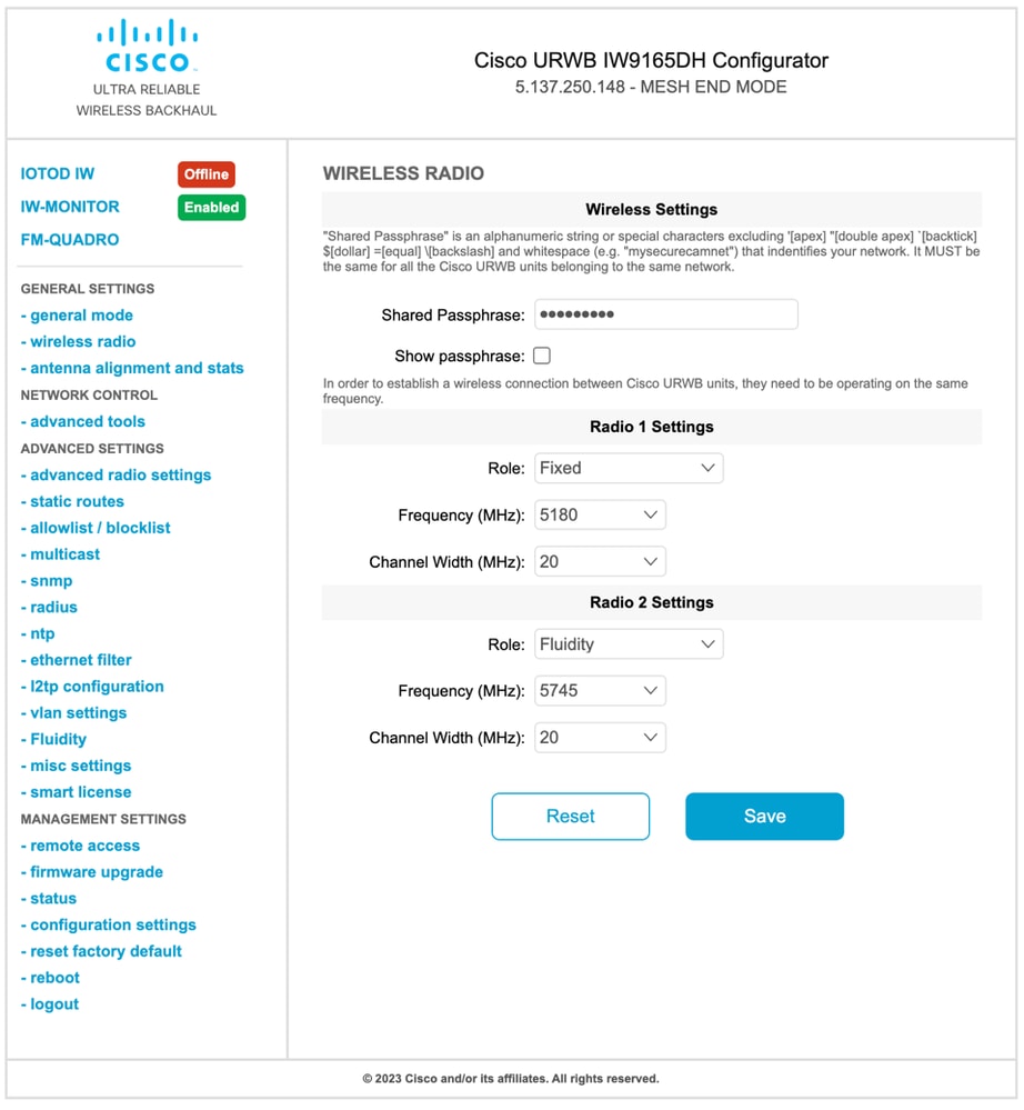
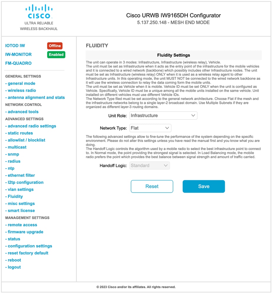
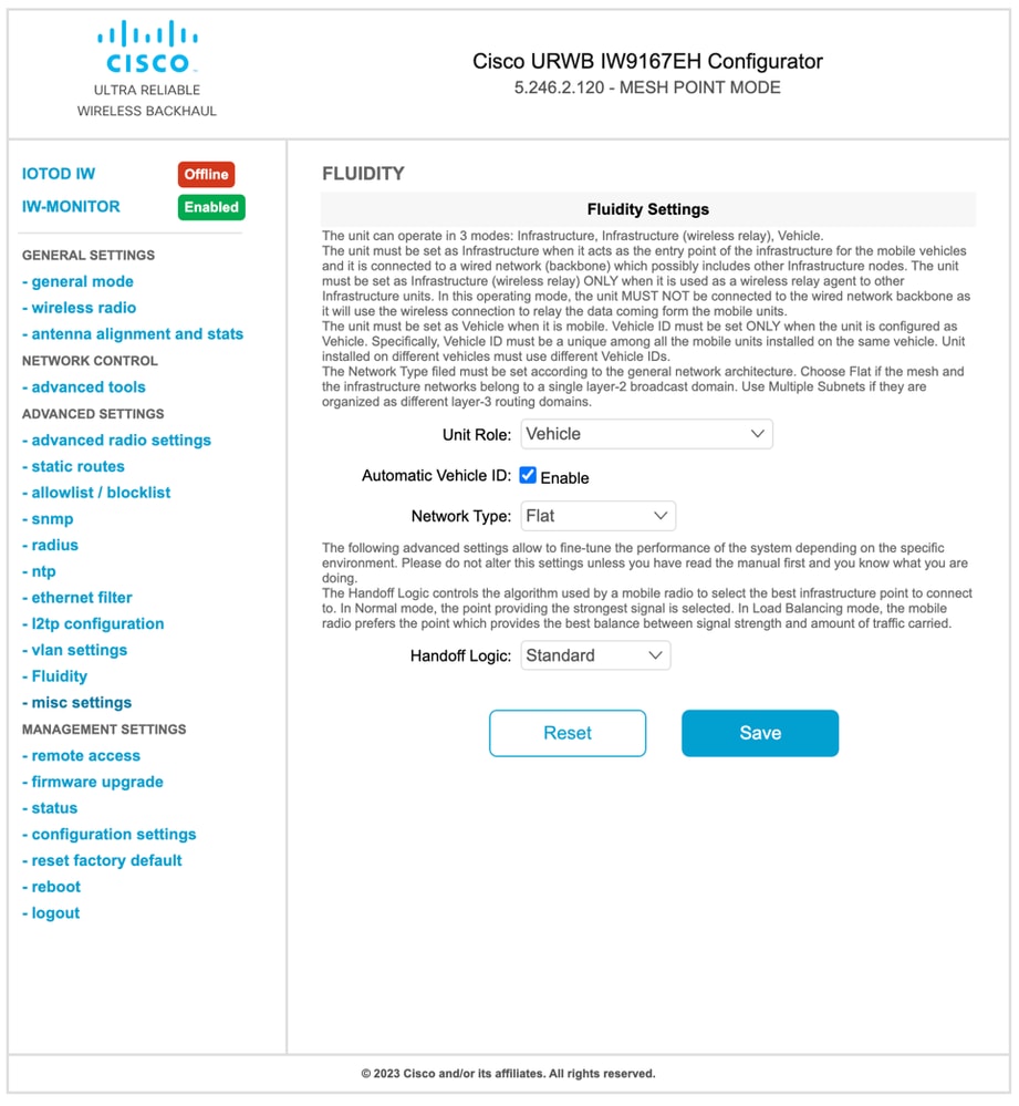
- From the Advanced Settings > Fluidity page, the trackside radios which provide coverage for the vehicles, need to be configured as Infrastructure. On the other side, the vehicle radio (IW 9167) needs to be configured as a vehicle.
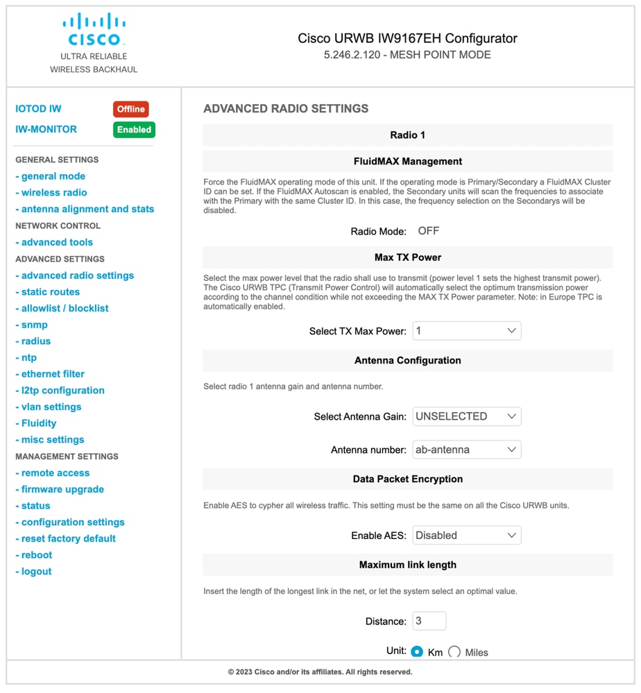
- If using 2x2 MIMO, select the antenna number as ab-antenna.
- For the IW 9167, if using 2x2 MIMO and are using interface 1, use antenna ports 3 & 4. If configured for interface 2, use antenna ports 5 & 6.
- After configuring every setting, save the configuration, and at the end, apply the changes. APs reboot and, once the radios are back online, we are able to check RSSI from the Antenna alignment page and monitor the live connectivity from the FM-Quadro page.


 Feedback