MSE Software Release 7.2 Virtual Appliance Configuration and Deployment Guide
Available Languages
Bias-Free Language
The documentation set for this product strives to use bias-free language. For the purposes of this documentation set, bias-free is defined as language that does not imply discrimination based on age, disability, gender, racial identity, ethnic identity, sexual orientation, socioeconomic status, and intersectionality. Exceptions may be present in the documentation due to language that is hardcoded in the user interfaces of the product software, language used based on RFP documentation, or language that is used by a referenced third-party product. Learn more about how Cisco is using Inclusive Language.
Contents
Introduction
Cisco Mobility Services Engine (MSE) Software Release 7.2 adds virtual appliance and support for VMware ESXi. This document provides configuration and deployment guidelines, as well as troubleshooting tips, for users that add the MSE virtual appliance to a Cisco Unified WLAN and that run Context-Aware Services and/or Cisco Adaptive Wireless Intrusion Prevention System (wIPS). In addition, this document describes the system requirements for MSE virtual appliance and provides general deployment guidelines for the MSE virtual appliance. This document does not provide configuration details for the MSE and associated components. This information is provided in other documents; references are provided.
Refer to the Related Information section for a list of documents about the configuration and design of Context Aware Mobility Services. Adaptive wIPS configuration is also not covered in this document.
Prerequisites
Requirements
There are no specific requirements for this document.
Components Used
The information in this document is based on the Cisco 3300 Series Mobility Services Engine.
The information in this document was created from the devices in a specific lab environment. All of the devices used in this document started with a cleared (default) configuration. If your network is live, make sure that you understand the potential impact of any command.
Conventions
Refer to Cisco Technical Tips Conventions for more information on document conventions.
Background Information
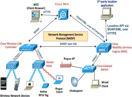
This image shows the typical Cisco WLAN deployment that includes Cisco Mobility Services Engine (MSE). This deployment also includes other wired/wireless network client, RFID tags, and a rogue access point (AP) and client. MSE provides visibility to these elements both for location and wIPS. Prior to MSE Software Release 7.2, only physical appliances were limited to MSE-3310 and MSE-3350/3355.
System Requirements
MSE Software Release 7.2 Virtual Appliance is supported and tested on VMware ESXi 4.1 and above. These server configurations have been tested and are recommended as a guideline.
-
Cisco Unified Computing System (UCS) C200 M2 Rack Mount Server
-
Two (2) Intel? Xeon? CPU E5506 @ 2.13GHz
-
RAM (as per level configured)
-
SAS drives with enhanced RAID controllers (minimum 500 GB+)
-
-
UCS C210 M2 Rack Mount Server
-
Two (2) Intel Xeon CPU E5640 @ 2.67GHz
-
RAM (as per level configured)
-
SAS drives with enhanced RAID controllers (minimum 500 GB+)
-
-
UCS C250 M2 Rack Mount Server
-
Two (2) Intel Xeon CPU E5570 @ 2.93GHz
-
RAM (as per level configured)
-
SAS drives with enhanced RAID controllers (minimum 500 GB+)
-
-
UCS C460 M2 Rack Mount Server
-
Two (2) Intel Xeon CPU E7-4830 @ 2.13GHz
-
RAM (as per level configured)
-
SAS drives with enhanced RAID controllers (minimum 500 GB+)
-
Note: Use two (2) quad-core processors that are at least as powerful as the ones mentioned above.
Management Software and VMware Licensing
Cisco MSE Software Release 7.2 virtual appliance supports ESX/ESXi 4.x and above.
In order to manage ESXi hosts and in order to configure and deploy the virtual appliances, Cisco recommends that you install vCenter Server 4.x on a Windows XP or Windows 7 64-bit machine and to obtain a vCenter Enterprise license. Alternatively, if you have only one ESXi host, you can use the vSphere client in order to manage it.
Resource Requirements
Resource requirements depend on the license you want to deploy. This table lists the different levels at which you can configure your virtual appliance:
| Primary MSE | Resources | Supported License (Individually) | ||
|---|---|---|---|---|
| Virtual Appliance Level | Total Memory | CPU | CAS License | wIPS License |
| Low | 6G | 2 | 2000 | 2000 |
| Standard | 11G | 8 | 18000 | 5000 |
| High | 20G | 16 | 50000 | 10000 |
Note: The suggested limits listed for the CAS and wIPS licenses are maximum supported limits when only one service is running. Co-existence limits apply if you want to run both services on the same appliance.
Setting Up the ESXi Host
Complete these steps in order to set up an MSE virtual appliance on a UCS or similar server:
-
Ensure your machine has at least 500 GB+ hard disk space and fast SAS drives with enhanced RAID controllers. (Use a block size of at least 4 MB when you create datastores for versions prior to ESXi 5.0.)
-
Install ESXi.
-
Insert the ESXi 4.1 or later install disc, and boot from the drive.
-
If you use multiple drives, install ESXi in the drive that is configured as the boot drive. The default user name is root, and the password is blank (no password).
Note: If you choose the wrong drive for installation, you can reformat using a Fedora Live CD.
-
-
Configure the IP address.
Choose network adapters that are enabled and active. You might have multiple network adapters if your host is connected to multiple networks. You can set the same IP address during CIMC setup; press F8 during boot up to set the IP address. Also, change the default password.
Once ESXi is set up, you can use a Windows XP or Windows 7 machine, along with the IP address and login credentials configured above, in order to connect to the ESXi host through the vSphere client.
Refer to
Licensing ESX 4.x, ESXi 4.x, and vCenter Server 4.x
![]() for
information about licensing the ESXi host.
for
information about licensing the ESXi host.
Refer to these articles for information on how to set up datastores on ESXi:
 Warning: Use a block size of at least 4 MB when you create datastores for
ESXi 4.1.
Installing the MSE Virtual Appliance
MSE virtual appliance is distributed as an Open Virtual Appliance (OVA) image that can be deployed on an ESXi host using the vSphere client. There are two available OVA versions: one version is for a demo image, which requires only 60GB of disk space, and the other version is a generic production image.
The production image distributable assumes a minimum of 500 GB and above of available disk space on the ESXi host datastore. The OVA can be selected and deployed through the vSphere client. Choose File > Deploy OVF Template in order to deploy the template.
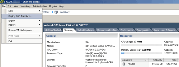
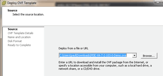
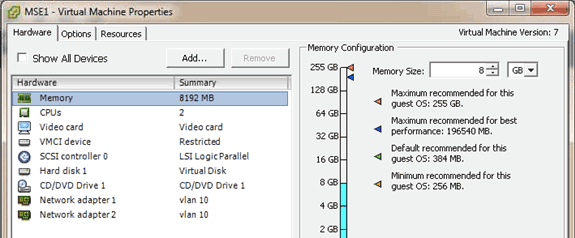
The image takes a few minutes to deploy depending on network speed. Once deployed, you can edit the virtual machine (VM) configuration in order to configure the appliance; the VM should be powered off when configured.
Configuring the MSE Virtual Appliance Levels
The table in this section lists the levels configurable on the virtual appliance and the corresponding resource requirements. Allocate dedicated cores to the appliance and not the hyper-threaded virtual cores, as it will affect performance if you assume the host has more virtual cores and you deploy more appliances. For example, in the UCS C200 mentioned above, there are eight (8) physical cores available but sixteen (16) virtual cores with hyper-threading. Do not assume sixteen (16) cores are available; allocate only eight (8) cores in order to ensure MSE performs reliably when stressed.
| Primary MSE | Resources | Supported License(Individually) | Supported Secondary MSE | ||||
|---|---|---|---|---|---|---|---|
| Virtual Appliance Level | Total Memory | CPU | CAS License | wIPS License | Virtual Appliance | Physical Box | |
| Low | 6G | 2 | 2000 | 2000 | Low+ | Not Supported | |
| Standard | 11G | 8 | 18000 | 5000 | Standard+ | ||
| High | 20G | 16 | 50000 | 10000 | High+ | ||
Setting Up the MSE Virtual Appliance
Once the virtual appliance has been deployed and configured, you can power it up. When the appliance is powered up for the first time, you will need to enter the default login credentials: root/password.
When you first log in, the appliance begins configuration of the MSE software and also installs the Oracle database. This is a one-time, time-consuming process, which will take at least 30-40 minutes. Once installation is complete, the login prompt is displayed again. Refer to the Configuring the Mobility Services Engine section of the Cisco 3355 Mobility Services Engine Getting Started Guide in order to continue configuring the appliance.
Configuring the Network
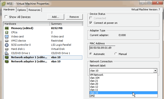
By default, VMs use the host network settings; therefore, you are not required to configure the VM adapters on ESXi. However, if you have both public and private networks connected to the host and you want the VMs to have access to both, you can configure the VM adapters in the vShpere Client.
In the vSphere Client, select the host, click the Configuration tab, and then click Networking. You can view the physical adapters in the Virtual Switch properties.
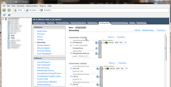
Create separate switches with separate adapters in order to isolate the networks. Then, you can assign the VM adapters to these networks as required.
Adding Hard Disk Space
If required, add additional disk capacity to the VM and expand the partitions.
Note: The installDrive.sh script (located in the /opt/mse/framework/bin directory) detects new drives and repartitions existing partitions in order to use and extend the new drives.
Make sure you back up your VM (or at least the MSE data) before you attempt to repartition the disk space.
In order to add more disk space to your VM, shut down the VM, go to the VM settings, and add the additional hard disk.
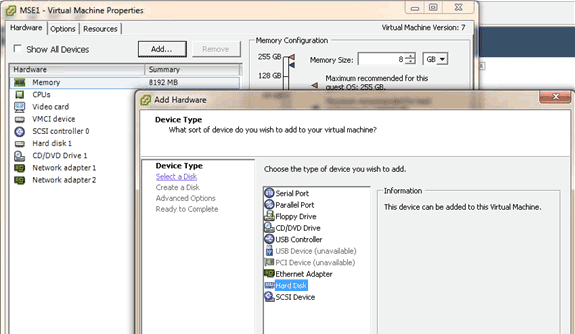
Once the hard disk has been added, power on the VM, log in to the appliance, and run the installDrive.sh script. The script should mount and repartition the newly added drive. If you added multiple hard drives, run the script once for each new drive.
Block Size
For ESXi versions prior to 5.0, Cisco recommends that the datastore on the host has a block size of 4 MB or more; otherwise, the deployment of the OVA might fail. If deployment fails, you can reconfigure the block size.
In order to reconfigure the block size, go to the ESX host Configuration > Storage > Delete the datastores, and add the storage again to the new datastores with a block size of at least 4MB.

VMware Tools
If the VM throws the following error, right-click the VM in the vSphere Client, and choose Guest > Install/Upgrade VMware Tools in order to install or upgrade the VMware tools:
Guest OS cannot be shutdown because Vmware tools is not installed or running.
Upgrading the Virtual Appliance
Once you have configured the virtual appliance, it should be treated like a physical MSE box. You do not need to deploy a new OVA every time you want to upgrade to the latest MSE release; you can download the appropriate installer image onto the appliance and follow steps for upgrade as you would with a physical appliance.
Licensing the Virtual Appliance
Once you have configured the virtual appliance, it can be used in the evaluation mode (default 60 days) without licensing the appliance. However, you must activate the virtual appliance using a virtual appliance activation license if you plan to deploy permanent licenses or use features like High Availability (HA). You can get the Unique Device Identifier (UDI) from the virtual appliance (run show csludi on the appliance) or from the Cisco Prime Network Control System (NCS) MSE General Properties and use this information to purchase the virtual appliance activation license and permanent service licenses.
This image shows recent changes to the License Center UI for the virtual appliance.
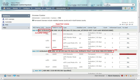
For the virtual appliance, a message next to the MSE name clearly indicates whether or not it is activated. In addition, there are two limit columns: the Platform Limit column lists the maximum supported license for that service on this appliance (depending on the resource allocation to the VM), and the Installed Limit column lists the actual license installed or that is available through evaluation on the appliance.
High Availability on the Virtual Appliance
In order to use the HA feature, both the primary and secondary appliances must be activated with a virtual appliance activation license.
Configure High Availabiltiy
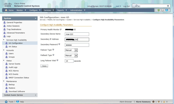
You can set up the HA configuration through the primary MSE on the NCS.
Activating the Secondary MSE
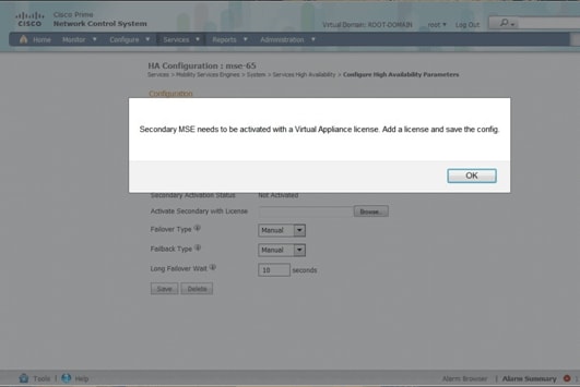
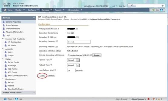
The secondary appliance must be activated. You can use the UDI information in order to request an activation license for the secondary MSE. On the HA Configuration page, browse for the license, and click Save. HA will be set up once the secondary MSE is successfully activated.
Deactivating the Secondary MSE
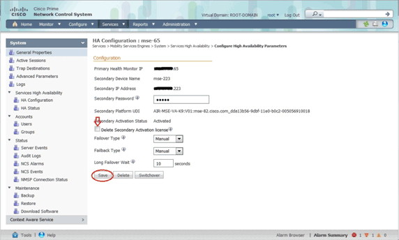
In case you need to delete the activation license from the secondary MSE, you can click the check box, and click Save in order to deactivate the secondary MSE.
Virtual Appliance on ESXi 5.0
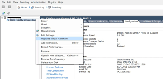
On the ESXi 5.0, the block size is fixed at 1 MB as it supports large VM deployments. In order to be able to assign more than eight (8) cores to the virtual appliance, you must upgrade the virtual hardware. In order to upgrade the virtual hardware, select the MSE, and choose Upgrade Virtual Hardware as shown in this image:
MSE Console Procedure
-
Log in to the console with these credentials: root/password.
Upon the initial boot up, the MSE prompts the administrator to launch the setup script.
-
Enter yes to this prompt.
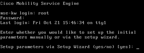
Note: If the MSE does not prompt for setup, enter the following command: /opt/mse/setup/setup.sh.
-
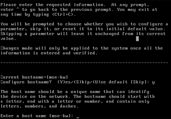
Configure the host name:
-
Configure the DNS domain name:

-
Configure the primary HA role:

-
Configure Ethernet interface parameters:

-
When prompted for eth1 interface parameters, type Skip in order to proceed to the next step as a second NIC is not required for operation.

Note: The address configured must provide IP connectivity to the perspective WLCs and WCS Management System used with this appliance.
-
Enter DNS server(s) information. Only one DNS server is required for successful domain resolution, enter backup servers for resiliency.

-
Configure the time zone. Cisco recommends that you use UTC (coordinated universal time).
If the default time zone of New York is not applicable to your environment, browse through the location menus in order to select the correct time zone.

-
When prompted to configure future restart day and time, type Skip.

-
Configure remote syslog server if applicable.

-
Configure the Network Time Protocol (NTP) or system time.
NTP is optional but ensures your system maintains an accurate system time. If you choose to enable NTP, the system time will be configured from NTP servers that you select. Otherwise, you will be prompted to enter the current date and time.

-
When prompted to configure the login banner, type Skip.

-
Enable local console root login.
This parameter is used to enable/disable local console access to the system. Local console root login should be enabled so that local troubleshooting can occur. The default value is Skip.

-
Enable Secure Shell (SSH) root login.
This parameter is used to enable/disable remote console access to the system. The SSH root login should be enabled so that remote troubleshooting can occur. However, corporate security policies might require that this option be disabled.

-
Configure single user mode and password strength.
These configuration parameters are not required; the default value is Skip.

-
Change the root password.
This step is critical in ensuring system security. Be sure to pick a strong password that consists of letters and numbers with no dictionary words. The minimum password length is eight (8) characters. Default credentials are root/password.

-
Configure login and password related parameters:

-
Configure a boot password (Grub) password. (Optional)
This configuration parameter is not required. The default is Skip.

-
Configure the NCS communication username.

-
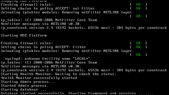
Accept the change to the configuration.

This image shows an example of the completion screen:
-
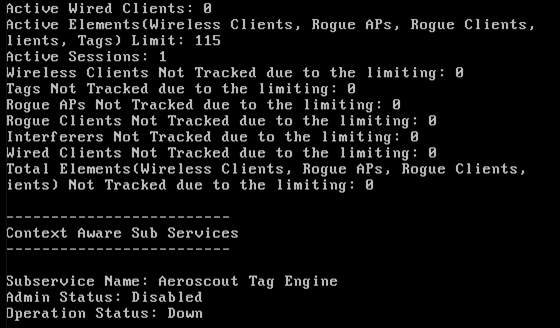
Run the getserverinfo command in order to verify the configuration.
Adding MSE VA to NCS
-
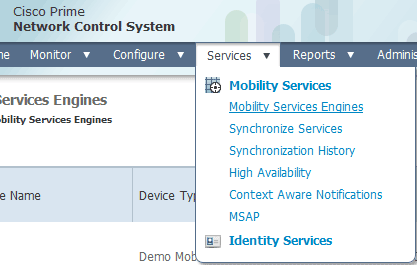
Log in to the NCS, and choose Services > Mobility Services Engines.
-
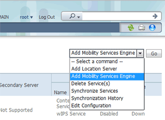
From the drop-down list located on the right side of the page, choose Add Mobility Services Engine, and click Go.
-
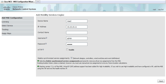
Enter a unique device name for the MSE, the IP address previously configured during the MSE setup, a contact name for support. and the NCS username and password configured during the MSE setup.
Do not change the username from the default of admin. You can leave as default.
-
Click Next.
-
Click Licensing, and verify the licensing. At install, the default demo license is sufficient for testing. You can add more purchased license(s) or remove license(s) on the Licensing page.
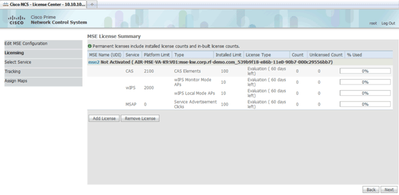
-
Click Next.
-
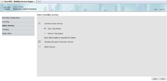
On the Select Mobility Service page, click the Cisco Tag Engine (available since 7.0MR) radio button (for client and RFID tag support), or click the Partner Tag Engine radio button (for Aeroscout, etc.).
-
Click the Wireless Intrusion Protection Service check box in order to test the wIPS security feature of Monitor Mode and Enhanced Local Mode features.
-
Click Next.
-
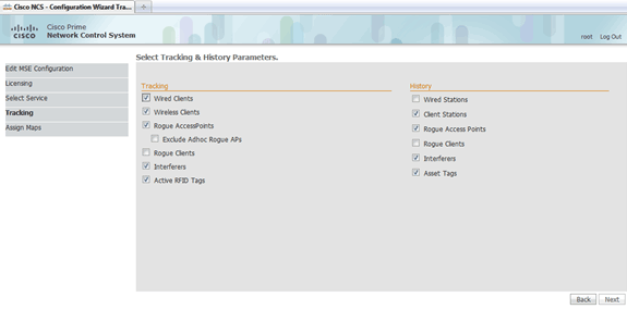
Check the check boxes for elements to be enabled for tracking and for history parameters for those elements to be available for historical reporting.
-
Click Next.
-
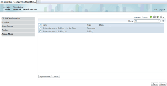
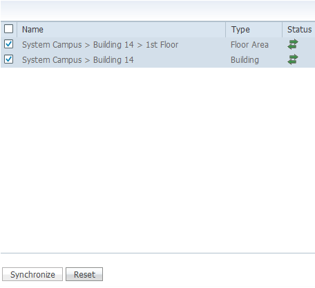
Check the check boxes for the existing building and floor, and click Synchronize.
Once synchronized, the Status column updates to show that the initial network design has been synchronized.
-
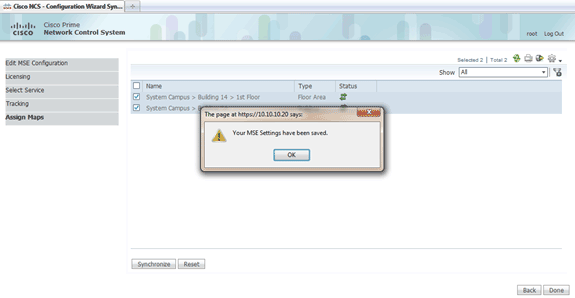
When synchronization is complete, click Done.
A dialog box appears that states the MSE settings have been saved.
-
Confirm the configuration on the main MSE page of the NCS.

Make sure to synchronize the rest of the network designs, controllers, wired switches, and event groups as available.
Note: The Cisco Context-Aware service is highly dependent on a synchronized clock between the WLC, NCS, and MSE. If all three of these systems are not pointed to the same NTP server and configured with the same time zone settings, the Context-Aware service will not function correctly. Before you attempt any troubleshooting procedures, ensure the system clock is the same on all components of the Context-Aware system.
-
Check MSE and controller communication for chosen services.
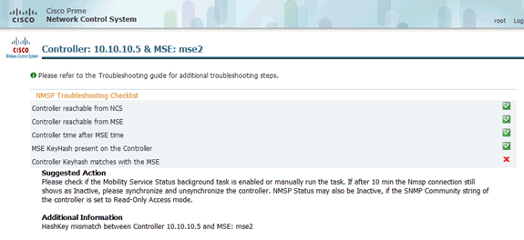
Verify that the MSE is communicating with each of the controllers for only the chosen service; Network Mobility Service Protocol (NMSP) status must be active.
This image provides an example of when the keyhash is not added to the WLC.
On WLC console, use the show auth-list command.
The following example shows from WLC console that there is no location server available:

In order to manually add the MSE and establish a NMSP connection to WLC, complete these steps:
-
On the MSE console, run the cmdshell command, and then the show server-auth-info command.
This example shows the MAC address and the keyhash to be used for adding to the WLC.

-
Run the config auth-list add ssc <mac address> <MSE keyhash> command, and then run the show auth-list.
This example shows that the MSE was added to the WLC (manually).

-
On the NCS, confirm that the NMSP connection shows Active.

-
Command Line Reference
WLC Commands
config location expiry ?
client         Timeout for clients
calibrating-client Timeout for calibrating clients
tags           Timeout for RFID tags
rogue-aps      Timeout for Rogue APs
show location ap-detect ?
all            Display all (client/rfid/rogue-ap/rogue-client) information
client         Display client information
rfid           Display rfid information
rogue-ap       Display rogue-ap information
rogue-client   Display rogue-client information
(Cisco Controller) >show location ap-detect client
show client summary
Number of Clients................................ 7
MAC Address       AP Name           Status        WLAN/Guest-Lan Auth Protocol Port Wired
----------------- ----------------- ------------- -------------- ---- -------- ---- -----
00:0e:9b:a4:7b:7d AP6               Probing       N/A            No   802.11b  1    No
00:40:96:ad:51:0c AP6               Probing       N/A            No   802.11b  1    No
(Cisco Controller) >show location summary
 Location Summary
 Algorithm used:                 Average
 Client
        RSSI expiry timeout:     5 sec
        Half life:               0 sec
        Notify Threshold:        0 db
 Calibrating Client
        RSSI expiry timeout:     5 sec
        Half life:               0 sec
 Rogue AP
        RSSI expiry timeout:     5 sec
        Half life:               0 sec
        Notify Threshold:        0 db
 RFID Tag
        RSSI expiry timeout:     5 sec
        Half life:               0 sec
        Notify Threshold:        0 db
show rfid config

RFID Tag data Collection......................... Enabled
RFID  timeout.................................... 1200 seconds
RFID mobility.................................... Oui:00:14:7e : Vendor:pango  State:Disabled
show rfid detail <mac address>

RFID address.....................................00:0c:cc:7b:77:3b
Vendor........................................... Aerosct
Last Heard....................................... 7 seconds ago
Packets Received................................. 40121
Bytes Received................................... 2567744
Detected Polling Interval........................ 30 seconds
Cisco Type.......................................

Content Header
=================
CCX Tag Version.................................. 1
Tx Power......................................... 18 dBm
Channel.......................................... 11
Reg Class........................................ 6
Burst Length..................................... 1

CCX Payload
===========
Last Sequence Control............................ 0
Payload length................................... 29
Payload Data Hex Dump
00 02 00 33 02 07 42 00 00 00 00 00 00 03 05 01
41 bc 80 00 04 07 00 0c cc 00 00 00 00 d

Nearby AP Statistics:

      demo-AP1260(slot 0, chan 11) 6 seconds .... -48 dBm
show location plm
Location Path Loss Configuration
Calibration Client : Enabled   , Radio: Uniband
Normal Clients : Disabled      , Burst Interval: 60

(Cisco Controller) >config location ?
plm            Configure Path Loss Measurement (CCX S60) messages
algorithm      Configures the algorithm used to average RSSI  and SNR values
notify-threshold Configure the LOCP notification threshold for RSSI measurements
rssi-half-life Configures half life when averaging two RSSI readings
expiry         Configure the timeout for RSSI values
config location expiry client ?
<seconds>      A value between 5 and 3600 seconds
config location rssi-half-life client ?
<seconds>      Time in seconds (0,1,2,5,10,20,30,60,90,120,180,300 sec)
show nmsp subscription summary
Mobility Services Subscribed:
Server IP                Services
---------                --------
172.19.32.122            RSSI, Info, Statistics, IDS
MSE Commands
Run this command in order to determine the status of MSE services:
[root@MSE ~]# getserverinfo
Run this command in order to start the context-aware engine for client tracking:
[root@MSE ~]# /etc/init.d/msed start
Run this command in order to determine the status of the context-aware engine for client tracking:
[root@MSE ~]# /etc/init.d/msed status
Run this command in order to stop the context-aware engine for client tracking:
[root@MSE ~]# /etc/init.d/msed stop
Run this command in order to perform diagnostics:
[root@MSE ~]# rundiag
Note: The rundiag command can also be used to view MSE UDI information that is required in order to obtain the license file for context-aware engine for clients.
Related Information
Contact Cisco
- Open a Support Case

- (Requires a Cisco Service Contract)
 Feedback