Introduction
This document describes the VLAN configuration on Industrial Wireless (IW) Access Points so they can pass tagged traffic over Wireless.
Background Information
Cisco Ultra-Reliable Wireless Backhaul (CURWB) lets you connect remote buildings both fixed or moving assets to your network.
It provides a high data rate, ultra-low latency and packet loss, and seamless handoffs.
Prerequisites
If you want to send VLAN traffic over wireless, the VLAN feature needs to be activated on all the Access Points in the cluster.
The VLAN feature is used to receive and transmit packets with VLAN tags on the radios.
This is not a default feature and requires the designated radios to have an FM-VLAN license installed and activated.
Once the VLAN feature is enabled, the user can edit two different settings on the radio:
- Management VLAN
- Native VLAN
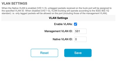
VLAN Settings
- Management VLAN: The Management VLAN ID is the VLAN identity tag at which the radio can be accessed to make control plane changes. The management VLAN facilitates administrative access to the radio through the GUI & CLI. The default value of Management VLAN ID is ‘1’, and can be changed.
- Native VLAN: Incoming untagged packets are tagged with this VLAN number.
- Default: 1
- If configured as “0”, the incoming untagged packets are dropped.
- If the radio is configured to be in “mesh end” mode, the incoming packets tagged with the configured native VLAN tag are forwarded untagged.
Configuration Steps
- Activate VLAN feature on the IW radios. Note: With IW licensing model all features (except bandwidth) are available out of the box.
- Navigate to VLAN tab of the GUI to configure the Management VLAN and Native VLAN.
- Set the Management VLAN ID.
- Set the Native VLAN ID. The radio uses it to tag untagged packet. If it is set to 0, the radio just drops all untagged packets.
The VLAN configuration is the same on all radios in the cluster and, by default, Management and Native VLANs are set to 1. You can also configure smart VLAN from the CLI and the process is as follows:
CLI configuration
#configure vlan management X (where X is an integer from 1 to 1024 and represents the Management Vlan ID)
#configure vlan native Y (where Y is an integer from 1 to 1024 and represents the Native Vlan ID)
#write (to save the configuration)
#reload (to reboot the radio and apply the changes)
Note: Both management and native VLANs can be configured to be the same.
Native & Management VLAN Scenarios
This image depicts three scenarios where the radios forward VLAN tags and how the native VLAN works.
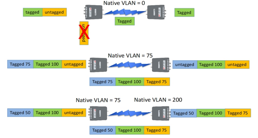
Scenario 1: If the native VLAN on the radio is set to 0, any untagged traffic is dropped by the radio as the radio receives the packet.
Scenario 2: If the native VLAN on both the CURWB radios is set to VLAN 75 and the incoming traffic has VLAN 100 and untagged traffic, the untagged traffic goes over the CURWB radio after it gets tagged by CURWB radio's own native VLAN. However, after leaving the CURWB radios and entering the corporate network, VLAN tags of all VLAN 75 traffic is stripped off. After which, there is only the tagged VLAN 100 and untagged traffic.
Scenario 3: If the native VLAN of CURWB radio needs to be tagged permanently so even after it leaves the radio and enters the corporate network with VLAN 200, then remote CURWB radio needs to have a VLAN other than VLAN 200. In this example, the Mesh End has a Native VLAN of 75, and the Mesh Point with a native VLAN of 200. For Untagged traffic originating from the mesh point side, it is tagged as VLAN 200, arriving at the Mesh End the native VLANs do not match causing it to be tagged permanently as VLAN 200 into the corporate network.
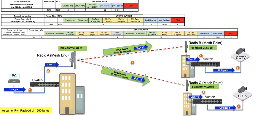
CURWB Management VLAN & MPLS encapsulation
This image is a common Point to Multipoint architecture. On the left, we have a Mesh-End radio connected to a VLAN-tagged Layer 2 network. CURWB preserves Layer 2 within our Prodigy protocol (shown as note 3) and adds the additional MPLS headers and VLAN tags to the datagram, then sends the data over the air to the Mesh-Point radios on the right. At the receiving Mesh Point side, the MPLS and Management headers are stripped, and the data is presented as the usual tagged Ethernet traffic on the other side.
VLAN configuration in a lab setup
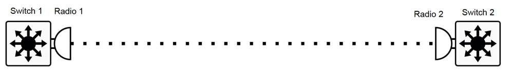
Here is a sample lab configuration for reference.
SWITCH 1 CONFIG
Switch1#show cdp neighbors
Capability Codes: R - Router, T - Trans Bridge, B - Source Route Bridge
S - Switch, H - Host, I - IGMP, r - Repeater, P - Phone
Device ID Local Intrfce Holdtme Capability Platform Port ID
MP_TRK_Backhaul Gig 0/23 121 R T IW9165DH- Gig 0
Switch1#show ip interface brief
Interface IP-Address OK? Method Status Protocol
Vlan1 unassigned YES NVRAM administratively down down
Vlan500 192.168.6.100 YES manual up up
Vlan581 10.122.136.1 YES NVRAM up up
GigabitEthernet0/23 unassigned YES unset up up
Switch1#show interfaces trunk
Port Mode Encapsulation Status Native vlan
Gi0/23 on 802.1q trunking 1
Port Vlans allowed on trunk
Gi0/23 500,581
Port Vlans allowed and active in management domain
Gi0/23 500,581
Port Vlans in spanning tree forwarding state and not pruned
Gi0/23 500,581
Switch1#show running-config interface g0/23
Building configuration...
Current configuration : 137 bytes
!
interface GigabitEthernet0/23
switchport trunk encapsulation dot1q
switchport trunk allowed vlan 500,581
switchport mode trunk
end
RADIO 1 CONFIG:
Radio1#show ip
IP: 10.122.136.9
Network: 255.255.255.192
Gateway: 10.122.136.1
Nameservers: 64.102.6.247
Radio1#show vlan
VLAN status: enabled
Management VID: 581
Native VID: 0
RADIO 2 CONFIG:
Radio2#show ip
IP: 10.122.136.15
Network: 255.255.255.192
Gateway: 10.122.136.1
Nameservers: 64.102.6.247
Radio2#show vlan
VLAN status: enabled
Management VID: 581
Native VID: 0
SWITCH 2 CONFIG
Switch2#show cdp neighbors
Capability Codes: R - Router, T - Trans Bridge, B - Source Route Bridge
S - Switch, H - Host, I - IGMP, r - Repeater, P - Phone,
D - Remote, C - CVTA, M - Two-port Mac Relay
Device ID Local Intrfce Holdtme Capability Platform Port ID
Radio2 Gig 1/0/3 135 R T IW9165DH- Gig 0
Switch2#show ip interface brief
Interface IP-Address OK? Method Status Protocol
Vlan1 unassigned YES NVRAM administratively down down
Vlan500 192.168.6.101 YES NVRAM up up
Vlan581 10.122.136.35 YES NVRAM up up
GigabitEthernet1/0/3 unassigned YES unset up up
Switch2#show interface trunk
Port Mode Encapsulation Status Native vlan
Gi1/0/3 on 802.1q trunking 1
Port Vlans allowed on trunk
Gi1/0/3 500,581
Port Vlans allowed and active in management domain
Gi1/0/3 500,581
Port Vlans in spanning tree forwarding state and not pruned
Gi1/0/3 500,581
Switch2#show running-config interface Gi1/0/3
Building configuration...
Current configuration : 100 bytes
!
interface GigabitEthernet1/0/3
switchport trunk allowed vlan 500,581
switchport mode trunk
end
With this configuration, VLAN 500 can communicate over wireless. Now it is important to note that while configuring VLAN on a Layer 2 network, Layer 3/multiple subnet fluidity cannot be configured.
 Feedback