Cisco Application Policy Infrastructure Controller Enterprise Module Deployment Guide, Release 1.1.x
Bias-Free Language
The documentation set for this product strives to use bias-free language. For the purposes of this documentation set, bias-free is defined as language that does not imply discrimination based on age, disability, gender, racial identity, ethnic identity, sexual orientation, socioeconomic status, and intersectionality. Exceptions may be present in the documentation due to language that is hardcoded in the user interfaces of the product software, language used based on RFP documentation, or language that is used by a referenced third-party product. Learn more about how Cisco is using Inclusive Language.
- Updated:
- February 29, 2016
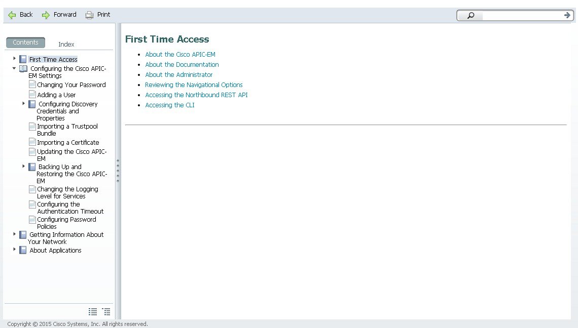
Chapter: Configuring the Cisco APIC-EM Settings
- Logging into the Cisco APIC-EM
- Quick Tour of the APIC-EM Graphical User Interface (GUI)
- Configuring the Prime Infrastructure Settings
- Discovery Credentials
Configuring the Cisco APIC-EM Settings
- Logging into the Cisco APIC-EM
- Quick Tour of the APIC-EM Graphical User Interface (GUI)
- Configuring the Prime Infrastructure Settings
- Discovery Credentials
- Security
- Enabling EasyQoS
- Updating the Cisco APIC-EM Software
- Backing Up and Restoring the Cisco APIC-EM
- Service Logs
- Configuring the Authentication Timeout
- Configuring Password Policies
- Telemetry Collection
- Configuring the Proxy
Logging into the Cisco APIC-EM
You access the Cisco APIC-EM GUI by entering the IP address that you configured for the network adapter using the configuration wizard. This IP address connects to the external network. Enter the IP address in your browser in the following format:
https://IP address
Quick Tour of the APIC-EM Graphical User Interface (GUI)
For a quick introduction to the Cisco APIC-EM GUI, log into the Cisco APIC-EM controller as an administrator and follow the procedure below.
What to Do Next
If you are using the IWAN application with Cisco Prime Infrastructure for your network, then proceed to configure your Prime credentials. If you are not using the IWAN application with Cisco Prime Infrastructure, then proceed to configure the discovery credentials for your network.
Configuring the Prime Infrastructure Settings
You can enter and save your Cisco Prime Infrastructure (PI) settings to the Cisco APIC-EM using the controller's UI. These PI settings are used by the IWAN application to establish an authenticated connection between the controller and PI server, after a request initiated by the controller. The IWAN application uses the authenticated connection to perform its centralized network management and enforcement duties with PI data.
You can configure the PI settings using the Prime Infrastructure Settings window in the Cisco APIC-EM GUI.
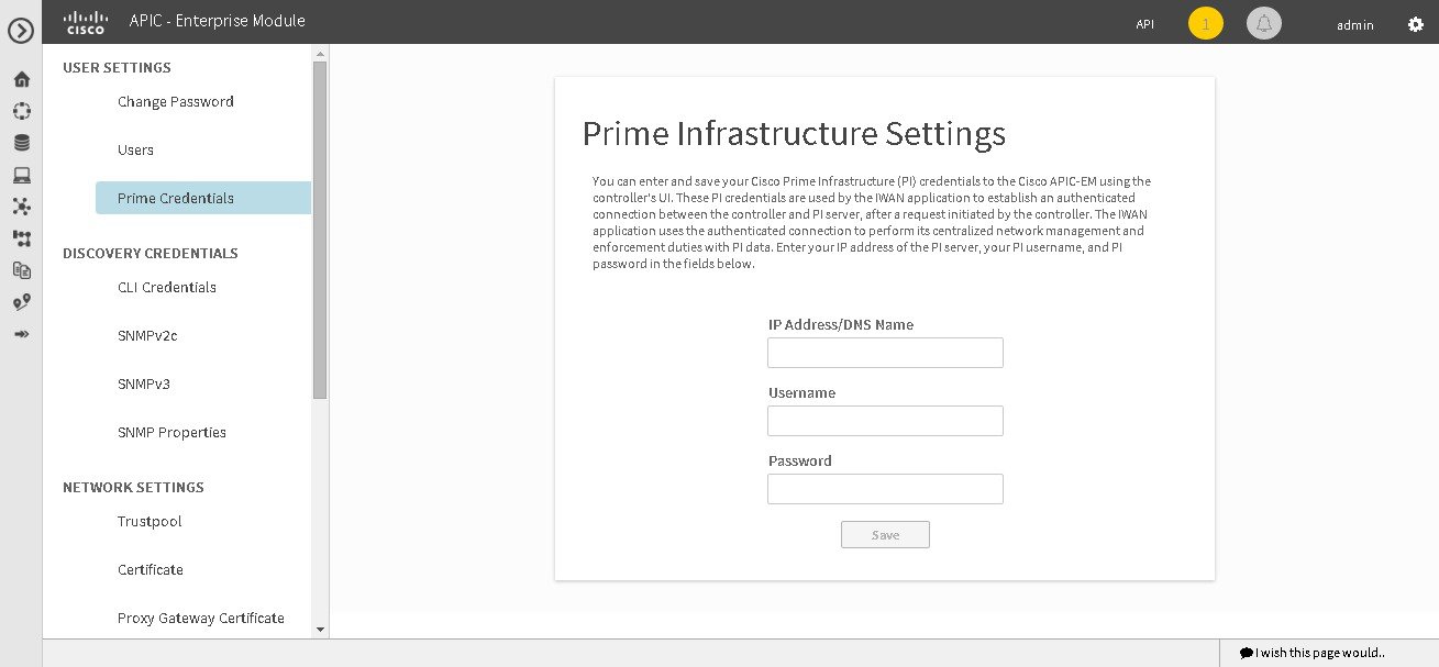
You must have successfully deployed the Cisco APIC-EM and it must be operational.
You must have administrator (ROLE_ADMIN) permissions to perform this procedure.
For information about the user permissions required to perform tasks using the Cisco APIC-EM, see the chapter, Managing Users and Roles in the Cisco Application Policy Infrastructure Controller Enterprise Module Configuration Guide.
What to Do Next
Proceed to configure the discovery credentials for your network.
Discovery Credentials
The Cisco APIC-EM supports two different types of discovery credentials: global and discovery request-specific (request-specific). Both types of discovery credentials can consist of CLI or SNMP credentials that are configured using the controller's GUI.
The global credentials (CLI and SNMP) are configured in the Discovery Credentials windows as described in this chapter. These global credentials are used in addition to any request-specific credentials that are configured in the Discovery window. For information about the procedure to configure request-specific credentials in the Discovery window, see the Cisco Application Policy Infrastructure Controller Enterprise Module Configuration Guide.
Both CLI and SNMP credentials are required for a successful discovery. The SNMP credentials (either global or request-specific) are used for device discovery. The CLI credentials (either global or request-specific) are used for capturing device configurations for the controller's inventory.
You should enter at least one set of SNMP credentials, either SNMPv2c or SNMPv3, for your device discovery. If you are going to configure SNMPv2 settings in your network, then SNMP Read Only (RO) community string values should be entered in the controller to assure a successful discovery and populated inventory. However, if an SNMP RO community string is not entered into the controller, as a best effort, discovery will run with the default SNMP RO community string "public."
 Note | You can enter values for both SNMP versions (SNMPv2c and SNMPv3) for a single discovery. The controller supports multiple SNMP credential configurations. Altogether, you can enter a maximum of 5 global device credentials (SNMP or CLI) using the Discovery Credentials windows as described in this chapter, with an additional credentials set being created in the Discovery window. Therefore, for a single discovery scan request, you can configure a total of 6 credential sets of each type (CLI or SNMP). |
- Global Credentials
- Discovery Request-Specific Credentials
- Discovery Credentials Example
- Discovery Credentials Rules
- Discovery Credentials Caveats
- Configuring CLI Credentials—Global
- Configuring SNMP
Global Credentials
Global credentials are defined as preexisting credentials that are common to the devices in a network. Global credentials (CLI and SNMP) are configured on the devices using the GUI (Discovery Credentials) and permit successful login to the devices. Global credentials are used by the Cisco APIC-EM to authenticate and access the devices in a network that share this device credential when performing network discoveries.
You configure the global CLI credentials in the CLI Credentials window. You access this window, by clicking either admin or the Settings icon (gear) on the menu bar at the upper right of the screen. You then click the Settings link from the drop-down menu and then click CLI Credentials on the Setting Navigation pane.
You configure the global SNMP credentials in the SNMPv2c or SNMPv3 window . You access these windows, by clicking either admin or the Settings icon (gear) on the menu bar at the upper right of the screen. You then click the Settings link from the drop-down menu and then click one of the SNMP window links on the Setting Navigation pane.
Note | Multiple credentials can be configured in the CLI Credentials window. |
Discovery Request-Specific Credentials
Discovery request-specific credentials (request-specific credentials) are defined as preexisting device credentials for a specific network device or set of devices that do not share the global credentials.
You configure the request-specific credentials in the Discovery window prior to performing a discovery that is exclusive for that set of network devices. You access this window by clicking Discovery on the Navigation pane.
Discovery Credentials Example
The following example describes how a user would configure and run a series of discoveries to authenticate and access all of the devices in a network by the Cisco APIC-EM.
Assume a network of 20 devices that form a CDP neighborship. In this network, 15 devices share a global credential (Credential-0) and the 5 remaining devices each have their own unique or discovery request-specific credentials (Credential 1- 5).
To properly authenticate and access the devices in this network by the Cisco APIC-EM, you perform the following tasks:
-
Configure the CLI global credentials as Credential-0 for the controller.
You configure the global credentials in the CLI Credentials window. You access this window, by clicking either admin or the Settings icon (gear) on the menu bar at the upper right of the screen. You then click the Settings link from the drop-down menu and then click CLI Credentials on the Setting Navigation pane.
-
Configure the SNMP (v2c or v3) global credentials.
You configure these global credentials in the two SNMP windows. You access these GUI windows by clicking the Settings button at the top right and then clicking SNMPv2c or SNMPv3 on the Setting Navigation pane.
-
Run a CDP discovery using one of the 15 device IP addresses (15 devices that share the global credentials) and selecting the global credentials in the GUI. You run a CDP discovery in the Discovery window. You access this window, by clicking Discovery on the Navigation pane.
-
Run 5 separate Range discoveries for each of the remaining 5 devices using the appropriate discovery request-specific credentials and SNMP values (for example, Credential-1, Credential-2-5, etc.).
You configure the discovery request-specific credentials in the Discovery window. You access this window, by clicking Discovery on the Navigation pane.
-
Review the Device Inventory table in the Device Inventory window to check the discovery results.
Discovery Credentials Rules
Discovery credentials (global and discovery request-specific) operate under rules as described in the bullet list and table below.
Discovery request-specific credentials rules:
-
These credentials can be provided when creating a new network discovery, but only a single set of these credentials is allowed per network discovery.
-
These credentials take precedence over any configured global credentials.
-
If the discovery request-specific credentials cause an authentication failure, then discovery is attempted a second time with the configured global credentials (if explicitly selected in the Discovery window). If discovery fails with the global credentials then the device discovery status will result in an authentication failure.
-
If the discovery request-specific credentials (both CLI and SNMP) are not provided as part of network discovery, then the global credentials (both CLI and SNMP) are used to authenticate devices.
Global credentials rules:
|
Global Credentials |
Discovery Request-Specific Credentials |
Result |
||
|---|---|---|---|---|
|
Not configured |
Not configured |
The default SNMP read community string (public) is used for the discovery scan, but the device discovery will fail since both CLI and SNMP credentials must be configured for a successful device discovery. |
||
|
Not configured |
Configured |
The specified discovery request-specific credentials will be used for discovery. |
||
|
Configured |
Not configured |
Configured global credentials will be used for discovery if selected in Discovery. |
||
|
Configured but not selected |
Configured |
Only the request-specific credentials will be used. |
||
|
Configured and selected |
Not configured |
Only selected global credential will be used. |
||
|
Configured and selected |
Configured |
Both specified credentials (global and discovery request-specific) will be used for discovery. |
||
|
Configured, but wrong global credential IDs are mentioned in the discovery POST REST API. |
Correct request-specific credentials configured |
Discovery fails.
|
||
|
Configured, but wrong global credential IDs are mentioned in the discovery POST REST API. |
Not configured |
Discovery fails.
|
Discovery Credentials Caveats
The following are caveats for the Cisco APIC-EM discovery credentials:
-
If a device credential changes in a network device or devices after Cisco APIC-EM discovery is completed for that device or devices, any subsequent polling cycles for that device or devices will fail. To correct this situation, an administrator has following options:
-
If the ongoing discovery fails due to a device authentication failure (for example, the provided discovery credential is not valid for the devices discovered by current discovery), then the administrator has following options:
-
Stop or delete the current discovery. Create one or more new network discovery jobs (either a CDP or Range discovery type) with a discovery request-specific credential that matches the device credential.
-
Create a new global credential or modify one of the global credentials, and execute a new discovery selecting the correct global credential.
-
-
Deleting a global credential does not affect already discovered devices. These already discovered devices will not report an authentication failure.
-
The Cisco APIC-EM provides a REST API which allows the retrieval of the list of managed network devices in the Cisco APIC-EM inventory, including certain administrative credentials (SNMP community strings and CLI usernames). The purpose of this API is to allow an external application to synchronize its own managed device inventory with the devices that have been discovered by the Cisco APIC-EM. For example, for Cisco IWAN scenarios, Prime Infrastructure makes use of this API in order to populate its inventory with the IWAN devices contained in the Cisco APIC-EM inventory in order to provide monitoring of the IWAN solution. Any user account with a ROLE_ADMIN has access to this API.
Note
Only the username is provided in clear text. SNMP community strings and passwords are not provided in cleartext for security reasons.
Configuring CLI Credentials—Global
CLI credentials are defined as preexisting device credentials that are common to most of the devices in a network. CLI credentials are used by the Cisco APIC-EM to authenticate and access the devices in a network that share this CLI credential when performing devices discoveries.
You configure the CLI global credentials in the CLI Credentials window.
Note | You can configure up to five CLI credentials. |
You must have successfully deployed the Cisco APIC-EM and it must be operational.
You must have either administrator (ROLE_ADMIN) or policy administrator (ROLE_POLICY_ADMIN) permissions to perform this procedure.
For information about the user permissions required to perform tasks using the Cisco APIC-EM, see the chapter, "Managing Users and Roles," in the Cisco Application Policy Infrastructure Controller Enterprise Module Configuration Guide.
What to Do Next
Proceed to configure SNMP values for your network device discovery.
For a successful device discovery (with all the device information to be collected), CLI credentials (global and/or discovery request-specific) should be configured using the controller. The global credentials for CLI and SNMP (v2c or v3) are configured in the Discovery Credentials windows as described in this chapter, and are used in addition to any discovery request-specific credentials (for CLI and SNMP) that are configured in the Discovery window.
Configuring SNMP
You configure SNMP for device discovery using the following Discovery Credentials windows in the Cisco APIC-EM GUI:
Configuring SNMPv2c
You configure SNMPv2c for device discovery in the SNMPv2c window in the Cisco APIC-EM GUI. The SNMP values that you configure for SNMPv2c for the controller must match the SNMPv2c values that have been configured for your network devices.
Note | You can configure up to five read community strings and five write community strings. |
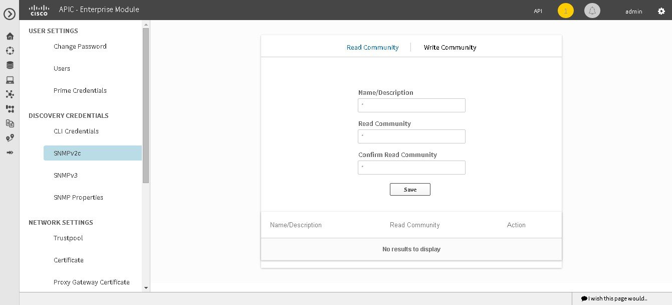
SNMP is an application-layer protocol that provides a message format for communication between SNMP managers and agents. SNMP provides a standardized framework and a common language used for the monitoring and management of devices in a network. The different versions of SNMP are SNMPv1, SNMPv2, SNMPv2c, and SNMPv3.
SNMPv2c is the community string-based administrative framework for SNMPv2. Community string is a type of password, which is transmitted in clear text. SNMPv2c does not provide authentication or encryption (noAuthNoPriv level of security).
Note | In addition to configuring SNMPv2c for device discovery in the controller, a "best effort" Cisco APIC-EM discovery is in place, meaning that devices having SNMP with Read-Only (RO) community string set to "public" will be discovered all the time irrespective of the configured SNMP Read/Write community string. |
You must have successfully deployed the Cisco APIC-EM and it must be operational.
You must have your network's SNMP information available for this configuration procedure.
You must have either administrator (ROLE_ADMIN) or policy administrator (ROLE_POLICY_ADMIN) permissions to perform this procedure.
For information about the user permissions required to perform tasks using the Cisco APIC-EM, see the chapter, "Managing Users and Roles," in the Cisco Application Policy Infrastructure Controller Enterprise Module Configuration Guide.
| Step 1 | In the Home window, click either admin or the Settings icon (gear) at the top right corner of the screen. | ||
| Step 2 | Click the Settings link from the drop-down menu. | ||
| Step 3 | In the Settings navigation pane, click SNMPv2c to view the SNMPv2c window. | ||
| Step 4 | In the
SNMPv2c window, click
Read
Community.
Enter your Read Community values:
| ||
| Step 5 | Click
Save to save your
Read
Community values.
The Read Community values will appear in the table below. | ||
| Step 6 | (Optional) In
the
SNMPv2c window, click
Write
Community.
Enter your Write Community values:
| ||
| Step 7 | (Optional) Click
Save to save your
Write
Community values.
The Write Community values will appear in the table below. |
What to Do Next
If required for your SNMP configuration, proceed to configure either SNMPv3 or SNMP Properties using the GUI.
If you are finished with your SNMP configuration, then proceed to import an X.509 certificate and private key into the controller, if necessary for your network configuration.
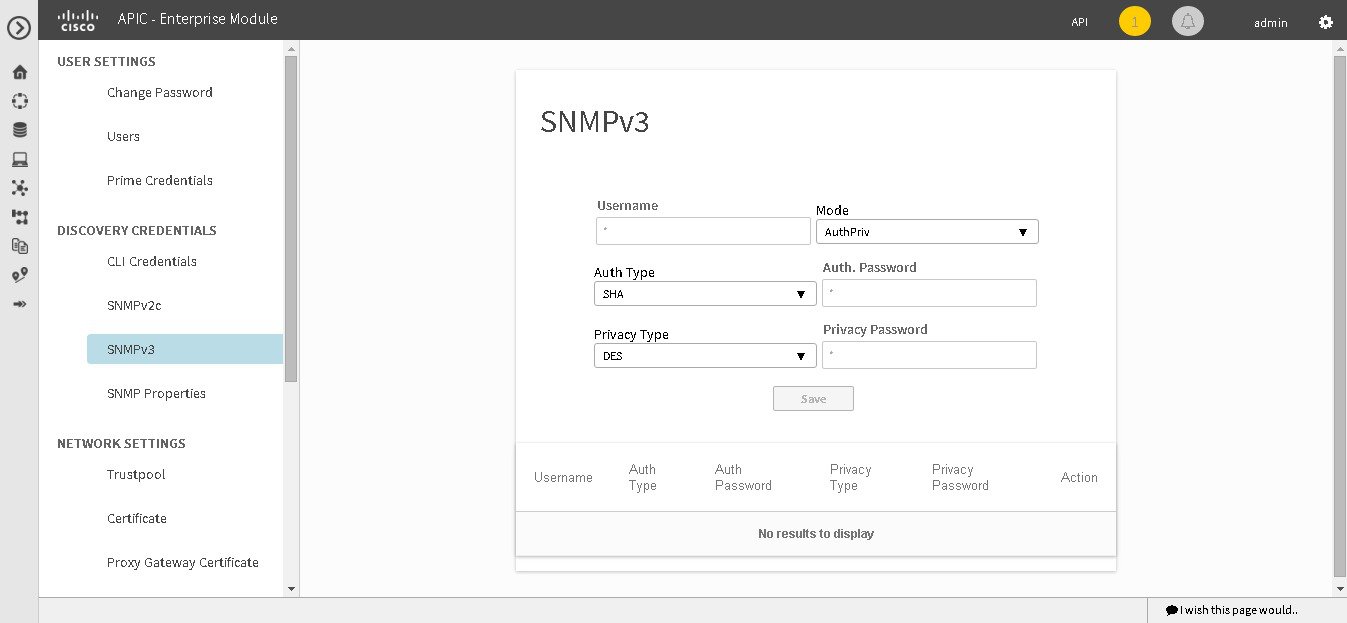
Configuring SNMPv3
You configure SNMPv3 for device discovery in the SNMPv3 window in the Cisco APIC-EM GUI. The SNMP values that you configure for SNMPv3 for the controller must match the SNMPv3 values that have been configured for your network devices. You can configure up to five SNMPv3 settings.
SNMP is an application-layer protocol that provides a message format for communication between SNMP managers and agents. SNMP provides a standardized framework and a common language used for the monitoring and management of devices in a network. The different versions of SNMP are SNMPv1, SNMPv2, SNMPv2c, and SNMPv3.
SNMPv3 provides secure access to devices by a combination of authenticating and encrypting frames over the network. The following are supported SNMPv3 security models:
-
Message integrity—Ensures that a packet has not been tampered with in-transit.
-
Authentication—Determines the message is from a valid source
-
Encryption—Scrambles the packet contents to prevent it from being seen by unauthorized sources
SNMPv3 provides for both security models and security levels. A security model is an authentication strategy that is set up for a user and the role in which the user resides. A security level is the permitted level of security within a security model. A combination of a security model and a security level determines which security mechanism is employed when handling an SNMP packet.
The security level determines if an SNMP message needs to be protected from disclosure and if the message needs to be authenticated. The various security levels that exist within a security model are as follows:
-
noAuthNoPriv—Security level that does not provide authentication or encryption
-
AuthNoPriv—Security level that provides authentication but does not provide encryption
-
AuthPriv—Security level that provides both authentication and encryption
The following table identifies what the combinations of security models and levels mean:
|
Model |
Level |
Authentication |
Encryption |
What Happens |
|---|---|---|---|---|
|
v2c |
noAuthNoPriv |
Community String |
No |
Uses a community string match for authentication. |
|
v3 |
noAuthNoPriv |
User Name |
No |
Uses a username match for authentication. |
|
v3 |
AuthNoPriv |
Either: |
No |
Provides authentication based on the Hash-Based Message Authentication Code (HMAC) Message Digest 5 (MD5) algorithm or the HMAC Secure Hash algorithm (SHA) |
|
v3 |
AuthPriv |
Either: |
Either: |
Provides authentication based on the HMAC-MD5 or HMAC-SHA algorithms. Provides Data Encryption Standard (DES) 56-bit encryption in addition to authentication based on the Cipher Block Chaining (CBC) DES (DES-56) standard or CBC-mode AES for encryption. |
You must have successfully deployed the Cisco APIC-EM and it must be operational.
You must have your network's SNMP information available for this configuration procedure.
You must have either administrator (ROLE_ADMIN) or policy administrator (ROLE_POLICY_ADMIN) permissions to perform this procedure.
For information about the user permissions required to perform tasks using the Cisco APIC-EM, see the chapter, Managing Users and Roles in the Cisco Application Policy Infrastructure Controller Enterprise Module Configuration Guide.
| Step 1 | In the Home window, click either admin or the Settings icon (gear) at the top right corner of the screen. | ||
| Step 2 | Click the Settings link from the drop-down menu. | ||
| Step 3 | In the
Settings navigation pane, click
SNMPv3 to view the
SNMPv3 window.
If you use SNMPv3 in your network to monitor and manage devices, then configure the SNMPv3 values for discovery for your network. | ||
| Step 4 | In the
SNMPv3 window, enter a
Username value and choose a
Mode from the drop down menu.
The following Mode options are available:
| ||
| Step 5 | If you selected
AuthPriv or
AuthNoPriv as a
Mode option, then choose an
Authentication type from the drop down menu and
enter an authentication password.
The following Authentication options are available: | ||
| Step 6 | If you selected
AuthPriv as a
Mode option, then choose a
Privacy type from the drop down menu and enter a
SNMPv3 privacy password.
The SNMPv3 privacy password is used to generate the secret key used for encryption of messages exchanged with devices that support DES or AES128 encryption. The following Privacy type options are available: | ||
| Step 7 | Click
Save to save your SNMPv3 configuration values.
The SNMPv3 configured values will appear in the table below. |
What to Do Next
If required for your SNMP configuration, proceed to configure either SNMPv2c or SNMP Properties using the GUI.
If you are finished with your SNMP configuration, then proceed to import an X.509 certificate and private key into the controller, if necessary for your network configuration.
Configuring SNMP Properties
You configure SNMP properties for device discovery in the SNMP Properties window in the Cisco APIC-EM GUI.

You must have successfully deployed the Cisco APIC-EM and it must be operational.
You must have your network's SNMP information available for this configuration procedure.
You must have either administrator (ROLE_ADMIN) or policy administrator (ROLE_POLICY_ADMIN) permissions to perform this procedure.
For information about the user permissions required to perform tasks using the Cisco APIC-EM, see the chapter, Managing Users and Roles in the Cisco Application Policy Infrastructure Controller Enterprise Module Configuration Guide.
| Step 1 | In the Home window, click either admin or the Settings icon (gear) at the top right corner of the screen. |
| Step 2 | Click the Settings link from the drop-down menu. |
| Step 3 | In the
Settings navigation pane, click
SNMP
Properties to view the
SNMP
Properties window.
Configure the SNMP property settings for discovery in your network. |
| Step 4 | In the
SNMP
Properties window, enter a value in the
Retries field.
The value entered in this field is the number of attempts the controller attempts to use SNMP to communicate with your network devices. |
| Step 5 | In the
SNMP
Properties window, enter a value in the
Timeout field.
The value entered in this field is the length of time in seconds the controller attempts to use SNMP to communicate with your network devices. |
| Step 6 | Click
Apply to save your SNMP configuration values.
You can also click Revert to Defaults to revert to the SNMP property default values. The following are the SNMP property default values: |
What to Do Next
If required for your SNMP configuration, proceed to configure either SNMPv2c or SNMPv3 using the GUI.
If you are finished with your SNMP configuration, then proceed to import an X.509 certificate and private key into the controller, if necessary for your network configuration.
Security
Importing a Certificate
The Cisco APIC-EM supports the import and storing of an X.509 certificate and private key into the controller. After import, the certificate and private key can be used to create a secure and trusted environment between the Cisco APIC-EM, NB API applications, and network devices.
Note | If you have a multi-host deployment and you plan to acquire a valid CA-issued certificate for your controller HTTPS server, then use the virtual IP address that you assigned to the multi-hosts as the Common Name for the certificate when you order. If you are using a host name instead, make sure the host name is DNS-resolvable to the virtual IP address of the multi-host deployment. If you already have a single host Cisco APIC-EM with a previously purchased CA-issued certificate for its external IP address, then it is ideal to use that original physical IP address of the single host as the virtual IP address of the multi-host deployment. This way you can save your investment in the CA-issued certificate and also keep the external client applications, using your Cisco APIC-EM services to continue using the same IP address. |
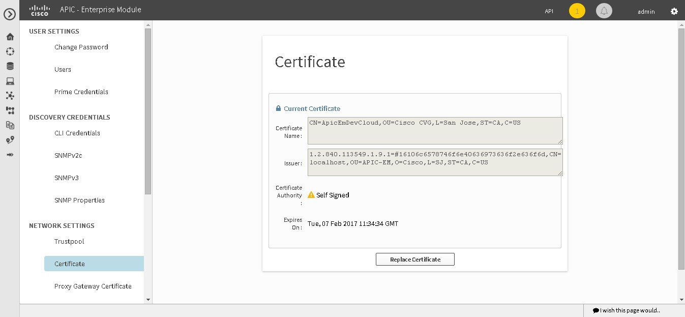
You import a certificate and private key using the Certificate window in the Cisco APIC-EM GUI.
You must have successfully deployed the Cisco APIC-EM and it must be operational.
You must have acquired an X.509 certificate and private key from a well-known certificate authority (CA) for the import.
You must have administrator (ROLE_ADMIN) permissions to perform this procedure.
For information about the user permissions required to perform tasks using the Cisco APIC-EM, see the chapter, Managing Users and Roles in the Cisco Application Policy Infrastructure Controller Enterprise Module Configuration Guide.
| Step 1 | In the Home window, click either admin or the Settings icon (gear) at the top right corner of the screen. | ||||
| Step 2 | Click the Settings link from the drop-down menu. | ||||
| Step 3 | In the Settings navigation pane, click Certificate to view the Certificate window. | ||||
| Step 4 | In the
Certificate window, view the current certificate
data.
When first viewing this window, the current certificate data that is displayed is the controller's self-signed certificate. The self-signed certificate's expiration is set for several years in the future.
Additional displayed fields in the Certificate window include: | ||||
| Step 5 | To replace the
current certificate, click the
Replace
Certificate button.
The following new fields appear: | ||||
| Step 6 | In the
Certificate fields, choose the file format type of
the certificate:
Choose one of the above file types for the certificate that you are importing into the Cisco APIC-EM. | ||||
| Step 7 | If you choose
PEM, then perform the following tasks:
| ||||
| Step 8 | If you choose
PKCS, then perform the following tasks:
| ||||
| Step 9 | Click the Upload/Activate button. | ||||
| Step 10 | Return to the Certificate window to view the updated certificate data. The information displayed in the Certificate window should have changed to reflect the new certificate name, issuer, and certificate authority. |
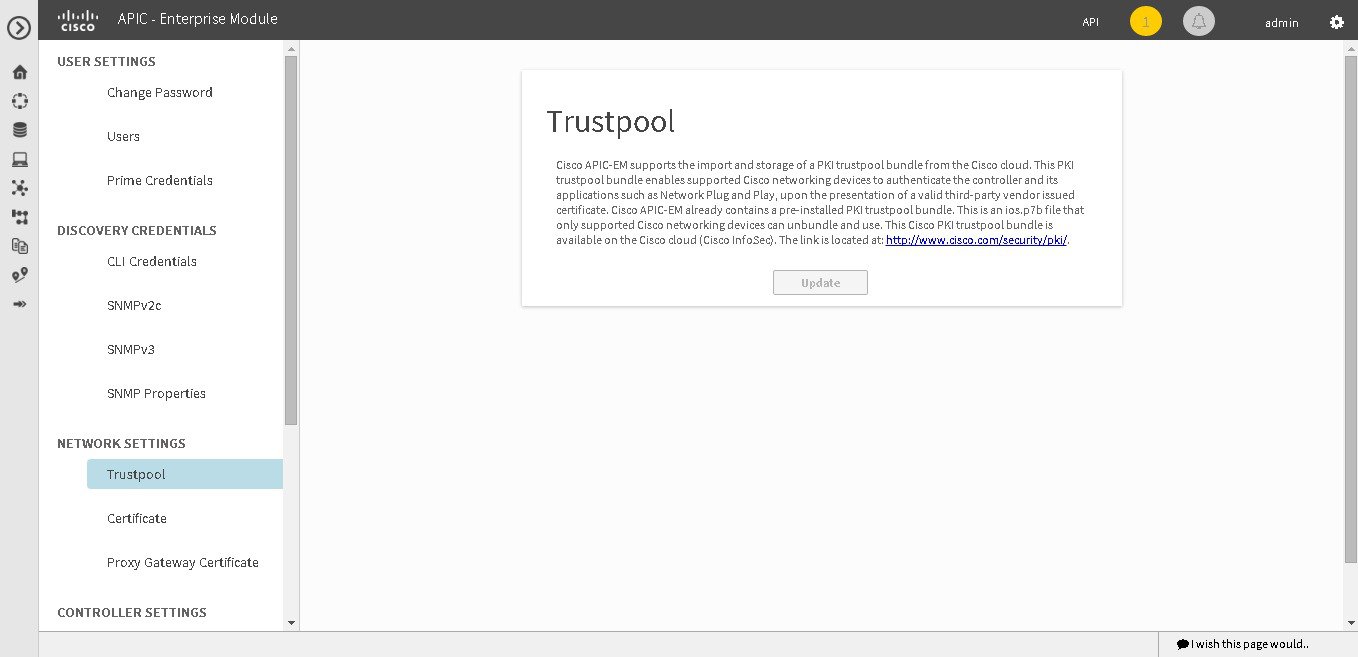
Importing a Trustpool Bundle
The Cisco APIC-EM contains a pre-installed Cisco trustpool bundle (Cisco Trusted External Root Bundle). The Cisco APIC-EM also supports the import and storage of an updated trustpool bundle from Cisco. The trustpool bundle is used by supported Cisco networking devices to authenticate the controller and its applications, such as Network PnP upon the presentation of its CA signed certificate, as well as any other third party that presents a valid CA signed certificate.
Note | The Cisco trustpool bundle is an ios.p7b file that only supported Cisco devices can unbundle and use. This ios.p7b file contains root certificates of valid certificate authorities including Cisco itself. This Cisco trustpool bundle is available on the Cisco cloud (Cisco InfoSec). The link is located at: http://www.cisco.com/security/pki/. |
The trustpool bundle provides you with a safe and convenient way to use the same CA to manage all your network device certificates, as well as your controller certificate. The trustpool bundle is used by the controller to validate its own certificate as well as a proxy gateway certificate (if any), to determine whether it is valid CA signed certificate or not. Additionally, the trustpool bundle is available to be uploaded to the Network PnP enabled devices at the beginning of their PnP workflow so that they can trust the controller for subsequent HTTPS-based connections.
You import the Cisco trust bundle using the Trustpool window in the Cisco APIC-EM GUI.
You must have successfully deployed the Cisco APIC-EM and it must be operational.
You must have administrator (ROLE_ADMIN) permissions to perform this procedure.
For information about the user permissions required to perform tasks using the Cisco APIC-EM, see the chapter, Managing Users and Roles in the Cisco Application Policy Infrastructure Controller Enterprise Module Configuration Guide.
| Step 1 | In the Home window, click either admin or the Settings icon (gear) at the top right corner of the screen. | ||
| Step 2 | Click the Settings link from the drop-down menu. | ||
| Step 3 | In the Settings navigation pane, click Trustpool to view the Trustpool window. | ||
| Step 4 | In the
Trustpool window, click the
Update button.
After clicking this button, the following actions occur:
|
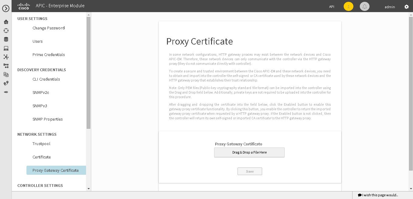
Importing a Proxy Gateway Certificate
In some network configurations, proxy gateways may exist between the Cisco APIC-EM and network devices. Common ports such as 80 and 443 pass through the gateway proxy in the DMZ, and for this reason SSL sessions from the network devices meant for the controller terminate at the proxy gateway. Therefore, these network devices can only communicate with the controller via the proxy gateway. In order for the network devices to establish secure and trusted connections with the controller, or if present, a proxy gateway, then the network devices should have their PKI trust stores appropriately provisioned with the relevant CA root certificates or the server’s own certificate under certain circumstances.
Cisco Network Plug and Play
With the Cisco Network Plug and Play (PnP) application, the Cisco APIC-EM responds to HTTPS requests from supported Cisco network devices and permits these devices to download and install an image and desired configuration. Before a device can download such information from the controller, the initial interaction between the controller and device involves the establishment of a trust relationship.
At first interaction with a PnP enabled device, that PnP enabled device is provisioned by the controller with trust information that includes a CA root certificates bundle or at the least the certificate of the CA that issued the server side certificate. Note that in latter case, the CA may or may not be a well known CA.
In certain Cisco Network Plug and Play scenarios, your network configuration may have a proxy gateway present between the controller and PnP enabled devices. For instance in an IWAN deployment a branch router might communicate to the Cisco APIC-EM through a proxy gateway at the DMZ at initial provisioning. Depending on whether there is a proxy gateway present or not, the trust information provided by the controller at the initial transaction with the devices may correspond to the proxy gateway's or to the controller’s certificate issuer (if the corresponding server certificates are not valid CA signed). On the other hand, in either proxy or non-proxy cases, if the certificate is a simple self-signed certificate, then that certificate will be downloaded by the device into its trust store.
Note | Using a self-signed certificate for either the Cisco APIC-EM or the proxy gateway is strongly discouraged. We strongly recommend using a publicly verifiable CA issued certificate to be installed for the controller, as well as the proxy gateway if one is present. |
With a valid CA issued certificate for the controller or the proxy gateway (if present), the PnP enabled devices can download the trustpool bundle (ios.p7b) containing all the well known CA root certificates. This permits the devices to establish secure connections to the controller or to the proxy gateway for further provisioning and operation of those devices. If such a certificate is not a valid CA issued or self-signed, then the devices will have to download the issuing CA’s or self-signed certificate to proceed further with a secure connection to the controller or a proxy gateway in front of the controller. The Cisco APIC-EM facilitates automatic downloads of the relevant trusted certificates on the devices, depending on the nature of the certificate installed on it. However; when a proxy gateway is present, it provides a provisioning GUI to facilitate similar pre-provisioning.
In network topologies where there is a proxy gateway present between controller and PnP enabled devices, follow the procedure below to import a proxy gateway certificate into the controller.
You have successfully deployed the Cisco APIC-EM and it is operational.
In your network, an HTTP proxy gateway exists between the controller and PnP enabled network devices. The PnP enabled network devices will use the proxy gateway's IP address to reach the Cisco APIC-EM controller and its services.
You have the certificate file currently being used by the proxy gateway. The certificate file contents can consist any of the following:
-
The proxy gateways’s certificate in PEM format, with the certificate being self-signed.
-
The proxy gateway’s certificate in PEM format, with the certificate being issued by a valid, well-known CA, such as the Comodo Group, Symantec, or DigiCert.
-
The proxy gateway’s certificate and the issuing CA root certificate.
Note
The certificate file is structured in the above order as a chain and in PEM format. This is required if the CA is not a valid, well-known CA. For example, a CA not present in the Cisco ios.p7b trust pool bundle.
-
The proxy gateways’s certificate and a Sub CA certificate.
Note
The certificate file is structured in the above order and as a chain in PEM format. This is required if the issuing Root CA, Sub CA is a well-known valid CA such as the Comodo Group, Symantec, or DigiCert.
You must have administrator (ROLE_ADMIN) permissions to perform this procedure.
For information about the user permissions required to perform tasks using the Cisco APIC-EM, see the chapter, Managing Users and Roles in the Cisco Application Policy Infrastructure Controller Enterprise Module Configuration Guide.
The certificate used by the devices and proxy gateway must be imported into the controller by following this procedure.
| Step 1 | In the Home window, click either admin or the Settings icon (gear) at the top right corner of the screen. | ||
| Step 2 | Click the Settings link from the drop-down menu. | ||
| Step 3 | In the Settings navigation pane, click Proxy Gateway Certificate to view the Proxy Certificate window. | ||
| Step 4 | In the
Proxy
Gateway Certificate window, view the current proxy gateway
certificate data (if this exists).
| ||
| Step 5 | To add a proxy
gateway certificate, drag and drop the self-signed or CA certificate to the
Drag n'
Drop a File Here field.
| ||
| Step 6 | Click the
Enable checkbox to enable the proxy gateway
certificate functionality.
By clicking on this checkbox, you enable the controller to return the imported proxy gateway certificate when requested by a proxy gateway. if this checkbox is not checked, then the controller will return its own self-signed or imported CA certificate to the proxy gateway. | ||
| Step 7 | Click the Save button. | ||
| Step 8 | Refresh the Proxy Gateway Certificate window to view the updated proxy gateway certificate data. The information displayed in the Proxy Gateway Certificate window should have changed to reflect the new certificate name, issuer, and certificate authority. |
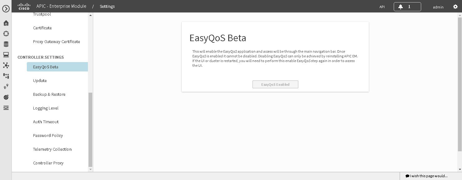
Enabling EasyQoS
You can enable and activate the EasyQoS application on the controller using the EasyQoS Beta window in the Cisco APIC-EM GUI.
You must have successfully deployed the Cisco APIC-EM and it must be operational.
You must have administrator (ROLE_ADMIN) permissions to perform this procedure.
For information about the user permissions required to perform tasks using the Cisco APIC-EM, see the chapter, Managing Users and Roles in the Cisco Application Policy Infrastructure Controller Enterprise Module Configuration Guide
| Step 1 | In the Home window, click either admin or the Settings icon (gear) at the top right corner of the screen. | ||
| Step 2 | Click the Settings link from the drop-down menu. | ||
| Step 3 | In the Settings navigation pane, click EasyQoS Beta to view the EasyQoS Beta window. | ||
| Step 4 | Click the
Enable
EasyQoS button to activate EasyQoS on the controller.
| ||
| Step 5 | Click the
EasyQoS icon in the main Navigation pane to open the
EasyQoS application.
For detailed information about EasyQoS, see the Cisco Application Policy Infrastructure Controller Enterprise Module Configuration Guide. |
What to Do Next
Proceed to apply QoS to your network devices using the EasyQoS application.
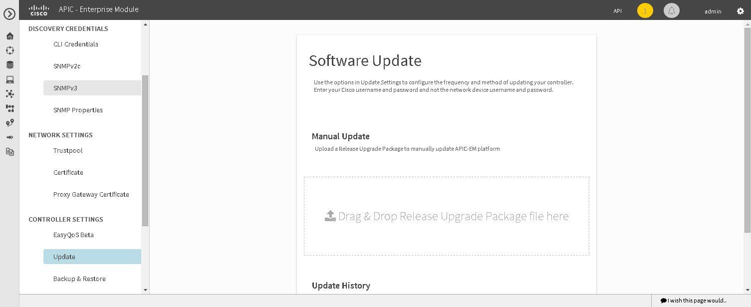
Updating the Cisco APIC-EM Software
You can update the Cisco APIC-EM to the latest version using the controller's software update procedure. This procedure requires that you perform the following tasks:
-
Download the release upgrade pack from the secure Cisco cloud.
-
Run a checksum against the release upgrade pack.
-
Upload the release upgrade pack to the controller using the GUI.
-
Update the controller's software with the release upgrade pack.
Note | In a multi-host cluster, you only need to update a single host. After updating that single host, the other two hosts are automatically updated with the release upgrade pack. |
The release upgrade pack is available for download as a tar file that is also compressed, so the release upgrade pack has a .tar.gz extension. The release upgrade pack itself may consist of any or all of the following update files:
Note | Each release upgrade pack contains an encrypted Cisco signature for security purposes, as well as release version metadata that validates the package. |
You perform the upload and update procedure using the Software Update window in the Cisco APIC-EM GUI.
Note | After a successful upload and software update, you are not permitted to rollback to an earlier Cisco APIC-EM version. |
You must have successfully deployed the Cisco APIC-EM and it must be operational.
You must have administrator (ROLE_ADMIN) permissions to perform this procedure.
For information about the user permissions required to perform tasks using the Cisco APIC-EM, see the chapter, Managing Users and Roles in the Cisco Application Policy Infrastructure Controller Enterprise Module Configuration Guide.
Note | When updating or upgrading the Cisco APIC-EM in a virtual machine within a VMware vSphere environment, you must ensure that the time settings on the ESXi host are also synchronized to the NTP server. Failure to ensure synchronization will cause the upgrade to fail. |
You must have received notification from Cisco that the Cisco APIC-EM software update is available for you to download from the secure Cisco website.
You can be notified about the availability of a Cisco APIC-EM software update in the following ways:
| Step 1 | Review the
information in the Cisco notification about the
Cisco APIC-EM
update file and checksum.
The Cisco notification specifies the location of the release upgrade pack and verification values for either a Message Digest 5 (MD5) or Secure Hash Algorithm (SHA) 512 bits (SHA512) checksum.
| ||||
| Step 2 | Download the release upgrade pack from the secure Cisco website to your laptop or to a location within your network. | ||||
| Step 3 | Run a checksum against the release upgrade pack using your own checksum verification tool or utility (either MD5 or SHA512). | ||||
| Step 4 | Review the
displayed checksum verification value from your checksum verification tool or
utility.
If the output from your checksum verification tool or utility matches the appropriate checksum value in the Cisco notification or from the Cisco secure website, then proceed to the next step. If the output does not match the checksum value, then download the release upgrade pack and perform another checksum. If checksum verification issues persist, contact Cisco support. | ||||
| Step 5 | In the Home window, click either admin or the Settings icon (gear) at the top right corner of the screen. | ||||
| Step 6 | Click the Settings link from the drop-down menu. | ||||
| Step 7 | In the Settings navigation pane, click Software Update to view the Software Update window. | ||||
| Step 8 | If the release
upgrade pack is acceptable to use for updating the controller (checksum value
match in step 4), then drag and drop the release upgrade pack from the download
location on your laptop or in your network onto the
Manual
Update field in the
Software Update window.
After dropping the release upgrade pack onto the Manual Update field, the upload process begins. The upload process may take several minutes depending upon the size of the release upgrade pack and your network connection. During the upload process, you can continue to work with the controller. Once the upload process ends and the update process begins, you will not be able to work with the controller.
| ||||
| Step 9 | Once the
upload process finishes, the update process automatically begins. A message
appears in the GUI stating that the update process has started and is in
progress.
You should refrain from working with the controller during the update process. During the update process, the controller may shut down and restart. The shut down process may last for several minutes.
| ||||
| Step 10 | Once the
update process finishes, you will receive a success or failure notification.
If the update was successful, you will receive a successful update notification and can then proceed working with the controller. If the update was unsuccessful, you will receive an unsuccessful update notification with suggested remedial actions to take.
After the update (or attempted update), information about it will also appear in the Update History field of the Software Update window. The following update data is displayed in this field:
|
Backing Up and Restoring the Cisco APIC-EM
As with any other system upon which your company or organization relies, you need to ensure that the Cisco APIC-EM is backed up regularly, so that it can be restored in case of hardware or other failure.
 Caution | For the IWAN solution application, you must review the Software Configuration Guide for Cisco IWAN on APIC-EM before attempting a back up and restore. There is important and detailed information about how these processes work for the IWAN solution application that includes what is backed up, what is not backed up, recommendations, limitations, and caveats. |
- Information about Backing Up and Restoring the Cisco APIC-EM
- Backing Up the Cisco APIC-EM
- Restoring the Cisco APIC-EM
Information about Backing Up and Restoring the Cisco APIC-EM
The back up and restore procedure for the Cisco APIC-EM can be used for the following purposes:
-
To create a single backup file to support disaster recovery on the controller
-
To create a single backup file on one controller to restore to a different controller (if required for your network configuration)
When you perform a back up using the controller's GUI, you copy and export the controller's database and files as a single file to a specific location on the controller. When you perform a restore, you copy over the existing database and files on the controller using this single backup file.
Note | The Cisco APIC-EM uses PostgreSQL as the preferred database engine for all network data. PostgreSQL is an open source object-relational database system. |
The following files and data are copied and restored when performing a back up and restore:
-
Cisco APIC-EM database
-
Cisco APIC-EM file system and files
-
X.509 certificates and trustpools
-
Usernames and passwords
-
Any user uploaded files (for example, any Network Plug and Play image files)
The database and files are compressed into a single .backup file when performing the back up and restore. The maximum size of the .backup file is 30GB. This number consists of a permitted 20GB maximum size for a file service back up and a 10GB permitted maximum size for the database back up.
Note | The .backup file should not be modified by the user. |
Only a single back up can be performed at a time. Performing multiple back ups at once are not permitted. Additionally, only a full back up is supported. Other types of back ups (for example, incremental back ups) are not supported.
Note | After saving the backup file, you can also download it to another location in your network. You can restore the backup file from its default location in the controller or drag and drop the backup file from its location in your network to restore. |
When performing a backup and restore, we recommend the following:
-
Perform a back up everyday to maintain a current version of your database and files.
-
Perform a back up and restore after making any changes to your configuration. For example, when changing or creating a new policy on a device.
-
Only perform a back up and restore during a low impact or maintenance time period.
When a back up is being performed, you will be unable to delete any files that have been uploaded to the file service and any changes you make to any files may not be captured by the back up process. When a restore is being performed, the controller is unavailable.
Note | You cannot schedule nor automate a back up and restore at this time. Additionally, once started you cannot manually cancel either the back up or restore process. |
Multi-Host Cluster Back Up and Restore
In a multi-host cluster, the database and files are replicated and shared across three hosts. When backing up and restoring in a multi-host cluster, you need to first back up on one of the three hosts in the cluster. You can then use that backup file to restore all three hosts in the cluster. However, you need not perform the restore operation on each of the hosts. You simply restore one of the hosts in the cluster. The controller replicates the restored data to the other hosts automatically.
Note | The back up and restore process in a multi-host cluster requires that the Cisco APIC-EM software and version must be the same for all three hosts. |
Backing Up the Cisco APIC-EM
You can back up your controller using the Backup & Restore window.

You must have successfully deployed the Cisco APIC-EM and it must be operational.
You must have administrator (ROLE_ADMIN) permissions to perform this procedure.
For information about the user permissions required to perform tasks using the Cisco APIC-EM, see the chapter, Managing Users and Roles in the Cisco Application Policy Infrastructure Controller Enterprise Module Configuration Guide.
| Step 1 | In the Home window, click either admin or the Settings icon (gear) at the top right corner of the screen. | ||||
| Step 2 | Click the Settings link from the drop-down menu. | ||||
| Step 3 | In the Settings navigation pane, click Backup & Restore to view the Backup & Restore window. | ||||
| Step 4 | In the
Backup
& Restore window, create a backup file by clicking on the
Create
New Backup button.
After clicking the Create New Backup button, a Backup in Progress window appears in the GUI. During this process, the Cisco APIC-EM creates a compressed .backup file of the controller database and files. This backup file is also given a time and date stamp that is reflected in its file name. The following file naming convention is used: yyyy-mm-dd-hh-min-seconds (year-month-day-hour-seconds). For example: backup_2015_08_14-08-35-10
This backup file is then saved to a default location within the controller. You will receive a Backup Done! notification, once the back up process is finished. Only a single backup file at a time is stored within the controller.
| ||||
| Step 5 | (Optional)
Create a copy of the backup file to another location.
After a successful back up, a Download link appears in the GUI. Click the link to download and save a copy of the backup file to a location on your laptop or network. |
What to Do Next
When necessary and at an appropriate time, proceed to restore the backup file to the Cisco APIC-EM.
Restoring the Cisco APIC-EM
You can restore your controller using the Backup & Restore window.
The following restore options are available:
-
You can restore from the last know backup file on the controller.
-
You can also restore from an archived backup file that was saved and moved to another location on your network.
Caution | The Cisco APIC-EM restore process restores the controller's database and files. The restore process does not restore your network state and any changes made by the controller since the last backup, including any new network policies that have been created, any new or updated passwords, or any new or updated certificates/trustpool bundles. |
Note | You can only restore a backup from a controller that is the same software version as the controller where the backup was originally taken from. |
You must have successfully deployed the Cisco APIC-EM and it must be operational.
You must have administrator (ROLE_ADMIN) permissions to perform this procedure.
For information about the user permissions required to perform tasks using the Cisco APIC-EM, see the chapter, Managing Users and Roles in the Cisco Application Policy Infrastructure Controller Enterprise Module Configuration Guide.
You must have successfully performed a back up of the Cisco APIC-EM database and files following the steps in the previous procedure.
| Step 1 | In the Home window, click either admin or the Settings icon (gear) at the top right corner of the screen. | ||||
| Step 2 | Click the Settings link from the drop-down menu. | ||||
| Step 3 | In the Settings navigation pane, click Backup & Restore to view the Backup & Restore window. | ||||
| Step 4 | To restore the
backup file, click on the
Restore
from last Backup button.
You can also drag and drop the backup file from its location in your network onto the Drag and Drop a backup file field in this window. During a restore, the backup file copies over the current database.
| ||||
| Step 5 | After the
restore process completes, log back into the controller's GUI.
If the restore process was successful, you will be logged out of the controller and its GUI. You will need to log back in.
To check whether the restore process was successful, you can either review the Backup History field of the Backup & Restore window or access the Grapevine root and to run the grape backup display command.
| ||||
| Step 6 | (Optional) Using
a Secure Shell (SSH) client, log into the host (physical or virtual) with the
IP address that you specified using the configuration wizard.
| ||||
| Step 7 | (Optional) When prompted, enter your Linux username ('grapevine') and password for SSH access. | ||||
| Step 8 | (Optional) Enter
the
grape
backup display command at the prompt to confirm that the restore
process was completed and successful.
$ grape backup display Check the command output to ensure that the restore process was completed and successful. Look for the property operation marked "restore" in the command output, with the latest start_time and ensure that the status is marked as a "success". | ||||
| Step 9 | (Optional) Using the Secure Shell (SSH) client, log out of the appliance. | ||||
| Step 10 | Return to the
controller's GUI and review the
Backup
History field of the
Backup
& Restore window.
After the restore, information about it appears in the Backup History field of the Backup & Restore window. The following update data is displayed in this field:
|
Service Logs
Changing the Logging Level for Services
You can change the logging level for the Cisco APIC-EM services by using the Changing the Logging Level window in the Cisco APIC-EM GUI.
A logging level determines the amount of data that is captured to the log files. Each logging level is cumulative, that is, each level contains all the data generated by the specified level and any higher levels. For example, setting the logging level to Info also captures Warn and Error logs.
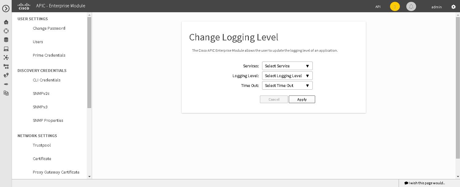
The default logging level for services in the controller is informational (Info). You can change the logging level with the GUI to set it to debug or trace to capture more information.
Caution | Any logs collected at the Debug level or higher should be handled with restricted access. |
Note | The log files are created and stored in a centralized location on your controller. From this location, the controller can query and display them in the GUI The total compressed size of the log files is 2GB. If log files created are in excess of 2GB, then the pre-existing log files are overwritten with the newer log files. |
You must have successfully deployed the Cisco APIC-EM and it must be operational.
You must have administrator (ROLE_ADMIN) permissions to perform this procedure.
For information about the user permissions required to perform tasks using the Cisco APIC-EM, see the chapter, Managing Users and Roles in the Cisco Application Policy Infrastructure Controller Enterprise Module Configuration Guide.
| Step 1 | In the Home window, click either admin or the Settings icon (gear) at the top right corner of the screen. | ||
| Step 2 | Click the Settings link from the drop-down menu. | ||
| Step 3 | In the
Settings navigation pane, click
Changing
the Logging Level to view the
Changing
Logging Level window.
The Logging Level table appears with the following fields: | ||
| Step 4 | In the
Changing
Logging Level
window, choose a service from the
Services field to adjust its logging level.
| ||
| Step 5 | In the
Changing
Logging Level
window, choose the new logging level for the service from
the
Logging
Level field.
The following logging levels are supported on the controller: | ||
| Step 6 |
In the
Changing
Logging Level
window, choose the time period for the logging level from
the
Timeout field for the logging level adjustment.
You configure logging level time periods in increments of 15 minutes up to an unlimited time period. | ||
| Step 7 | Review your
selection and click the
Apply button.
To cancel your selection click the Cancel button. The logging level for the specified service is set. |
Searching the Service Logs
You can search various controller service logs using the Search Logs window in the Cisco APIC-EM GUI.
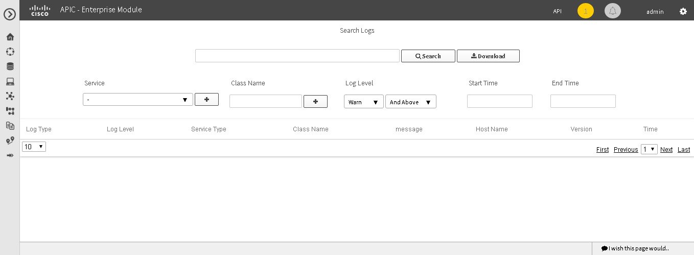
The following log files are reviewed during a search:
You must have successfully deployed the Cisco APIC-EM and it must be operational.
You must have either administrator (ROLE_ADMIN) or policy administrator (ROLE_POLICY_ADMIN) permissions to perform this procedure.
For information about the user permissions required to perform tasks using the Cisco APIC-EM, see the chapter, "Managing Users and Roles," in the Cisco Application Policy Infrastructure Controller Enterprise Module Configuration Guide.
| Step 1 | In the Home window, click either admin or the Settings icon (gear) at the top right corner of the screen. | ||
| Step 2 | Click the
Logs link from the drop-down menu.
The
Search
Logs window appears. In the
Search
Logs window, you can search the controller service logs by
performing the following tasks:
| ||
| Step 3 | (Optional) Enter
a string value in the
Search
Logs field at the top of the
Search
Log window and click the
Search button.
The log search results are displayed at the bottom of the Search Logs window in a table. You can view the following information from the search:
Below the table are numerical filters. Adjust these filters to limit the number of logs displayed in the table (10, 25, 50, 100) or to view groups of a logs at a time (First, Previous, Next, Last, or 1-3). | ||
| Step 4 | (Optional) In
the
Search
Logs window, choose a service from the
Services drop-down menu for the search and click the
plus sign (+).
You can add several different services to your search, by choosing from the drop-down menu and then clicking the plus sign(+).
| ||
| Step 5 | (Optional) In
the
Search
Log window, type in a Java class in the
Class
Name field and click the plus sign (+).
You can add several different Java classes to your search, by choosing from the drop-down menu and then clicking the plus sign(+). | ||
| Step 6 | (Optional) In
the
Search
Logs
window, choose a logging level from the
Log
Level drop-down menu.
The following logging levels are supported: | ||
| Step 7 | (Optional)
Adjust the logging level by choosing an appropriate condition in the second
Log
Level drop-down menu.
The following logging level adjustments are supported:
| ||
| Step 8 | (Optional) In
the
Search
Logs window, enter a start time for the logs in the
Start
Time field for the search or use the calendar icon.
If entering a date and time directly, use the following formats: | ||
| Step 9 | (Optional) In
the
Search
Logs window, enter an end time for the logs in the
End
Time field for the search or use the calendar icon.
If entering a date and time directly, use the following formats: | ||
| Step 10 | Review your
log search settings and then click the
Search button.
The log search results are displayed at the bottom of the Search Log window in a table. Below the table are numerical filters. Adjust these filters to limit the number of logs displayed in the table (10, 25, 50, 100) or to view groups of a logs at a time (First, Previous, Next, Last, or 1-3). |
What to Do Next
Proceed with any additional service log searches.
Downloading the Service Logs
You can download various controller service logs using the Search Logs window in the Cisco APIC-EM GUI.
The following log files are reviewed during a search and download:
You must have successfully deployed the Cisco APIC-EM and it must be operational.
You must have either administrator (ROLE_ADMIN) or policy administrator (ROLE_POLICY_ADMIN) permissions to perform this procedure.
For information about the user permissions required to perform tasks using the Cisco APIC-EM, see the chapter, "Managing Users and Roles," in the Cisco Application Policy Infrastructure Controller Enterprise Module Configuration Guide.
| Step 1 | In the Home window, click either admin or the Settings icon (gear) at the top right corner of the screen. | ||
| Step 2 | Click the
Logs link from the drop-down menu.
The Search Logs window appears. In the Search Logs window, you can download the controller service logs by performing the following tasks: | ||
| Step 3 | (Optional) Enter
a string value in the
Search
Logs field at the top of the
Search
Logs window and click the
Download button.
The log download results are displayed at the bottom of the Search Logs window. | ||
| Step 4 | (Optional) In
the
Search
Log window, choose a service from the
Services drop-down menu for the download and click
the plus sign (+).
You can add several different services to your download, by choosing from the drop-down menu and then clicking the plus sign(+).
| ||
| Step 5 | (Optional) In
the
Search
Log window, choose a Java class from the
Class drop-down menu for the download and click the
plus sign (+).
You can add several different Java classes to your download, by choosing from the drop-down menu and then clicking the plus sign(+). | ||
| Step 6 | (Optional) In
the
Search
Logs
window, choose a logging level from the
Log
Level drop-down menu.
The following logging levels are supported: | ||
| Step 7 | (Optional)
Adjust the logging level by choosing an appropriate condition in the second
Log
Level drop-down menu.
The following logging level adjustments are supported:
| ||
| Step 8 | (Optional) In
the
Search
Logs window, enter a start time for the logs in the
Start
Time field for the download or use the calendar icon.
If entering a date and time directly, use the following formats: | ||
| Step 9 | (Optional) In
the
Search
Logs window, enter an end time for the logs in the
End
Time field for the download or use the calendar icon.
If entering a date and time directly, use the following formats: | ||
| Step 10 | Review your log search settings and then click the Download button. The log download results are displayed at the bottom right of the Search Log window as a page icon displaying the number of logs using the following format: Search Results (5).log. | ||
| Step 11 | Click on the
icon for the log download results.
A new window opens that displays the log download data. This data is organized using the following parameters: |
What to Do Next
Proceed with any additional service log downloads.
Configuring the Authentication Timeout
You can configure authentication timeouts that require the user to log back into the controller with their credentials (username and password) using the Authentication Timeout window in the Cisco APIC-EM GUI.
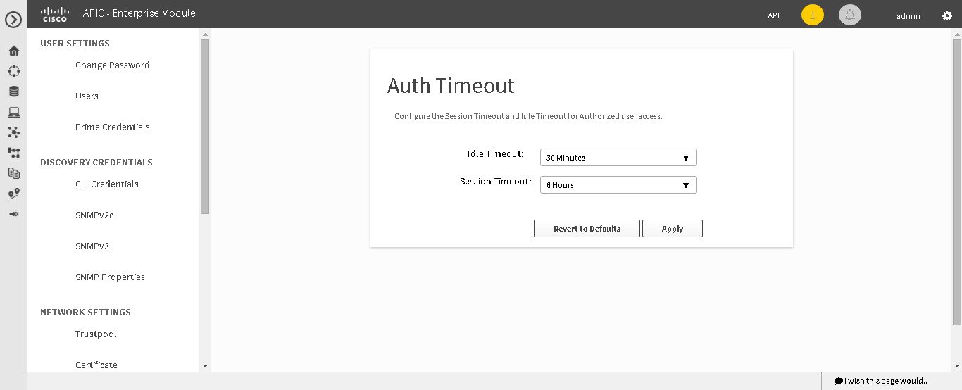
The following authentication timeout values can be configured:
-
Idle timeout—Time interval that you can configure before the controller requires re-authentication (logging back in with appropriate credentials) due to Cisco APIC-EM inactivity. Idle timeouts are API-based, meaning that idle timeout is the time the controller is idle between API usages and not GUI mouse clicks or drags.
-
Session timeout—Time interval that you can configure before the controller requires re-authentication (logging back in with appropriate credentials). This is a forced re-authentication.
Note | Approximately 2-3 minutes before your session is about to idle timeout, a pop-up warning appears in the GUI stating that your session is about to idle timeout and asking if you wish to continue with the current session. Click Cancel to ignore the warning and idle timeout of the session within approximately 2-3 minutes. Click OK to continue the session for another 30 minutes. |
You must have successfully deployed the Cisco APIC-EM and it must be operational.
You must have administrator (ROLE_ADMIN) permissions to perform this procedure.
For information about the user permissions required to perform tasks using the Cisco APIC-EM, see the chapter, Managing Users and Roles in the Cisco Application Policy Infrastructure Controller Enterprise Module Configuration Guide
| Step 1 | In the Home window, click either admin or the Settings icon (gear) at the top right corner of the screen. |
| Step 2 | Click the Settings link from the drop-down menu. |
| Step 3 | In the Settings navigation pane, click Authentication Timeout to view the Authentication Timeout window. |
| Step 4 | (Optional)
Configure the idle timeout value using the
Idle
Timeout drop-down menu.
You can configure the idle timeout value in increments of 5 minutes, up to an hour. The default value is 30 minutes. |
| Step 5 | (Optional)
Configure the session timeout value using the
Session
Timeout drop-down menu.
You can configure the session timeout value in increments of 30 minutes, up to 24 hours. The default value is six hours. |
| Step 6 | Click the
Apply button to apply your configuration to the
controller.
To restore the authentication timeout defaults to the controller, click the Revert to Defaults button. |
Configuring Password Policies
As an administrator, you can control the number of consecutive, invalid user login attempts to the Cisco APIC-EM. Once a user crosses the threshold set by you as administrator, the user's account is locked and access is refused. Additionally, as an administrator, you can also configure the length of time that the user account is locked. The user account will remain locked until the configured time period expires.
You configure these controller access parameters for the Cisco APIC-EM using the Password Policy window.
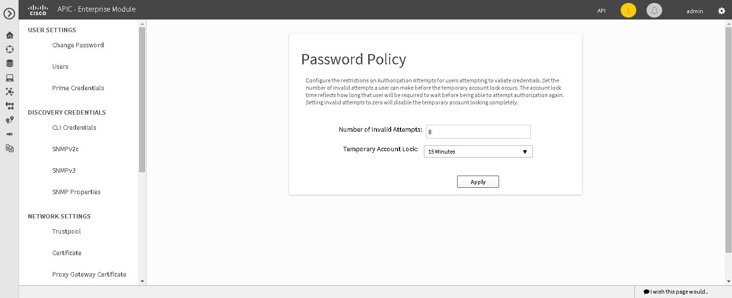
The following password policy functionality is supported:
-
As an administrator, you can set the number of consecutive, invalid user login attempts to the controller. These consecutive, invalid user login attempts can be set from 0 to 10 attempts, with 8 attempts being the default value. Setting invalid attempts to 0 will disable the feature of locking a user with invalid password attempts.
-
As an administrator, you can set the length of time a user account is locked. Permitted lock time intervals for a user account range from 1-3600 seconds, with 900 seconds being the default value.
-
When a user account is locked due to the number of consecutive, invalid login attempts, entering correct credentials will still result in a login failure until the expiration of the configured lock out time period.
-
An administrator can unlock the user account at any time.
We recommend that you create at least two administrator accounts for your deployment. With two administrator accounts, if one account is locked for whatever reason then the other account can be used to unlock that locked account.
Note
For information about how to unlock a user account, see the Chapter 4, Managing Users and Roles in the Cisco Application Policy Infrastructure Controller Enterprise Module Configuration Guide.
-
A locked user account is unlocked when the configured lock out time period expires.
-
A user account can never be permanently locked, but to deny access permanently, an administrator can delete the account.
You must have successfully deployed the Cisco APIC-EM and it must be operational.
You must have administrator (ROLE_ADMIN) permissions to perform this procedure.
For information about the user permissions required to perform tasks using the Cisco APIC-EM, see the chapter, Managing Users and Roles in the Cisco Application Policy Infrastructure Controller Enterprise Module Configuration Guide.
| Step 1 | In the Home window, click either admin or the Settings icon (gear) at the top right corner of the screen. |
| Step 2 | Click the Settings link from the drop-down menu. |
| Step 3 | In the Settings navigation pane, click Password Policy to view the Password Policy window. |
| Step 4 | (Optional) Configure the number of permitted consecutive, invalid password attempts by choosing from the Number of Invalid Attempts drop-down menu. |
| Step 5 | (Optional) Configure the time interval for locking a user account by choosing from the Temporary Account Lock drop-down menu. |
| Step 6 | Click the Apply button to apply your configuration to the controller. |
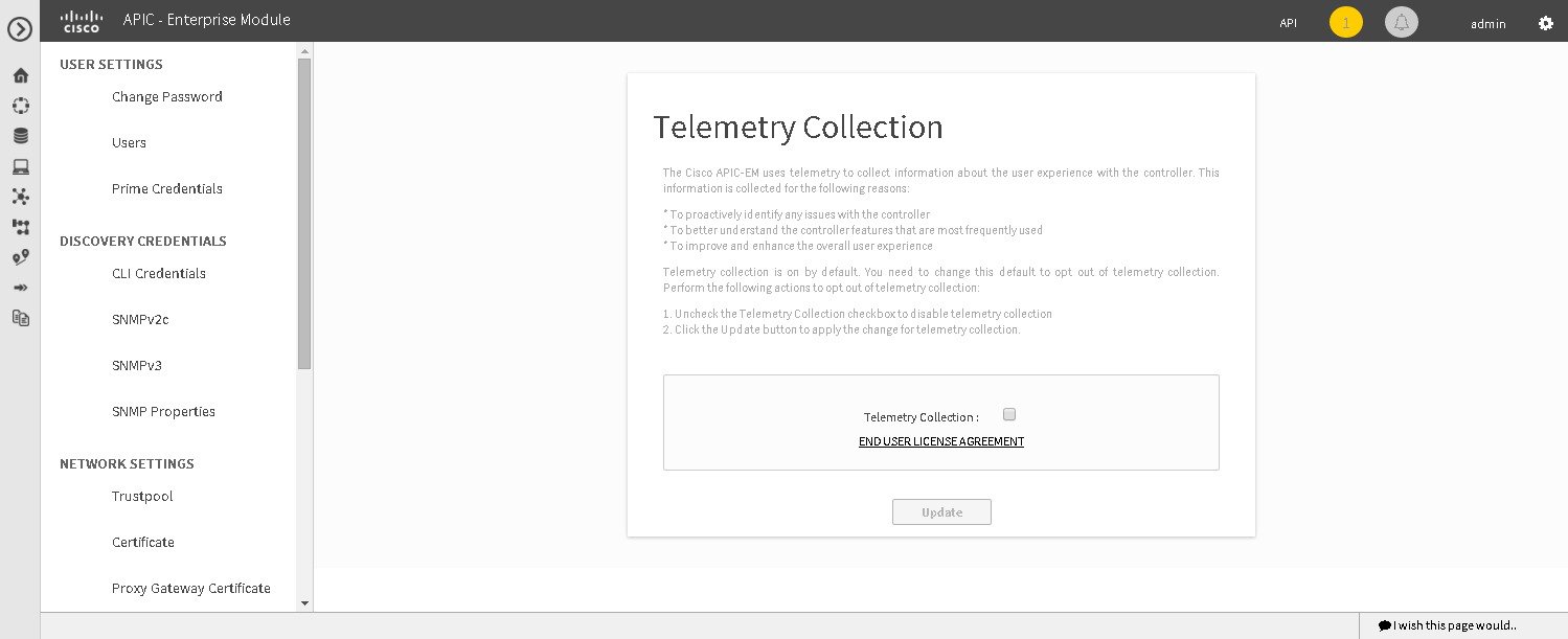
Telemetry Collection
The Cisco APIC-EM uses telemetry to collect information about the user experience with the controller. This information is collected for the following reasons:
-
To proactively identify any issues with the controller
-
To better understand the controller features that are most frequently used
-
To improve and enhance the overall user experience
You are able to view the some of the collected telemetry data using the following methods:
-
View the logs using the Cisco APIC-EM GUI—For information about this method, see Searching the Services Logs in Chapter 5, Configuring the Cisco APIC-EM Settings.
-
View the logs using the Grapevine console— For information about this method, see Troubleshooting Services in Chapter 6, Troubleshooting the Cisco APIC-EM.
Telemetry is enabled with a telemetry service that collects data from the many other controller services. The telemetry service supports Data Access Service (DAS). The telemetry service uploads data to the Cisco Clean Access Agent (CAA) infrastructure on the Cisco cloud using HTTPS.
Telemetry collection is on by default. If you wish to opt out of telemetry collection, then perform the steps in the following procedure.
You must have successfully deployed the Cisco APIC-EM and it must be operational.
You must have administrator (ROLE_ADMIN) permissions to perform this procedure.
For information about the user permissions required to perform tasks using the Cisco APIC-EM, see the chapter, Managing Users and Roles in the Cisco Application Policy Infrastructure Controller Enterprise Module Configuration Guide.
| Step 1 | In the Home window, click either admin or the Settings icon (gear) at the top right corner of the screen. |
| Step 2 | Click the Settings link from the drop-down menu. |
| Step 3 | In the
Settings navigation pane, click
Telemetry Collection to view the
Telemetry
Collection window.
When accessing the Telemetry Collection window for the first time, the GUI displays a blue box with a check that indicates that telemetry collection is enabled. |
| Step 4 | (Optional) Click the End User License Agreement to review the agreement for telemetry collection. |
| Step 5 | (Optional) Uncheck the Telemetry Collection blue box to disable telemetry collection. |
| Step 6 | (Optional) Click the Update button to apply the change for telemetry collection. |
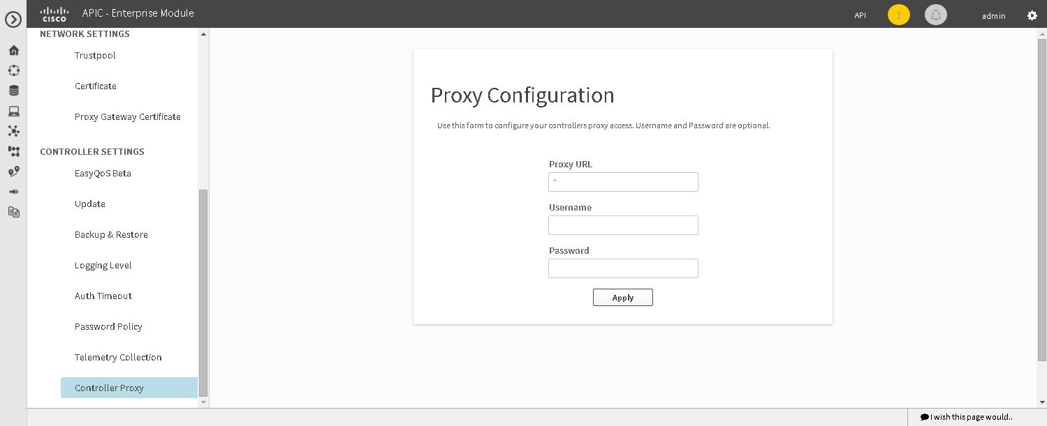
Configuring the Proxy
If the Cisco APIC-EM is unable to communicate directly with the telemetry server in the Cisco cloud, then a message will appear in the controller GUI (for an admin user) requesting that you configure access to the proxy. This message will contain a direct link to the Proxy Configuration window where you can configure this access. To configure access, enter the appropriate settings for the proxy server that exists between the controller and the telemetry server.
You configure these settings using the Proxy Configuration window in the Cisco APIC-EM GUI.
You must have successfully deployed the Cisco APIC-EM and it must be operational.
You must have administrator (ROLE_ADMIN) permissions to perform this procedure.
For information about the user permissions required to perform tasks using the Cisco APIC-EM, see the chapter, Managing Users and Roles in the Cisco Application Policy Infrastructure Controller Enterprise Module Configuration Guide.
| Step 1 | In the Home window, click either admin or the Settings icon (gear) at the top right corner of the screen. |
| Step 2 | Click the Settings link from the drop-down menu. |
| Step 3 | In the Settings navigation pane, click Controller Proxy to view the Proxy Configuration window. |
| Step 4 | Enter the proxy server's URL address. |
| Step 5 | (Optional) If the proxy server requires authentication, then enter the username for access to the proxy server. |
| Step 6 | (Optional) If the proxy server requires authentication, then enter the password that is required for access to the proxy server. |
| Step 7 | Click the Apply button to apply your proxy configuration settings to the controller. |
 Feedback