Validated Profile: Healthcare (Nonfabric) Vertical
Available Languages
Bias-Free Language
The documentation set for this product strives to use bias-free language. For the purposes of this documentation set, bias-free is defined as language that does not imply discrimination based on age, disability, gender, racial identity, ethnic identity, sexual orientation, socioeconomic status, and intersectionality. Exceptions may be present in the documentation due to language that is hardcoded in the user interfaces of the product software, language used based on RFP documentation, or language that is used by a referenced third-party product. Learn more about how Cisco is using Inclusive Language.
- US/Canada 800-553-2447
- Worldwide Support Phone Numbers
- All Tools
 Feedback
 Feedback
Document Purpose and Usage
The purpose of this document is to outline the typical healthcare deployment profile that Cisco Systems recommends. It provides guidelines for a typical nonfabric deployment that uses Catalyst Center and also serves as a validation document you can refer to during the process. This document's theoretical sections should be used in conjunction with its practical sections to help a deployment engineer understand the service requirements. The document will also help the deployment engineer make the best decisions for their particular network during deployment and configuration.
Target Audience
The target audience for this healthcare profile is the technical staff that is responsible for engineering and operating the network, as well as the implementation teams.
Solution Overview
Healthcare network environments require a specialized set of demands that includes security, enhanced network services, efficient network management, seamless mobility, network high availability, and location services. The following topics describe the key considerations for a large, evolving healthcare network that needs to meet today's requirements.
Security
The healthcare system needs to protect the personal medical records and financial information of its patients. In the United States, hospitals and medical centers are required to have Health Insurance Portability and Accountability Act (HIPAA)-compliant wired and wireless networks that can provide complete and constant visibility into their network traffic. For these healthcare organizations, it is paramount to have security resilience to maintain their business continuity. In today’s complex IT environment, it has become a necessity to ensure that only trusted users are granted access to a network, to protect the integrity of the business amidst ever-evolving threats. Cisco Identity Service Engine (ISE) allows organizations to segment networks connecting trusted users and endpoints with trusted resources. Cisco ISE provides organizations the flexibility to deploy secure network access control to authorized users and network endpoints.
The rapid rise in encrypted traffic is changing the threat landscape. As more businesses become digital, a significant number of services and applications are using encryption as the primary method of securing information. Encryption technology has enabled much greater privacy and security for enterprises and individuals that use the internet to communicate and transact business. Traditional flow monitoring, as implemented in the Cisco Network as a Sensor (NaaS) solution and using NetFlow, provides a high-level view of network communications by reporting the addresses, ports, and byte and packet counts of a flow.
Catalyst Center's Rogue Management application detects and classifies threats, enabling network administrators, network operators, and security operators to monitor network threats. Catalyst Center helps to quickly identify the highest-priority threats, allowing you to monitor these threats in the Rogue Management dashboard found in Cisco Catalyst Assurance.
The Cisco Adaptive Wireless Intrusion Prevention System (aWIPS) is a wireless intrusion threat detection and mitigation mechanism that uses an advanced approach to detect threats and manage performance. When an AP detects a threat, Cisco aWIPS jumps into action. It combines network traffic analysis, network device and topology information, signature-based techniques, and anomaly detection to deliver highly accurate and complete wireless threat prevention.
Mobility
In today's healthcare environment, caregivers, patients, and equipment are constantly moving. Cisco wireless mobility solutions help healthcare services become more efficient. Caregivers can access information and order services from wherever they happen to be, using notebook computers, tablet PCs, wireless IP phones, and new dual-mode phones (which can connect over either the hospital’s Wi-Fi network or cellular networks). Physicians on rounds can use their wireless laptops to update patient charts and provide dictation. These updates are immediately available to other staff members, helping to ensure that decisions are made based using the latest patient information. Dieticians, nurses, and therapists can check orders, keep track of special needs, and review test results using wireless tablets. Patients no longer need to wait in line to be registered. Instead, a roaming registration clerk can bring a wireless tablet to the patient in the lobby or emergency room. Patients who need immediate treatment can even be registered bedside after receiving critical care.
Network Management
Catalyst Center revolutionizes how you design, build, and manage your networks with faster, flexible deployment and simpler, centralized network management. This allows your systems to be up and running in days rather than months. Catalyst Center's infrastructure and solutions also provide a digital-ready foundation that facilitates greater patient engagement and smarter operations. Organizations could reap the following benefits:
● Use automation to lower complexity and costs: Roll out and update clinical, research, and factory networks faster and reduce day-to-day operational and network management costs with automation, management, and assurance.
● Faster innovation with actionable insights: Generate network-wide analytics to provide more relevant care and research experiences, increase clinician and staff productivity, and optimize space usage.
● Reduce risks with security everywhere: Keep critical patient data secure with continuous and faster threat detection and protection, with security embedded network wide.
High Availability
This document covers the network foundation and architectures that enable advanced clinical applications and biomedical devices to operate in a protected, interactive, resilient, and responsive environment, which is based on the best practices of a robust healthcare environment.
Single points of failure are eliminated, and rapid convergence architectures and technologies are used throughout the network. Advanced technologies are used to maximize uptime for mission-critical applications, such as Electronic Health Records (EHRs), Picture Archiving and Communications Systems (PACS), and biomedical devices. Ether Channel and/or SVL switching fabric can be replaced or upgraded without any interruption of service. Interior Gateway Protocol (IGP) helps ensure the highest level of resiliency during times of network convergence. Continuous uptime features include In-Service Software Upgrade (ISSU), Rolling AP upgrade (N+1), and Stateful Switch Over (SSO). These features reduce network downtime by allowing software upgrades to be performed while routers, switches, and wireless controllers are active.
Location Services
Intelligence on the location of mobile resources streamlines business and clinical processes and frees staff to deliver high-quality care. Now, leading healthcare organizations are adopting location solutions to improve their awareness of critical resources, including equipment and people. The Cisco Location-Aware Healthcare solution can help healthcare organizations monitor and optimize workflows and increase responsiveness, productivity, and efficiency. Location-aware health services have converged on three main solution areas: asset management, workflow optimization, and patient tracking. Most location-based solutions in the market today require proprietary, vendor-specific hardware and software. This limits the variety of use cases they can serve and creates management complexity. By contrast, Cisco Spaces is an open platform that sits at the nexus of a broad ecosystem of device and software partners, channel partners, and industry associations.
Location services provide the following benefits:
● Locate a Wi-Fi device by identifying the AP that's nearest to that device. This method provides less granular location accuracy than triangulation. However, it can be deployed in venues with fewer APs or can extend Wi-Fi location analytics to outdoor APs.
● Locate connected and unconnected Wi-Fi devices, interferers, and active RFID tags using Cisco CleanAir technology and non-Wi-Fi interferers.
● Determine the precise location of connected Wi-Fi devices within 1 to 3 meters (depending on your deployment) using advanced angle-of-arrival (AoA) technology combined with FastLocate.
● Use hyperlocation to find connected Wi-Fi devices via the RSSI triangulation of probing signals, as well as network data packets, for faster refresh and greater location detail.
● Use analytics to generate insights into the Wi-Fi devices used by visitors at a venue, based on their location and movement patterns.
Traffic Optimization
Quality of Service (QoS) is a key component of traffic transmission efficiency in congested environments. QoS allows applications to be marked to reflect their importance for business operations. In a wired environment, these markings can be used to set different priority levels, as well as allocate bandwidth and control. In a wireless environment, these marking are also used to associate applications with one of eight user priority queues. Association with a queue is also used to differentiate the statistical frequency an application accesses the wireless medium. Proper marking at the infrastructure level results in optimized downstream traffic, where applications of higher business relevance can receive a statistical transmission advantage, and real-time applications can be prioritized over non-interactive applications. The same effect is applicable upstream when the client station marks QoS properly.
Guest Anchoring
An increasingly common medical application is guest access, which delivers internet access to individuals who are not directly under the control of the healthcare system’s IT policy. To maintain the organization’s needs, guest traffic should take lower precedence than medical applications. In addition to the classic guest user class, medical facilities also require a physician guest user class. These physicians need access beyond a simple internet connection and typically require access to resources within the facility’s private network. Because these physicians are not necessarily employees, they are likely to use a variety of uncontrolled client devices.
Additional security considerations are necessary to prevent the spread of viruses and the possibility of opening doors into the private network. Catalyst Center offers the guest anchoring solution for wireless guest users. The guest capability uses a secure tunnel from the controller within the network to a guest controller in the unsecured network area (a DMZ) to direct guest traffic outside of the enterprise network.
Wi-Fi Coexistence
WPA3 is the third and latest iteration of the Wi-Fi Protected Access standard developed by the Wi-Fi Alliance. WPA3 replaces the previous standard, WPA2. The WPA3 Enterprise form extends the solid foundation provided by WPA2 Enterprise by making it mandatory to use Protected Management Frames (PMF) on all connections. This security feature protects against dangerous attacks like denial of service (DoS), honeypots, and eavesdropping. With the number of internet-connected devices forecasted to reach billions in the coming years, there is an implicit need for better security, and WPA3 is the answer. WPA2 devices have been present for many years in Wi-Fi networks, so it is critical to have a mode of deployment where both WPA2 and WPA3 devices can coexist. This coexistence helps Wi-Fi networks migrate gradually from WPA2 to WPA3-based networks. The Wi-Fi Alliance introduced the WPA3 transition modes for personal and enterprise networks. To benefit security, WPA3 transition modes migrate all client devices to WPA3 only as they join the transition mode WLAN. However, if the network is composed of multiple physical locations where some locations are set to WPA2 and other locations are set to WPA3/WPA2 transition mode, the migrated clients will fail when moved to a location with WPA2 only.
Security Compliance
Mobile Device Management (MDM) VPN posture refers to the security compliance state of a mobile device, typically managed by an organization’s MDM solution, when it connects to a network via a VPN. Ensuring correct VPN posture involves evaluating the health and compliance of the device to determine whether it meets security policies before granting network access. Key elements of MDM paired with VPN include compliance checks on OS, antivirus/malware protection, device encryption, and password policy. MDM solutions can integrate with VPNs to enforce posture checks before allowing access to corporate resources. For example, Cisco AnyConnect or other enterprise VPNs can work alongside MDM to evaluate the device’s health. Based on the device posture, MDM systems can grant or deny VPN access. If a device doesn’t comply with security policies (for example, the device is missing a patch), access to the VPN is restricted until the device is remediated.
Healthcare Profile Summary
The following table highlights the key focus areas of the healthcare solution profile.
| Key Deployment Area |
Feature |
| Security |
● Group-based Policy (also known as TrustSec software-defined segmentation)
● Encrypted Traffic Analytics (ETA)
● Peer-to-peer blocking
● Rogue management and aWIPS
|
| Mobility |
● 802.11r fast roaming
● Intra-wireless controller and inter-wireless controller roaming
|
| Network Management |
Catalyst Center |
| High Availability |
● AP SSO
● N+1 SSO
|
| Location Services |
● Cisco Spaces
● CMX
|
| Traffic Optimization |
● FastLane
● MQOS
|
| Guest Anchoring |
● Wireless guest (Central Web-auth)
● Wired guest
|
Hardware and Software Specifications
The solution is validated with the hardware and software listed in the following table.
| Role |
Model Name |
Hardware Platform |
Software Version |
|
| Catalyst Center Controller |
DN2-HW-APL-XL |
Catalyst Center Appliance 3-Node Cluster |
Cisco DNA Center 2.3.5.6 |
Catalyst Center 2.3.7.6 |
| Identity Management, RADIUS Server |
ISE-VM-K9 |
Cisco Identity Services Engine Virtual Appliance |
Cisco Identity Services Engine 2.7 Patch 6, |
Cisco Identity Services Engine 3.3 Patch 3 |
| Stealthwatch |
SMCVE/FCVE |
Stealthwatch Management Console/Stealthwatch Flow Collector |
7.3.2 |
7.3.2 |
| Cisco SD-WAN |
vManage |
Cisco vManage |
20.6.3.1 |
20.6.3.1 |
| ASR1001-X ASR1002-HX |
Cisco ASR Series Aggregation Services Routers |
17.6.5a, 17.9.5a |
17.9.5a, 17.12.3a |
|
| ISR-4351 ISR-4431 |
Cisco ISR Integrated Services Router |
17.6.5a, 17.9.5a |
17.9.5a, 17.12.3a |
|
| 8300 |
Cisco Edge Services Router |
17.6.5a, 17.9.5a |
17.9.5a, 17.12.3a |
|
| Cisco Collapsed Core Node |
C9500-48Y4C C9600 |
Cisco Catalyst 9500 Series Switches Cisco Catalyst 9600 Series Switches Cisco Catalyst 6800 Series Switches |
17.6.6a, 17.9.4a, 17.9.5 |
17.9.5, 17.12.4 |
| Cisco Access Node |
C9300-48P C9300-24P C9407R C9200-48P 3850-48U |
Cisco Catalyst 9300/3850 Series Switches |
17.9.4a, 17.9.5, 16.12.10a |
17.9.5, 17.12.4, 16.12.10a |
| Cisco Wireless Controller |
C9800-40-K9 C9800-L-K9 |
Cisco Catalyst 9800 Series Wireless Controller |
17.9.4a, 17.9.5, 17.12.3 |
17.9.5, 17.12.3 |
| Cisco IOT Node |
IE-5000 |
Cisco Catalyst IE5000 Rugged Series |
15.2(8)E1 |
15.2(8)E1 |
| Cisco Access Points |
9120-AXI 9130-AXI 2800 3700 3800 |
Cisco Catalyst/Cisco Aeronet Access Points |
17.9.4a, 17.9.5, 17.12.3 |
17.9.5, 17.12.3 |
| Wireless Phones |
Cisco Wireless IP Phone 8821, Apple iPhone 12, Xiaomi 11i |
— |
— |
— |
| Wired Phones |
Cisco Wired Phone |
— |
— |
— |
| Wireless Laptops |
Apple macOS (M1 Chip), Windows 10 |
— |
— |
— |
| Wired Laptops |
Windows 10 |
— |
— |
— |
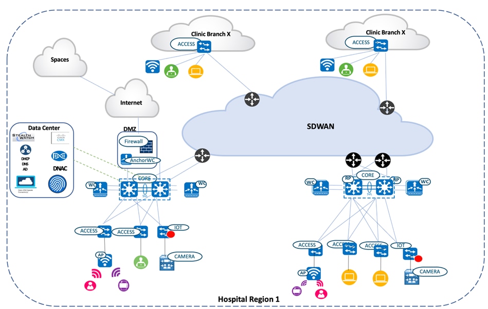
Solution Topology
Solution Use Cases
| Category |
Function |
Use Case |
| Security |
Intent-based networking |
Catalyst Center – Cisco ISE Integration. |
| Site creation (under Network Hierarchy). |
||
| Device discovery using the discovery tool and PnP. |
||
| Template Programmer. |
||
| Group-based policy microsegmentation |
Communication between a nursing station and a doctor. |
|
| Accessing critical patient records. |
||
| Intersite source group tag (SGT) propagation using inline tagging. |
||
| P2P blocking with IPSK |
Legacy devices that support wpa_supplicant. |
|
| Rogue and aWIPS |
Threat detection and mitigation on a WLAN. |
|
| Encrypted traffic analytics |
Threat detection on TLS communications between a wired workstation and the Emergency Health Records (EHR). |
|
| AI endpoint analytics |
Ad-hoc device plugged into the hospital network. |
|
| Mobility |
Wireless roaming |
Physicians and nurses visiting patients and updating patient records. |
| Traffic optimization |
AutoQoS |
Priority queuing for Apple clients using Fastlane. |
| MQoS |
CVD-queuing profile using Catalyst Center application policy. |
|
| Guest anchoring |
Wireless guest access |
Foreign guest on a campus site and anchor guest controllers on a DMZ servicing the guest clients. |
| Wired guest access |
Wired medical endpoints that need internet access for maintenance, a software update, or a firmware update. |
|
| Location services |
Detect and locate in Cisco Spaces |
Hospital staff tracking the location of medical devices (like fusion pumps or a health monitoring device) using Wi-Fi asset tags. |
| High availability |
AP/client SSO |
Network services for caregivers that are always available during unforeseen network outages or a planned maintenance window, aided by redundant and resilient networks both within a site and across sites. |
| N+1 SSO |
||
| ISSU/rolling AP upgrades |
||
| Coexistence |
802.11ax/Dual gRPC |
Backward compatibility of 802.11ax provides a cohesive environment for the coexistence of legacy and next-gen wireless clients. Dual gRPC for Intelligent Capture (iCAP) and Cisco Spaces plays a key role in optimizing the flow of telemetry data and operational commands between Cisco infrastructure, particularly in high-performance wireless environments. |
| Compliance |
MDM, VPN, Posture |
Healthcare organizations must comply with regulations like HIPAA, which mandate strict controls over the access, storage, and transmission of personal health information. MDM VPN posture ensures that any device accessing the network via VPN complies with these regulatory requirements (such as encryption, patching, and antivirus software). |
Scale
Solution test verified the scale numbers listed in the following table. To view the scale numbers for the Catalyst Center appliance, see the Cisco DNA Center Data Sheet.
| Category |
Value |
| Device inventory |
4000 |
| Number of devices per site |
100 |
| Multiple Catalyst Center appliances |
2 |
| Number of buildings and floors |
1000 |
| Number of wireless controllers per site |
2 |
| Number of APs in inventory |
6000 |
| Number of endpoints |
75,000 (50,000 wired, 25,000 wireless) |
| Number of SSIDs |
5 |
| Number of SGACLs |
100 |
| Number of SGTs |
50 |
| Assurance scale (number of syslog messages and traps per second) |
Customized by event type |
Solution Keynotes
Security
In a healthcare environment, data security is essential for ensuring patient privacy and assuring availability. The system must be available to transport data at the performance levels required by caregivers to treat their patients effectively. High availability requires strict security measures to ensure that both accidental and intentional system misuse does not degrade system performance below acceptable service levels.
Intent-Based Networking Using Catalyst Center
An Administrator can design a network hierarchy that reflects multiple sites spread across multiple geographies. This hierarchy provides a consolidated view of the area, buildings, and floors which house nodes comprising of switches, routers, wireless controllers, IOT nodes, and APs. These nodes are discovered by Catalyst Center using the Discovery tool (which leverages automation). The administrator can then assign these nodes to the corresponding sites without needing to be physically present at any of these sites. APs are added to the Catalyst Center inventory via the PnP workflow, which intelligently assigns them to the corresponding wireless controllers.
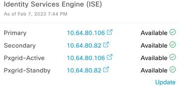
Cisco Identity Services Engine (ISE) is integrated with Catalyst Center through a PxGrid association. This association inherently gets to know the Cisco ISE clustered environment with Active/Standby pxGrid and PAN personas. The following figure illustrates the Cisco ISE persona information displayed by Catalyst Center on the System 360 page.
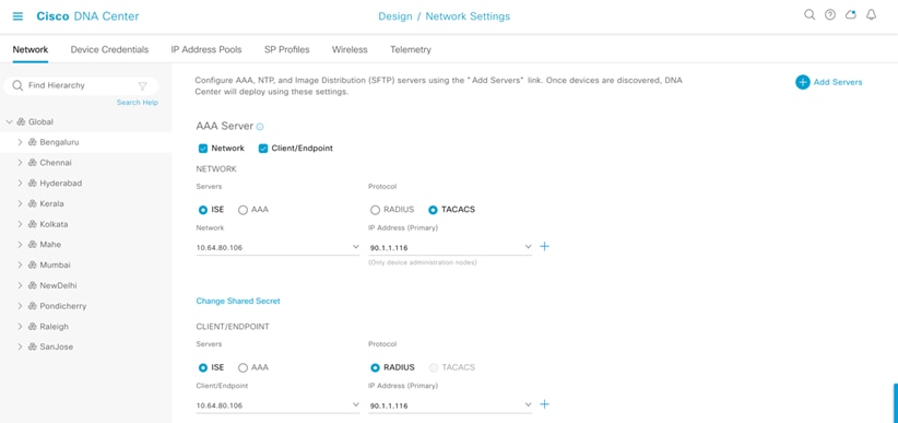
In Catalyst Center's Network Settings page, you can map multiple Policy Service Nodes (PSN) to the appropriate sites in order to efficiently manage and load balance the policy service requests propagating across different locations.
The network devices assigned to the site in this example create a Network Access Device entry for the equivalent devices in Cisco ISE.
The intent to be consumed has been designed in Catalyst Center until the previous step. The device provisioning workflow takes care of converting the intent into CLIs. The AAA/RADIUS configurations would then be provisioned on the corresponding network node, which completely binds the node in the RADIUS and Group-based Policy boundary for the Access, Distribution, and Core/Router device roles. Wireless controllers are brought into the Group-based Policy boundary with the help of Template Programmer.
Group-Based Policy Microsegmentation
Administrators can segment users, guests, and IoT/medical devices into the appropriate logical network to limit the movement of threats around a network. Administrators enjoy the following benefits:
● Granular control over who connects to the network.
● Integration with RADIUS servers for dynamic VLAN assignment, security policies, and so on.
● Support for various authentication types, such as EAP-TLS, PEAP, and EAP-MSCHAPv2.
Administrators can also control access to the network nodes (routers, switches, and wireless controllers) by using security protocol like TACACS+ and RADIUS to achieve centralized authentication, authorization, and accounting (AAA) services to manage users and devices.
In this section, we'll describe an end-to-end use case that covers communication between hospital staff, who access critical patient records with CTS enforcement points being the wireless and wired segments. A basic knowledge of group-based policies is a prerequisite for understanding this use case.
Communication Between Nursing Station and Doctor
The healthcare network has both wired and wireless employees. In this example, we'll illustrate a phone call between a nurse on a wired phone in the nursing station and the doctor on a wireless phone. The wired phone connected to the access switch is MAB-authenticated, and the corresponding CTS tags for the phone are installed on the switch. The access switch propagates the CTS tags to the uplink SVL core networking node through the CTS manual configured on the directly connected links between the access switch and the core networking device. The wireless controllers, connected in split pair fashion to the SVL core, also has a CTS manually configured between them on the directly connected links. The wireless controllers have the SGACL policies downloaded for the corresponding destination group tag (DGT), which is assigned to the doctor's wireless phone (which is attached to the local mode AP that's backhauling all of the traffic to the wireless controller servicing the clients in the central switching pattern). The most likely SGACL policy for any traffic directed to the doctor’s wireless phone is shown as follows.
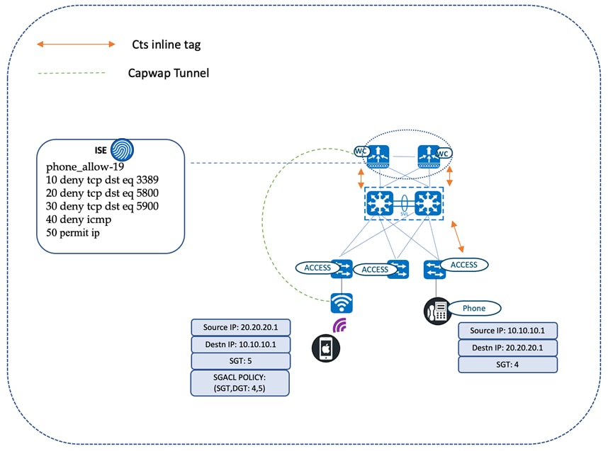
9840-ha#show cts role-based permissions from 4 to 5
IPv4 Role-based permissions from group 4:NurseStation to group 5:Doctors:
Phone_allow-19
RBACL Monitor All for Dynamic Policies: FALSE RBACL Monitor All for Configured Policies: FALSE
Role-based IP access list phone_allow-19 (downloaded)
10 deny tcp dst eq 3389
20 deny tcp dst eq 5800
30 deny tcp dst eq 5900
40 deny icmp
50 permit ip
Accessing Critical Patient Records
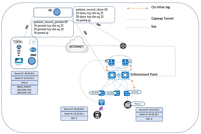
Critical patient records stored in data centers should be accessed by authorized personnel only. The core networking device at every site is the gateway for traffic entering and exiting from the enterprise domain. These core devices, which are in the critical data path, need to be aware of the group-based policy bindings to enforce the traffic that exits the network. The devices learn the policy bindings of the remote network through an SXP session with the Cisco ISE node. This applies to traffic originating from both wireless and wired users requesting access to patient records stored in the data center. The source CTS tag is propagated to the switch as part of the certificate-based authentication (EAP-TLS) and carried inline until it reaches the core node. The core device then inspects the received SGTs and searches the static policy for a match for the policy pair (SGT and DGT). In this example, the DGT is the CTS tag for the patient records. Based on the authorization level of the requesting entity, access to patient records is either granted or denied at the core device. The traffic does not need to propagate until the record-maintaining servers to deny access to unauthorized users. In the following diagram, the nurse station cannot access critical patient records, whereas the doctors can.
cts sxp enable
cts sxp default password 7 14141B180F0B293F37
cts sxp connection peer 90.1.1.117 source 192.169.50.31 password default mode local both
HCA-C3-CORE-9600-1#show cts sxp connections SXP : Enabled
Highest Version Supported: 4 Default Password : Set Default Key-Chain: Not Set
Default Key-Chain Name: Not Applicable Default Source IP: Not Set
Connection retry open period: 120 secs Reconcile period: 120 secs
Retry open timer is not running
Peer-Sequence traverse limit for export: Not Set Peer-Sequence traverse limit for import: Not Set
Peer IP : 90.1.1.117
Source IP : 192.169.50.31
Conn status : On (Speaker) :: On (Listener) Conn version : 4
Conn capability : IPv4-IPv6-Subnet Speaker Conn hold time : 120 seconds Listener Conn hold time : 120 seconds Local mode : Both
Connection inst# : 1
TCP conn fd : 1(Speaker) 2(Listener) TCP conn password: default SXP password Keepalive timer is running
Duration since last state change: 49:17:02:47 (dd:hr:mm:sec) :: 49:17:02:47 (dd:hr:mm:sec)
Total num of SXP Connections = 1
9600-SVL#show cts role-based permissions from 4 to 6
IPv4 Role-based permissions from group 4:NurseStation to group 6:record_room: patient_record_deny-20
9600-SVL#show cts role-based permissions from 5 to 6
IPv4 Role-based permissions from group 5:Doctors to group 6:record_room: patient_record_permit-20
Remote Branch Clinic Accessing Critical Patient Records
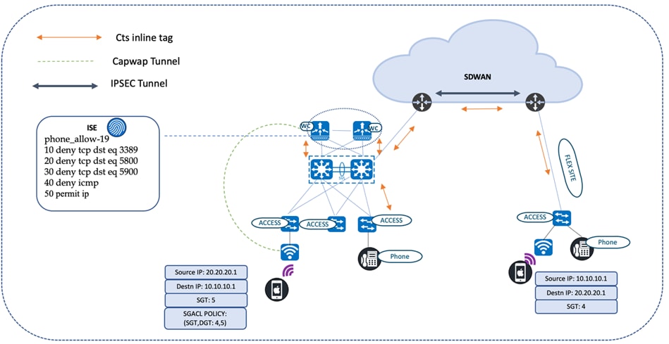
The patient records are accessed from small branch clinics (also known as flex sites). The wireless controller at the main campus provides service to the flex APs in the branch clinics. The source CTS tags are carried inline until they reach the access node at the branch site. The access device inspects the received SGTs and searches the policy table to confirm if there is a match for the policy pair (the SGT and DGT). In this example, the DGT is the CTS tag for patient records.
The security standards in a healthcare environment comply to HIPAA regulatory requirements. The security use cases are dynamic, which requires a mechanism to service the day-n change requests of security policies. Change of authorization (CoA) covers many of these dynamic changes and helps maintain compliance, manage access, and enhance overall security. If the branch clinic has an emergency request to certain medical records, the SGACL policies in Cisco ISE can be modified to allow permission to access the resource by granting permit on the ACLs between the SGT and DGT. The SGACL change is pushed to the network devices as part of the CoA transaction, allowing the devices to download the updated policies for the corresponding policy pair (SGT and DGT).
Intersite SGT Propagation Using Inline Tagging
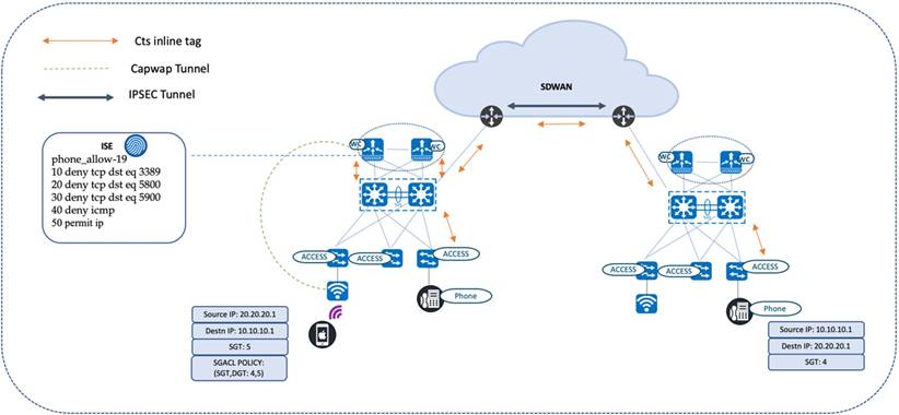
The CTS tags for end users at hospitals located across different geographies are propagated using a CTS inline tag. CTS tags are carried across the site encapsulated in the IPSEC header.

The following diagram illustrates a phone call between a nurse station and a doctor, who are located in different sites. Inline tagging is enabled on all egress interfaces, from the access switch (to which the nurse station phones are connected) to the wireless controller (to which the doctor’s wireless phone is connected). Inline tagging is also enabled on the egress interfaces of the intermediate nodes, such as the core device and SD-WAN edges. The IPSEC-enabled SD-WAN edges use the overlay to transport the CTS tags.
Peer-to-Peer Blocking with IPSK
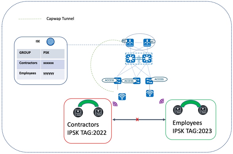
Not all endpoints in a wireless network support the 802.1x supplicant for secure attachment. The endpoints that don't can use WPA-PSK instead. Since all users in the same WLAN using PSK share the same preshared key, it exposes the key to possible misuse, resulting in unauthorized access. To overcome this security gap, IPSK allows you to assign a unique preshared key to a particular user or user group. IPSK security can be further enhanced with peer-to-peer blocking when there is a requirement to disallow users with the same PSK (or users in the same or different WLANs) from interacting with each other.
The following diagram illustrates users connected to the same WLAN with the allow-private-group option enabled in the WLAN profile. In this scenario, the users which were authorized by the same authorization profile on Cisco ISE are able to communicate with each other (since they share the same IPSK tag). Users with different IPSK tags were authorized using unique Cisco ISE authorization profiles. As a result, these users will not be able to communicate with each other. For a description of how to enable peer-to-peer blocking, see "Create a Model Config Design for Advanced SSID" in the Cisco Catalyst Center User Guide.
9840-ha#show wireless client summary ipsktag Number of Clients: 5
MAC Address AP Name State Ipsk Tag
009a.d2f0.591a AP687D.B402.D02C Run b0a8b704cbc54008
6887.c6f0.6176 AP687D.B402.D02C Run 7166848ee93a1c8f
98af.65a6.d966 AP7079.B333.8CD2 Run ea52373d6bfc33f0
b2aa.e402.9228 AP687D.B402.D02C Run b0a8b704cbc54008
d037.45a7.f5f1 AP84F1.4782.1858 Run b0a8b704cbc54008
Rogue Management
Catalyst Center has a rogue management application that detects and classifies WLAN threats and enables the network administrator/operator to monitor them. Rogue APs are used to hack sensitive information in the WLAN. Consider a hacker transmitting a series of Clear to Send (CTS) frames, which mimic an AP instructing one client to transmit while instructing other clients to wait, which results in a disruption of service to the legitimate clients. A user could also plug in a rogue AP in the WLAN and build an ad-hoc network to intercept network traffic and hijack client sessions. Catalyst Center constantly monitors all nearby APs and automatically discovers and collects information about rogue APs. When Catalyst Center receives a rogue event from a managed AP, it responds in the following ways:
● If the unknown AP is not managed by Catalyst Center, Catalyst Center applies the rogue classification rules.
● If the unknown AP is not using the same SSID as your network, Catalyst Center verifies whether the AP is connected to the corporate wired network and extends to the wired network. If the rogue AP is physically connected to the corporate network's switch port , Catalyst Center classifies the AP as Rogue on wire. Cisco switches managed by Catalyst Center are required for the Rogue on wire feature to work.
● If the AP is unknown to Catalyst Center and is using the same SSID as your network, Catalyst Center classifies the AP as Honeypot.
● If the unknown AP is not using the same SSID as your network and is not connected to the corporate network, Catalyst Center verifies whether it is causing any interference. If it is, Catalyst Center classifies the AP as an Interferer and marks the rogue state as Potential Threat. The threshold level for classifying interferers on the network is greater than -75 dBm.
● If the unknown AP is not using the same SSID as your network, and is not connected to the corporate network, Catalyst Center verifies whether it is a neighbor. If it is, Catalyst Center classifies the AP as Neighbor and marks the rogue state as Informational. The threshold level for classifying the rogue AP as a neighbor AP is less than or equal to -75 dBm.
Adaptive Wireless Intrusion Prevention System
The Cisco Adaptive Wireless Intrusion Prevention System (aWIPS) is a wireless intrusion threat detection and mitigation app. With this fully infrastructure-integrated solution, you can continually monitor wireless traffic on both wired and wireless networks. Instead of waiting until damage or exposure has occurred, you can use this network intelligence to pinpoint attacks and proactively prevent new attacks. For more information on the Rogue Management and aWIPS apps, see the Cisco Catalyst Center Rogue Management and aWIPS Application Quick Start Guide.
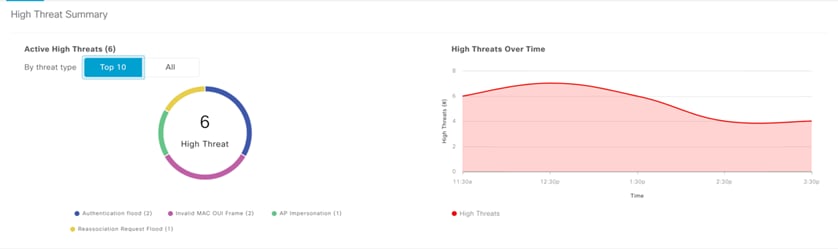
Catalyst Center supports the following standard signatures, which detect the various denial of service (DoS) attacks:
● Authentication flood
● Association flood
● CTS flood
● RTS flood
● Broadcast probe
● Disassociation flood
● Disassociation broadcast
● Deauthentication flood
● Deauthentication broadcast
● EAPOL logoff flood
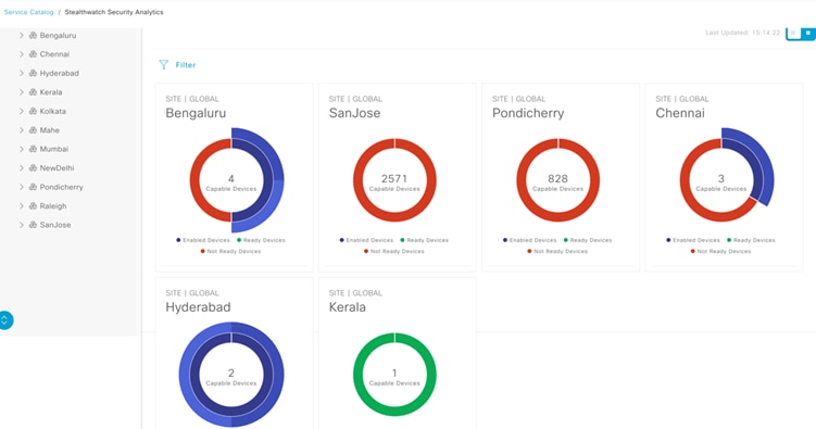
Encrypted Traffic Analytics
Catalyst Center's Stealthwatch Security Analytics (SSA) application can be used during the provisioning of Catalyst access switches to exercise ETA/NaaS use cases. Healthcare organizations must ensure that the most secure TLS libraries and cipher suites are used for communications between wired workstations throughout a medical facility and EHR systems, regardless of where the workstations and EHR systems are deployed. As access to EHR services in the cloud becomes more common (and in some cases, required), these communications need to be analyzed more closely for any signs of suspicious activity.
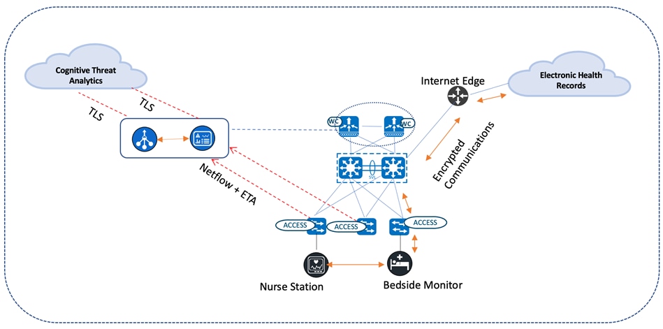
The intraflow metadata, or information about the events that occur inside of a flow, can be collected, stored, and analyzed within a flow monitoring framework. This data is especially valuable when traffic is encrypted because deep-packet inspection is no longer viable. This intraflow metadata, called Encrypted Traffic Analytics (ETA), is derived by using new data elements or telemetry that is independent of protocol details, such as the lengths and arrival times of packets within a flow. These data elements apply equally well to both encrypted and unencrypted flows. ETA extracts two main data elements: the initial data packet (IDP) and the sequence of packet length and time (SPLT). These elements are then communicated using a dedicated NetFlow template to Cisco Stealthwatch Enterprise.
When used in conjunction with Flexible NetFlow, a complete view of the flow's life is available, allowing you to identify malicious traffic as well as anomalous behavior and customizable policy violations in your network. When implementing ETA, in addition to cryptographic assessment, the metadata collected can be used to detect malware within the encrypted traffic without the need to decrypt the traffic when Cisco Stealthwatch is integrated with Cognitive Intelligence. When Flexible NetFlow and DNS information is combined with the ETA metadata found in the IDP, other ETA data elements (such as the sequence of packet length and times (SPLT)) provide a valuable way to identify malware through the detection of suspicious traffic. By default, only traffic (including DNS queries) that crosses the enterprise network perimeter outside of the enterprise address space (i.e. internet-bound traffic) is sent to the Cognitive Intelligence cloud for malware analysis. All traffic is monitored, and records are exported to the Cisco Stealthwatch flow collector. After processing, the flow collector sends only the metadata for this external traffic to the Cognitive Intelligence cloud in an encrypted TLS tunnel for further analysis. All other internal traffic is processed by the flow collector for conformance with the policies established in Cisco Stealthwatch, as well as for the cryptographic assessment based on ETA data. The following diagram depicts communication between a local medical server, a bedside monitor, and a nurse's workstation, as well as communications between these devices and a cloud-based EHR system. For more information about enabling SSA on access switches, see the Stealthwatch Security Analytics Service on Catalyst Center User Guide.
AI Endpoint Analytics
The Cisco AI Endpoint Analytics application provides next-generation endpoint visibility by pairing AI-driven analytics with network-driven deep-packet inspection. The majority of endpoints in the healthcare segment are Internet of Things (IoT)-based. This positions security as a major challenge for network administrators as they monitor these endpoints. Consider the case of a doctor plugged in to a patient’s health monitoring device, which is connected to the hospital's network. What if this device spread malware throughout the network, resulting in widespread issues? Cisco AI Endpoint Analytics comes to the rescue by minimizing the damage.
The first step in securing the endpoints is to identity the type of the devices, which is also known as endpoint profiling. Endpoint Analytics does its best to identify the maximum number of unknown endpoints in the enterprise network based on Deep Packet Inspection (DPI) and Machine Learning (ML). Endpoint profiling starts with aggregating and analyzing endpoint data from various data sources. Examples of these data sources include network devices or appliances supporting deep packet inspection and Cisco Identity Services Engine (ISE). Cisco AI Endpoint Analytics provides granular endpoint profiling details by defining the endpoint type, manufacturer, model, and OS. The endpoints are profiled based on the combination of 400 available attributes.
The second step in securing the endpoints is to determine whether the profiled endpoint exhibits anomalous behavior, which ends up compromising network security. Trust scores are assigned to the profiled endpoints based on their trustworthiness in the network. The value ranges from 1 (low trust) to 10 (high trust). Trust scores are calculated using all of the available insights, such as endpoint authentication and compliance and endpoint anomaly detection.
If a client exhibits anomalous behavior, it can be contained based on its trust score. The containment procedure triggers the ANC policy to immediately isolate the device from the main network, ensuring that the device can only communicate with essential services for software updates. The policy application sends a CoA down Cisco ISE to the node that houses the client, where the client can be placed in a quarantine VLAN.
For more information about the Cisco AI Endpoint Analytics application, see the Cisco Catalyst Center User Guide.
Mobility
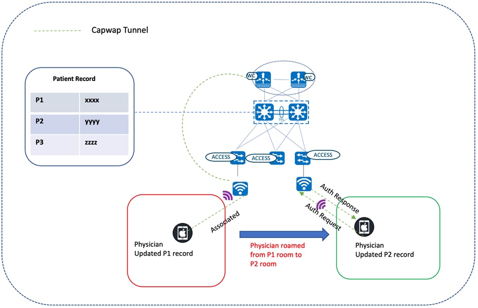
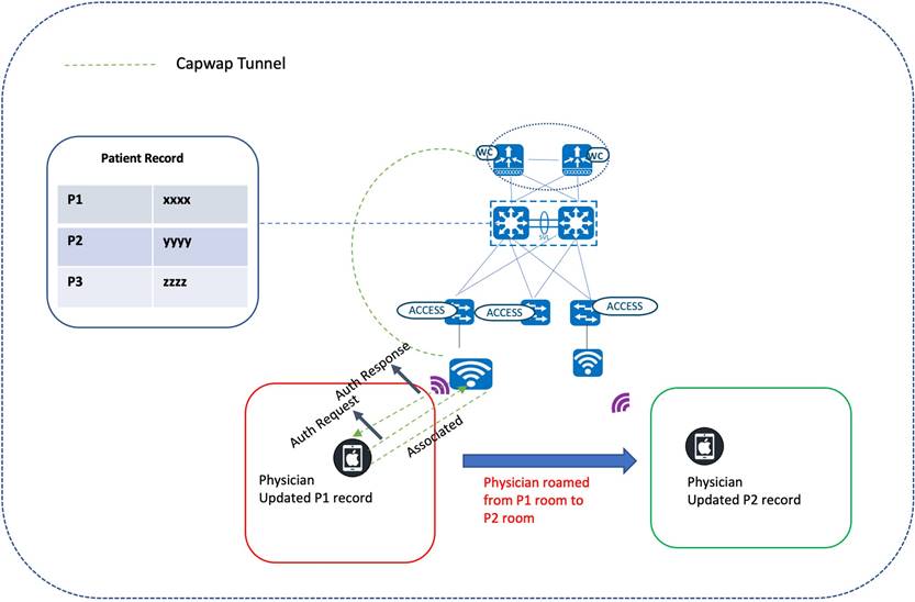
Wireless Roaming
Cisco wireless mobility solutions aim to improve the efficiency of healthcare services. Physicians on rounds could use their wireless laptops to update patient charts, which helps other staff members stay up-to-date with the latest information. Dieticians and nurses could check for the latest orders and review test results using wireless tablets. Patients would no longer need to wait in an admission queue. The registration clerk, armed with a wireless tablet, could help a patient complete registration while they wait to be seen.
Seamless mobility for a large number of clients is essential for supporting uninterrupted voice and data services. Fast roaming, such as CCKM and 802.11r/k/v, is enabled for this vertical. 802.11r, which is the IEEE standard for fast roaming, introduces a new roaming concept called Fast Transition (FT), where the initial handshake with the new AP is done even before the client roams to the target AP. The initial handshake allows the client and APs to do the Pairwise Transient Key (PTK) calculation in advance. These PTK keys are applied to the client and AP after the client sends a reassociation request or response exchange with the new target AP.
The FT key hierarchy is designed to allow clients to make fast BSS transitions between APs without requiring reauthentication at every AP. For a client to move from its current AP to a target AP using the FT protocols, the message exchanges are performed using one of the following two methods:
● Over-the-Air: The client communicates directly with the target AP using IEEE 802.11 authentication with the FT authentication algorithm.
● Over-the-DS: The client communicates with the target AP through the current AP. Client and target AP communication is carried in FT action frames between the client and the current AP, which are then sent through the controller.
Traffic Optimization
AutoQoS
As more and more interactive applications use wireless infrastructures, QoS becomes increasingly important. QoS allows network managers to establish SLAs with network users. It enables more efficient network resource sharing, expedites the handling of mission critical applications, and prioritizes time-sensitive multimedia and voice application traffic. QoS does this by:
● Reserving dedicated bandwidth for critical users and applications
● Controlling jitter and latency (required by real-time traffic)
● Managing and minimizing network congestion
● Shaping network traffic to smooth traffic flow
● Setting network traffic priorities
In a healthcare environment, QoS implementation is a policy decision and the applications used in different environments will dictate their QoS policy.
Catalyst Center enables the provision of the AutoQoS Fastlane during SSID creation for the prioritization of the traffic originating from Apple clients.
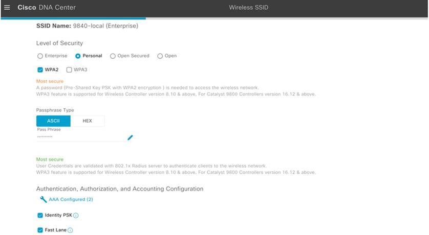
Catalyst Center pushes the following configurations to the wireless controller during wireless controller provisioning:
wireless profile policy 9840-local_Floor1_NF_5bfebcd0
aaa-override
accounting-list default
autoqos mode fastlane
cts inline-tagging
cts role-based enforcement
description 9840-local_Floor1_NF_5bfebcd0
dhcp-tlv-caching
exclusionlist timeout 180
http-tlv-caching
radius-profiling
service-policy input platinum-up
service-policy output platinum
vlan Vlan510
Various built-in AutoQoS profiles are classified into different macros based on the traffic characterization:
● Enterprise
● Voice
● Guest
MQoS
As part of the NBAR2-based Application QoS policy on IOS-XE based wireless controllers, Catalyst Center provisions the Cisco Validated Design Queuing profile.
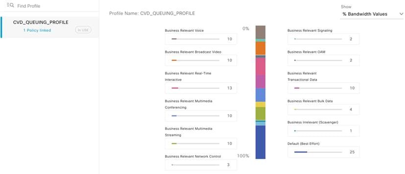
Catalyst Center bases its marking, queuing, and dropping treatments on IETF RFC 4594, as well as the business relevance category that you assign to the application. For more information, see "Application Policies" in the Cisco Catalyst Center User Guide.
The following is a sample configuration:
9840-hca#show policy-map 9840-local_DNA-MARKING_0550e02f Policy Map 9840-local_DNA-MARKING_0550e02f
Class 9840-local_VOICE_0550e02f
set dscp ef
Class 9840-local_TRANS_DATA_0550e02f
set dscp af21
Class 9840-local_SCAVENGER_0550e02f
set dscp cs1
Class 9840-local_REALTIME_0550e02f
set dscp cs4
Class 9840-local_MM_STREAM_0550e02f
set dscp af31
Class 9840-local_BROADCAST_0550e02f
set dscp cs5
Class 9840-local_OAM_0550e02f
set dscp cs2
Class 9840-local_SIGNALING_0550e02f
set dscp cs3
Class 9840-local_MM_CONF_0550e02f
set dscp af41
Class 9840-local_CONTROL_0550e02f
set dscp cs6
Class 9840-local_BULK_DATA_0550e02f
set dscp af11
Class class-default
set dscp default
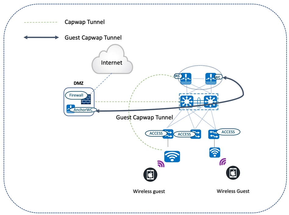
Guest Anchoring
Wireless Guest Access
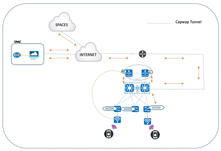
Catalyst Center offers a wireless guest anchoring solution that does the following:
● Provisions the servicing wireless controllers as foreign controllers.
● Provisions the anchor controllers in the DMZ area (which acts as a gateway for guest users to reach the internet).
Guest traffic is tunneled via CAPWAP all the way from the servicing APs attached to the foreign controller to the anchor controller in the DMZ.
Foreign Guest
wireless profile policy guest-camp_Global_GA_7ae528ce
aaa-override
accounting-list default
description guest-camp_Global_GA_7ae528ce
dhcp-tlv-caching
exclusionlist timeout 180
http-tlv-caching
mobility anchor 90.1.1.7 priority 3
mobility anchor 90.1.1.8 priority 3
nac
service-policy input silver-up
service-policy output silver
no shutdown
!
wlan guest-camp_Global_GA_7ae528ce 18 guest-campus2
mac-filtering dnac-cts-guest-camp-1d1eb5df
no security ft adaptive no security wpa
no security wpa wpa2
no security wpa wpa2 ciphers aes
no security wpa akm dot1x
no shutdown
Anchor Guest
wireless profile policy guest-camp_Global_GA_7ae528ce
aaa-override
accounting-list default
description guest-camp_Global_GA_7ae528ce
dhcp-tlv-caching
exclusionlist timeout 180
http-tlv-caching
mobility anchor
nac
service-policy input silver-up
service-policy output silver
vlan Vlan91
no shutdown
!
wlan guest-camp_Global_GA_7ae528ce 22 guest-campus2
mac-filtering dnac-cts-guest-camp-1d1eb5df
no security ft adaptive
no security wpa
no security wpa wpa2
no security wpa wpa2 ciphers aes
no security wpa akm dot1x
no shutdown
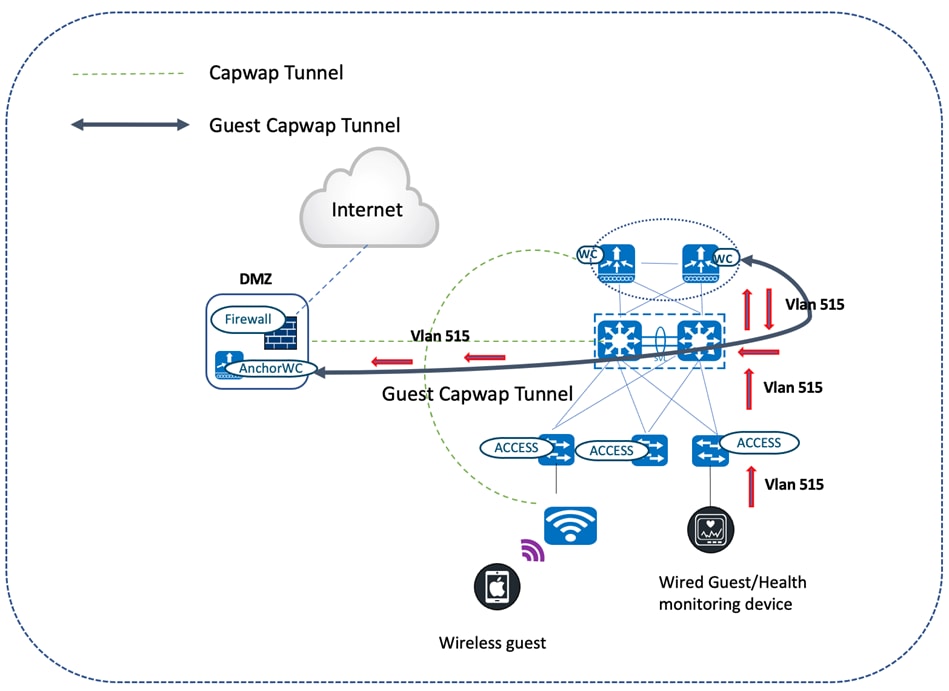
Wired Guest Access
Wired guest access allows the wired port to connect to the manufacturer's or vendor's website for equipment maintenance, software, or firmware updates. Wired guest sessions are connected to the designated wired Ethernet ports and are completed using the configured authentication method (OPEN or Webauth). Wired guest sessions are terminated at the guest anchor controller in the DMZ through the CAPWAP tunnel originating from the guest foreign controller. Wired guest access is a two-controller solution with a guest anchor and a guest foreign controller. This type of deployment isolates the wired guest traffic from enterprise user traffic.
Foreign Guest
wireless profile policy PP_PGN-VIP-Wired
guest-lan enable-session-timeout
mobility anchor 90.1.1.8 priority 3
no shutdown
!
guest-lan profile-name PP_PGN-VIP-Wired 1 wired-vlan 515
no security web-auth
no shutdown
Anchor Guest
wireless profile policy PP_PGN-VIP-Wired
guest-lan enable-session-timeout
mobility anchor
vlan Vlan91
no shutdown
!
guest-lan profile-name PP_PGN-VIP-Wired 1
no security web-auth
no shutdown
Location Services
CMX and Cisco Spaces
Patient and healthcare device mobility is essential for high-quality patient care. Catalyst Center addresses these use cases with the CMX and Cisco Spaces integration, which tracks mobile assets like Wi-Fi tags, laptops, and phones.
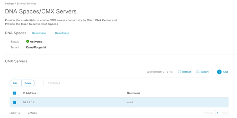
The Cisco Spaces connector is installed on premises, which establishes an NMSP connection with the wireless controllers. Via this connection, aggregated data is relayed from the controllers and APs to Cisco Spaces. For information on setting up the Cisco Spaces connector, see the "Prerequisites" chapter in the Cisco Spaces: Connector Configuration Guide.
The Cisco Spaces connector/CMX is then mapped to the corresponding site in Catalyst Center's Wireless Network Settings page and provision the wireless controller to push the NMSP mapping to the Cisco Spaces connector on the wireless controller.
The APs are placed under the corresponding floors in the wireless maps configured in Catalyst Center's Network Hierarchy page. The same positioning of the APs is reflected in Cisco Spaces (in the Detect and Locate application). This application also tracks the clients associated to APs, as well as rogue APs, rogue clients, and interferers. The medical assets that have Wi-Fi asset tags attached to them can also be tracked in Cisco Spaces.
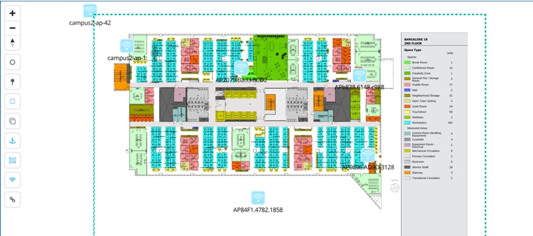
The following topology depicts the logical flow of events and illustrates how Cisco Spaces and Catalyst Center are in sync:
● Catalyst Center is registered with Cisco Spaces.
● The wireless controller is registered with the Cisco Spaces connector.
● The Cisco Spaces connector forwards the aggregate details of APs and endpoints in the WLAN to Cisco Spaces.
● Catalyst Center's wireless maps are synced with Cisco Spaces.
● Cisco Space's Detect and Locate application forwards client map locations to the wireless maps maintained by Catalyst Center. For more information on Catalyst Center's integration with Cisco Spaces, see "Catalyst Center Integration" in the Cisco Spaces Configuration Guide.
High Availability
AP/Client SSO
Healthcare networks need to be resilient enough to provide continuous service. The high availability feature (AP SSO/Client SSO) is especially important to achieve this goal. Catalyst Center allows you to form an RP+RMI HA setup, which involves connecting two physical wireless controllers to form an active and standby pair with a single control/data plane. At any given time, there is a single CAPWAP tunnel between an AP and the active wireless controller. Also, the AP database for both the active and standby wireless controllers are in sync. Whenever a failover occurs, the standby wireless controller becomes the new active wireless controller. And since it already has the details of the connected AP in its database, the APs never have to go down and reestablish the CAPWAP tunnel. It results in a seamless failover where the AP continues to stay up. Similarly, the wireless clients in the RUN state are synced between the active and standby wireless controllers. During a failover, clients do not have to reassociate and are able to maintain a continuous session.
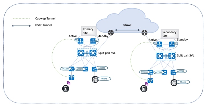
N+1 SSO
Catalyst Center provides N+1 HA functionality, offering controller redundancy of controllers across multiple geographies. Unlike the RP+RMI HA setup, AP SSO and client SSO are not supported by N+1 setups. Whenever the primary controller fails, the APs disconnect from it and then join the secondary backup controller, which results in the restart of the CAPWAP state machine. After the primary controller resumes operation, the APs disconnect from the backup controller and rejoin the primary wireless controller. For more information, see "Catalyst Center Configuration for N+1 High Availability" in the Cisco Catalyst 9800 Wireless Controller N+1 High Availability White Paper.
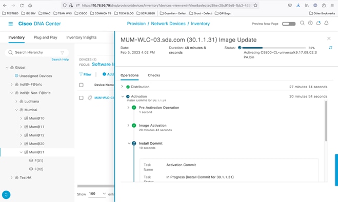
In-Service Software Upgrade
Catalyst Center offers In-Service Software Upgrade (ISSU), which allows you to upgrade an HA-enabled wireless controller to a newer Catalyst Center version without disrupting data forwarding in your network. If you use ISSU, note that you can only upgrade to a newer major version. (You can't upgrade to a point or patch version.)
You complete the following tasks when using ISSU:
1. Onboard the controller's software image to flash memory.
2. Download the AP image to the relevant AP.
3. Install the controller's software image.
4. Commit your changes.
For more information, see "Upgrade a Software Image with ISSU" in the Cisco Catalyst Center User Guide.
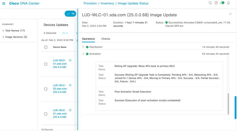
Rolling AP Upgrade
HA isn't exclusive to wireless controllers. Catalyst Center extends HA to APs via the rolling AP upgrade feature. When enabled, this feature provides the following benefits:
● Allows for staggered AP upgrades in an N+1 topology.
● Ensures that continuous service is available to users connected to the network while an upgrade is taking place.
● Automatically selects candidate APs using RRM-based neighbor information and the user-specified percentage for the upgrade: 5, 15 (default), or 25.
For more information, see "About N+1 Rolling AP Upgrade" in the Cisco Catalyst Center User Guide.
Telemetry-Based Assurance
Healthcare organizations have large-scale device sites with multiple endpoints. Administrators have indicated that managing, tracking, and monitoring these sites can be tedious. Cisco Catalyst Assurance simplifies these tasks by continually assessing the health of your network and its endpoints. The Telemetry Data Logger (TDL) collects streaming telemetry data from the devices managed by Catalyst Center, allowing network administrators to monitor network nodes and both wired and wireless clients in real-time. Armed with this data, administrators can troubleshoot any technical issues that arise.
Coexistence of Legacy and Wi-Fi 6-Capable Clients
The number of wireless devices has surged in recent years. New advancements in wireless transmission techniques play a pivotal role in ensuring the efficiency of network services. Legacy stations and the latest Wi-Fi stations must coexist, because upgrading client devices to the latest Wi-Fi standard is a multiyear effort. The 802.11ax standard supports backward compatibility, providing a cohesive environment for older and newer Wi-Fi standards. It is important to implement a deployment where WPA2 and WPA3 coexist to enable a natural transition from WPA2 to WPA3. The Wi-Fi alliance introduced transition modes where WPA2 and WPA3 SSIDs can connect simultaneously. To achieve the simultaneous connection, WPA3 transition mode, also known as mixed mode, is enabled under the enterprise and personal modes. In this mode, WPA2-only and WPA3-only capable clients can connect to the Wi-Fi as follows:
● WPA3-capable clients use WPA3-Enterprise’s 802.1X-SHA256 AKM. WPA2-capable clients use WPA2-Enterprise’s 802.1X SHA1 or 802.1X-SHA256.
● WPA3-capable clients use WPA3-Personal’s SAE. WPA2-capable clients use WPA2-Personal’s PSK.
Note: This mode applies to 2.4-GHz and 5-GHz bands.
The following steps create a WLAN with WPA2+WPA3-Enterprise transition mode with 6 GHz:
wlan wlan-name wlan-id SSID-name
security wpa wpa3
security wpa wpa2
security wpa akm dot1x-sha256
security wpa akm dot1x
radio policy dot11 6ghz
radio policy dot11 24ghz
radio policy dot11 5ghz
no shutdown
RF-Based Automatic AP Load Balancing
RF-based automatic load balancing is an alternative to the existing site tag-based load balancing for APs. Traditionally, APs are assigned to Wireless Network Control Daemon (WNCD) instances running on the wireless controller, which sometimes leads to CPU or memory issues due to uneven assignment of APs to the available WNCD instances. To mitigate human error, APs are load balanced across the WNCD using neighbor report-based AP grouping, primarily managed by RRM. When this feature is enabled, it forms AP clusters based on the RSSI received from AP neighbor reports. These clusters or neighborhoods are further split into subneighborhoods and smaller areas. The resulting groups of APs are then distributed evenly across the WNCD processes. The AP load balancing takes effect only after a controller reboot or through an AP CAPWAP reset triggered by the ap neighborhood load-balance apply command. When the RF-based automatic AP load balancing feature is active, it overrides other site tag-based load balancing. The RF-based load balancing algorithm has two phases: enablement (computation) and application of the algorithm. To schedule daily, weekly, or monthly computation based on the calendar profile start time expiry, use the ap neighborhood calendar-profile command. To start the algorithm on demand, use the ap neighborhood load-balance start command. The RF-based automatic AP load balancing feature can be applied by controller reload or by using the ap neighborhood load-balance apply command when the wireless load-balance ap method rf configuration is enabled. For information on prerequisites, restrictions, and configurations, see the Cisco Catalyst 9800 Series Wireless Controller Software Configuration Guide.
IOT Wireless Service Coexistence with iCAP
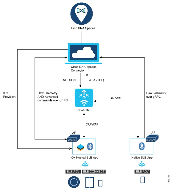
Intelligent Capture (iCAP) and IOT services (wireless) in Cisco Spaces work together to enhance the monitoring, troubleshooting, and location services within a Cisco wireless network, especially in environments with high density or complex deployments with numerous IoT devices. Dual gRPC for iCAP and Cisco Spaces plays a key role in optimizing the flow of telemetry data and operational commands between Cisco infrastructure, especially in high-performance wireless environments. gRPC Remote Procedure Call is an open-source, high-performance RPC framework that uses HTTP/2 for transport. Dual gRPC in Cisco environments means having two gRPC channels that permit parallel data streams between the controller and other devices like APs, Catalyst Center, or cloud-based systems. When combined, iCAP and Cisco Spaces powered by dual gRPC channels offer a highly efficient, scalable, and responsive wireless network management solution. Various components are involved in enabling IOT services. The Catalyst 9100 Series AP acts as a gateway between the IOT devices and Cisco Spaces.
● The Catalyst 9800 controller receives the BLE configuration from Cisco Spaces over NETCONF and passes the configuration to the AP over CAPWAP.
● The feedback path from the AP to the wireless controller is through CAPWAP, and from the Catalyst 9800 controller to Cisco Spaces through Telemetry data logger (TDL) telemetry streaming.
● The gRPC configuration from Cisco Spaces also goes through the Catalyst 9800 controller, and from there to the corresponding AP.
● The configuration sets up the gRPC channel between the AP and Cisco Spaces.
● The AP sends the gRPC channel statistics to the Catalyst 9800 controller. You can view these statistics on the Catalyst 9800 controller.
For prerequisites, see Cisco Spaces: IoT Service Configuration Guide (Wireless).
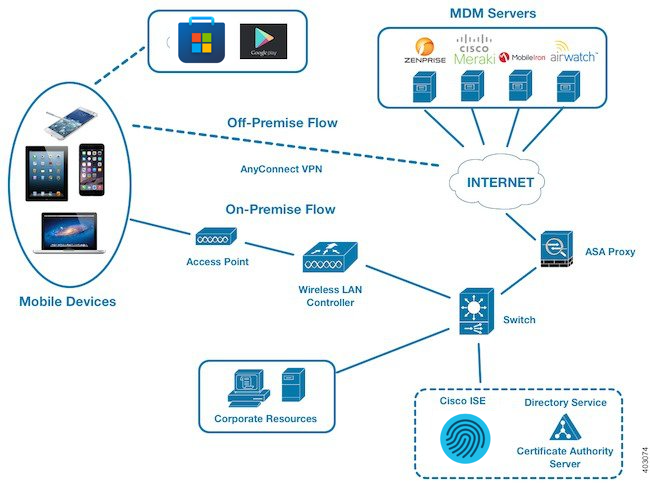
MDM, VPN, and Posture
Mobile Device Management (MDM), virtual private network (VPN), and posture assessment are key components used in securing mobile devices and network access in a healthcare environment.
MDM
An IT administrator of a healthcare provider uses MDM servers to secure, monitor, manage, and support mobile devices like laptops or mobile phones used by doctors, nurses, and administrative staff. These servers act as the policy server that controls the use of some applications on a mobile device (for example, an email application) in the deployed environment.
However, the network is the only entity that can provide granular access to endpoints based on access control lists (ACLs). Cisco ISE queries the MDM servers for the necessary device attributes to create ACLs that provide network access control for those devices.
When a device attempts to connect, Cisco ISE checks its compliance status with MDM and grants or denies access accordingly.
Cisco ISE integrates with various MDM providers like Cisco Meraki, Microsoft Intune, MobileIron, Airwatch, and Zenprise.
Configure MDM
1. MDM server setup:
◦ Ensure that your MDM server is up and running.
◦ Generate API credentials within your MDM server to allow communication with Cisco ISE.
2. Cisco ISE configuration:
◦ Log in to your Cisco ISE administration interface.
◦ Go to Administration > Network Resources.
◦ Under External MDM Servers, click Add.
◦ Enter the following MDM details:
Name: A descriptive name for the MDM server.
Server URL: The URL of your MDM server's API endpoint.
Certificate: Upload the certificate obtained from your MDM server.
API Credentials: Enter the API credentials generated earlier.
◦ Test Connection: Click Test Connection to verify the connectivity.
3. Configure endpoint profiles:
◦ Under Endpoint Profiles, create profiles to define different device types and compliance requirements.
◦ Assign attributes to each profile, such as device type, OS, and compliance rules.
4. Define authorization policies:
◦ Create policies under Policy Sets > Authorization Policies.
◦ Create rules that determine network access based on endpoint profiles and device posture.
◦ Define conditions that check if a device is compliant with the specified endpoint profile.
◦ Assign roles to compliant devices (such as network access and application access).
5. Test the integration:
◦ Enroll a test device using the MDM portal and attempt to access the network.
◦ Check if Cisco ISE correctly recognizes the device's compliance status and applies the appropriate policy.
VPN
Doctors, nurses, and administrative staff of hospitals and healthcare providers use VPN to remotely connect to the organization’s network and access resources (like patient records or billing data) when they are working from home or another location. Cisco ISE enforces policies based on user identity and device attributes, ensuring that only authorized users can access the VPN.
Configure VPN
1. Configure Cisco ISE:
◦ Define profiles for different types of devices (such as Windows laptops or iOS devices) that will access the VPN.
◦ Create authorization policies for granting or denying VPN access based on endpoint profiles, user attributes, and other criteria.
◦ Set up Cisco ISE as a RADIUS server to authenticate VPN users.
2. Configure Cisco Secure Client:
◦ Install and deploy Cisco Secure Client on the devices that will connect to the VPN.
◦ Create VPN profiles for different types of VPN connections (such as remote access or site-to-site).
◦ Configure Cisco Secure Client to use Cisco ISE as the RADIUS server for authentication.
3. Test the integration:
◦ Attempt to connect to the VPN using a device with Cisco Secure Client installed.
◦ Verify that Cisco ISE successfully authenticates the user and grants VPN access based on the configured policies.
Cisco ISE Posture
IT administrators of healthcare organizations use Cisco ISE posture to assess the security and compliance status of devices (used by doctors, nurses, and administrative staff) that connect to the network. Posture evaluates various factors such as OS versions, antivirus status, and firewall settings. Based on these assessments, Cisco ISE enforces policies to restrict or grant access to network resources.
Configure Cisco ISE Posture
1. Create endpoint profiles:
◦ Define profiles for different types of devices (such as Windows laptops or iOS devices) that will connect to the network.
◦ Specify the posture requirements for each profile, such as minimum OS version, antivirus status, and firewall settings.
2. Create posture elements:
◦ Define individual posture elements that will be evaluated, such as OS version, antivirus status, firewall settings, and custom scripts.
◦ Configure the criteria for each posture element, specifying the desired values or conditions.
3. Create posture evaluation policies:
◦ Combine posture elements into policies that define the overall posture requirements for devices.
◦ Assign these policies to the endpoint profiles that you created in Step 1.
4. Configure authorization policies:
◦ Create or modify authorization policies that determine whether to grant or deny device access to network resources based on posture evaluation.
◦ Use the posture evaluation results as conditions in your authorization policies.
5. Test posture evaluation:
◦ Connect a device to the network and verify that Cisco ISE correctly evaluates its posture based on the defined policies.
◦ Ensure that the device is granted or denied access to network resources as expected.
Posture Flow
1. The IT administrator of the healthcare provider configures the required policies in the MDM server used by the organization.
2. The IT administrator configures Cisco ISE with the necessary authentication methods and authorization policies to grant network access to doctors, nurses, and administrative staff.
3. The IT administrator configures the posture conditions for each device type according to the organization’s requirements.
4. The IT administrator provisions the organization’s assets by enrolling with the MDM server and predeploys the VPN and posture agent (Cisco Secure Client) so that users can log in to the network remotely.
5. An end user (doctor, nurse, or administrative staff) connects to the organization’s network through VPN. Cisco ISE performs the posture assessment of the device. Once compliant, Cisco ISE queries the MDM server for the MDM compliance before granting access to the network.
Technical References
● Cisco Validated Profile: Wireless Healthcare Vertical
● Validated Profile: Cisco SD-Access Healthcare Vertical
● Cisco AI Endpoint Analytics: A New Path Forward White Paper
● High Availability Using Patch and Rolling AP Upgrade on Cisco Catalyst 9800 Wireless Controllers
● Ascertain Methods for 802.11 WLAN and Fast-Secure Roaming on CUWN