Fabric Initialization and Switch Discovery

This chapter contains the following sections:

Initializing the Fabric

About Fabric Initialization

You can build a fabric by adding switches to be managed by the APIC and then validating the steps using the GUI, the CLI, or the API.


Note

Before you can build a fabric, you must have already created an APIC cluster over the out-of-band network.


Fabric Topology (Example)

An example of a fabric topology is as follows:

  • Two spine switches (spine1, spine2)

  • Two leaf switches (leaf1, leaf2)

  • Three instances of APIC (apic1, apic2, apic3)

The following figure shows an example of a fabric topology.

Figure 1. Fabric Topology Example


Connections: Fabric Topology

An example of the connection details for the fabric topology is as follows:

Name Connection Details

leaf1

eth1/1 = apic1 (eth2/1)

eth1/2 = apic2 (eth2/1)

eth1/3 = apic3 (eth2/1)

eth1/49 = spine1 (eth5/1)

eth1/50 = spine2 (eth5/2)

leaf2

eth1/1 = apic1 (eth 2/2)

eth1/2 = apic2 (eth 2/2)

eth1/3 = apic3 (eth 2/2)

eth1/49 = spine2 (eth5/1)

eth1/50 = spine1 (eth5/2)

spine1

eth5/1 = leaf1 (eth1/49)

eth5/2 = leaf2 (eth1/50)

spine2

eth5/1 = leaf2 (eth1/49)

eth5/2 = leaf1 (eth1/50)

Multi-Tier Fabric Topology (Example)

3-tier Core-Aggregation-Access architectures are common in data center network topologies. As of the Cisco APIC Release 4.1(1), you can create a multi-tier ACI fabric topology that corresponds to the Core-Aggregation-Access architecture, thus mitigating the need to upgrade costly components such as rack space or cabling. The addition of a tier-2 leaf layer makes this topology possible. The tier-2 leaf layer supports connectivity to hosts or servers on the downlink ports and connectivity to the leaf layer (aggregation) on the uplink ports.

In the multi-tier topology, the leaf switches initially have uplink connectivity to the spine switches and downlink connectivity to the tier-2 leaf switches. To make the entire topology an ACI fabric, all ports on the leaf switches connecting to tier-2 leaf fabric ports must be configured as fabric ports (if not already using the default fabric ports). After APIC discovers the tier-2 leaf switch, you can change the downlink port on the tier-2 leaf to a fabric port and connect to an uplink port on the middle layer leaf.


Note

If you are not using the default fabric ports to connect leaf switches to tier-2 leaf, you must convert the leaf ports from downlink to uplink (leaf switch reload required). For more information about changing port connectivity, see the Access Interfaces chapter of the Cisco APIC Layer 2 Networking Configuration Guide.


The following figure shows an example of a multi-tier fabric topology.

Figure 2. Multi-Tier Fabric Topology Example

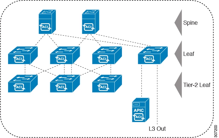
While the topology in the above image shows the Cisco APIC and L3Out/EPG connected to the leaf aggregation layer, the tier-2 leaf access layer also supports connectivity to APICs and L3Out/EPGs.


Note

Only Cisco Nexus 9000 Series switches with model numbers that end in EX, and later are supported as tier-2 leaf switches and as leaf switches, if there are tier-2 leaf switches attached to them. See the table below.

Tier-2 leaf switches attached to remote leaf switches are not supported.


Table 1. Supported Switches and Port Speeds for Multi-Tier Architecture

Switch

Maximum supported downlink port* (as tier-2 leaf)

Maximum supported fabric ports (as tier-2 leaf)

Maximum supported fabric ports (as tier-1 leaf)

Nexus 93180YC-EX

48x1/10/25-Gbps

4x40/100-Gbps

48 x 10/25-Gbps

6 x 40/100-Gbps

48 x 10/25-Gbps

6 x 40/100-Gbps

Nexus 93108TC-EX

48x100M/1/10G BASE-T

4x40/100-Gpbs

6 x 40/100-Gbps

6 x 40/100-Gbps

N9K-9348GC-FXP**

48 x 100M/1G BASE-T

4 x 10/25-Gbps

2 x 40/100-Gbps

4 x 10/25-Gbps

2 x 40/100-Gbps

N9K-93180YC-FX

48 x 1/10/25-Gbps

4x40/100-Gbps

48 x 10/25-Gbps

6 x 40/100-Gbps

48 x 10/25-Gbps

6 x 40/100-Gbps

N9K-93108TC-FX

48 x 100M/1/10G BASE-T

4x40/100-Gbps

6 x 40/100-Gbps

6 x 40/100-Gbps

N9K-93240YC-FX2

48x1/10/25-Gbps

10x40/100-Gbps

48x1/10/25-Gbps

12x40/100-Gbps

48x10/25-Gbps fiber ports

12x40/100-Gbps

N9K-C9336C-FX2

34 x 40/100-Gbps

36 x 40/100-Gbps

36 x 40/100-Gbps

N9K-C93216TC-FX2***

96 x 10G BASE-T

10 x 40/100-Gbps

12 x 40/100-Gbps

12 x 40/100-Gbps

N9K-C93360YC-FX2***

96 x 10/25-Gbps

10 x 40/100-Gbps

52 x 10/25Gbps

12 x 40/100Gbps

52 x 10/25Gbps

12 x 40/100Gbps

N9K-C9364C-GX

62 x 40/100-Gbps

62 x 40/100-Gbps

62 x 40/100-Gbps

* Last 2 original fabric ports cannot be used as downlink ports.

** If tier-2 leaf does not require much bandwidth, it can be used as tier-1 though it has fewer fiber ports. Copper port cannot be used as a fabric port.

*** Supported beginning with Cisco APIC Release 4.1(2).

Changing the External Routable Subnet

These procedures describe how to change the external routable subnet, if you find that you have to make changes to the information in the subnets or TEP table after you've made those configurations.


Note

Changing an external routable subnet configuration using multiple subnets is not supported.


Procedure


Step 1

Navigate to the area where you originally configured the external routable subnet.

  1. On the menu bar, click Fabric > Inventory.

  2. In the Navigation pane, click Pod Fabric Setup Policy.

  3. On the Fabric Setup Policy panel, double-click the pod where you originally configured the external routable subnet.

    The Fabric Setup Policy for a POD page for this pod appears.

  4. Locate the information for the subnets or TEP table, depending on the release of your APIC software:

    • For releases prior to 4.2(3), locate the Routable Subnets table.

    • For 4.2(3) only, locate the External Subnets table.

    • For 4.2(4) and later, locate the External TEP table.

Step 2

Locate the external routable subnet that you want to delete in the table and determine if the state of that subnet is set to active or inactive.

If the state is set to active, change the state to inactive:

  1. Double-click on the entry in the subnets or TEP table for the existing external routable subnet that you want to delete.

  2. Change the state for the subnet to inactive, then click Update.

Step 3

Delete the existing external routable subnet.

  1. Click on the entry in the subnets or TEP table for the existing external routable subnet that you want to delete.

  2. Click the trashcan icon at the top of the table, then click Yes in the pop-up confirmation window to delete the external routable subnet.

Step 4

Wait for at least 30 seconds, then configure a new external routable subnet.

  1. Click + in the subnets or TEP table to configure a new external routable subnet.

  2. Enter the IP address and Reserve Address, if necessary, and set the state to active or inactive.

    • The IP address is the subnet prefix that you wish to configure as the routeable IP space.

    • The Reserve Address is a count of addresses within the subnet that must not be allocated dynamically to the spine switches and remote leaf switches. The count always begins with the first IP in the subnet and increments sequentially. If you wish to allocate the Unicast TEP from this pool, then it must be reserved.

  3. Click Update to add the new external routable subnet to the subnets or TEP table.

  4. On the Fabric Setup Policy panel, click Submit.

Step 5

Verify that the new routable IP address is configured correctly.

Log into the APIC controller through the CLI and enter the following command:

apic1# avread | grep routableAddress

Output similar to the following should appear:

routableAddress   14.3.0.228              14.3.0.229              14.3.1.228
Step 6

Check the NAT entries created on the spine switch.

Log into the spine switch through the CLI and enter the following command:

spine1# show nattable

Output similar to the following should appear:


-----NAT TABLE---------
Private Ip  Routable Ip
----------  -----------
10.0.0.2    14.3.0.229 

10.0.0.1    14.3.0.228 

10.0.0.3    14.3.1.228 

Switch Discovery

About Switch Discovery with the APIC

The APIC is a central point of automated provisioning and management for all the switches that are part of the ACI fabric. A single data center might include multiple ACI fabrics; each data center might have its own APIC cluster and Cisco Nexus 9000 Series switches that are part of the fabric. To ensure that a switch is managed only by a single APIC cluster, each switch must be registered with that specific APIC cluster that manages the fabric.

The APIC discovers new switches that are directly connected to any switch it currently manages. Each APIC instance in the cluster first discovers only the leaf switch to which it is directly connected. After the leaf switch is registered with the APIC, the APIC discovers all spine switches that are directly connected to the leaf switch. As each spine switch is registered, that APIC discovers all the leaf switches that are connected to that spine switch. This cascaded discovery allows the APIC to discover the entire fabric topology in a few simple steps.

Switch Registration with the APIC Cluster


Note

Before you begin registering a switch, make sure that all switches in the fabric are physically connected and booted in the desired configuration. For information about the installation of the chassis, see http://www.cisco.com/c/en/us/support/cloud-systems-management/application-policy-infrastructure-controller-apic/products-installation-guides-list.html.


After a switch is registered with the APIC, the switch is part of the APIC-managed fabric inventory. With the Application Centric Infrastructure fabric (ACI fabric), the APIC is the single point of provisioning, management, and monitoring for switches in the infrastructure.


Note

The infrastructure IP address range must not overlap with other IP addresses used in the ACI fabric for in-band and out-of-band networks.


Switch Role Considerations

The following table specifies the default role for the switches for which you are able to change their role:

Table 2. Default Switch Roles

Switch Product ID

Default Role

First Release to Support a Role Change1

N9K-C9364C-GX

Leaf

5.1(3)

N9K-C9316D-GX

Spine

5.1(4)

1 Specifies the first release to support changing the role change for the indicated switch. Role changing for that switch is supported in all subsequent releases.

Registering an Unregistered Switch Using the GUI


Note

The infrastructure IP address range must not overlap with other IP addresses used in the ACI fabric for in-band and out-of-band networks.


Before you begin

Make sure that all switches in the fabric are physically connected and booted.

Procedure


Step 1

On the menu bar, choose Fabric > Inventory.

Step 2

In the Navigation pane, choose Fabric Membership.

Step 3

In the work pane, click the Nodes Pending Registration tab.

Switches in the Nodes Pending Registration tab table can have the following conditions:

  • A newly discovered but unregistered node has a node ID of 0 and has no IP address.

  • A manually entered (in Cisco Application Policy Infrastructure Controller (APIC)) but unregistered switch has an original status of Undiscovered until it is physically connected to the network. Once connected, the status changes to Discovered.

Step 4

In the Nodes Pending Registration table, locate a switch with an ID of 0 or a newly connected switch with the serial number you want to register.

Step 5

Right-click the row of that switch, choose Register, and perform the following actions:

  1. Verify the displayed Serial Number to determine which switch is being added.

  2. Configure or edit the following settings:

    Field

    Setting

    Pod ID

    Identifier of the pod where the node is located.

    Node ID

    A number greater than 100. The first 100 IDs are reserved for Cisco APIC appliance nodes.

    Note 

    We recommend that leaf nodes and spine nodes be numbered differently. For example, number spines in the 100 range (such as 101, 102) and number leafs in the 200 range (such as 201, 202).

    After the node ID is assigned, it cannot be updated. After the node has been added to the Registered Nodes tab table, you can update the node name by right-clicking the table row and choosing Edit Node and Rack Name.

    RL TEP Pool

    Tunnel endpoint (TEP) pool identifier for the node.

    Node Name

    The node name, such as leaf1 or spine3.

    Role

    The assigned node role. The options are:

    • spine

    • leaf

    • virtualleaf

    • virtualspine

    • remote leaf

    • tier-2-leaf

    If you choose a role other than the default role for the node, the node automatically reboots during the registration to change the role.

    Rack Name

    The name of the rack in which the node is installed. Choose Default, or choose Create Rack to add a name and description.

  3. Click Register.

Cisco APIC assigns an IP address to the node and the node is added to the Registered Nodes tab table. Next and if applicable, other nodes that are connected to this node are discovered and appear in the Nodes Pending Registration tab table.
Step 6

Continue to monitor the Nodes Pending Registration tab table. As more nodes appear, repeat these steps to register each new node until all installed nodes are registered.


Adding a Switch Before Discovery Using the GUI

You can add a switch description before the switch is physically connected to the network by following these steps:

Before you begin

Make sure that you know the serial number of the switch.

Procedure


Step 1

On the menu bar, choose Fabric > Inventory.

Step 2

In the Navigation pane, choose Fabric Membership.

Step 3

On the Registered Nodes or Nodes Pending Registration work pane, click the Actions icon, then click Create Fabric Node Member.

The Create Fabric Node Member dialog appears.

Step 4

Configure the following settings:

Field

Setting

Pod ID

Identify the pod where the node is located.

Serial Number

Required: Enter the serial number of the switch.

Node ID

Required: Enter a number greater than 100. The first 100 IDs are reserved for Cisco Application Policy Infrastructure Controller (APIC) appliance nodes.

Note 

We recommend that you number leaf nodes and spine nodes differently. For example, number leaf nodes in the 100 range (such as 101, 102) and number spine nodes in the 200 range (such as 201, 202).

After the node ID is assigned, it cannot be updated. After the node has been added to the Registered Nodes tab table, you can update the node name by right-clicking the table row and choosing Edit Node and Rack Name.

Switch Name

The node name, such as leaf1 or spine3.

Node Type

Choose the type (role) for the node. The options are:

  • leaf

    Put a check in one of the following boxes if applicable:

    • Is Remote: Specifies that the node is a remote leaf switch.

    • Is Virtual: Specifies that the node is virtual.

    • Is Tier-2 Leaf: The fabric node member (leaf switch) being created will take on the characteristics of a tier-2 leaf switch in a multi-tier architecture.

  • spine

    Put a check in the following box if applicable:

    • Is Virtual: Specifies that the node is virtual.

  • unknown

If you choose a role other than the default role for the node, the node automatically reboots during the registration to change the role.

VPC Pair

Optional. If the node is part of a vPC pair, choose the ID of the node with which to pair this node.

VPC Domain ID

Enter the vPC domain ID for the vPC pair. The range is from 1 to 1000. This field only appears if you entered a value for VPC Pair, and is required in that case.

The Cisco APIC adds the new node to the Nodes Pending Registration tab table.

What to do next

Connect the physical switch to the network. Once connected, the Cisco APIC matches the serial number of the physical switch to the new entry. Monitor the Nodes Pending Registration tab table until the Status for the new switch changes from Undiscovered to Discovered. Follow the steps in the Registering an Unregistered Switch Using the GUI section to complete the fabric initialization and discovery process for the new switch.

Auto Firmware Update on Switch Discovery

When Auto Firmware Update on Switch Discovery is enabled, APIC automatically updates the firmware of the new switch in the following scenarios:

  • A new switch discovery with a new node ID

  • A switch replacement with an existing node ID

  • An initialization and rediscovering of an existing node

In releases earlier than Cisco APIC Release 5.1(1), this feature was named Enforce Bootscript Version Validation and was located at Admin > Firmware > Infrastructure > Nodes. In Cisco APIC Release 5.1(1), the feature is renamed and moved to its current location.

Procedure


Step 1

On the menu bar, navigate to Fabric > Inventory > Fabric Membership > Auto Firmware Update.

Step 2

Check the Auto Firmware Update on Switch Discovery checkbox to enable the feature.

Step 3

Select the target firmware version for updating new switches in the Default Firmware Version drop-down list.

Note 

If the node ID of the new switch is part of a firmware update group under Admin > Firmware, such as a replacement scenario, the new switch is updated to the target version specified by the update group. Otherwise, it’s updated to the default firmware version specified in this procedure.

When the selected Default Firmware Version is “any,” this feature won’t update the firmware of a new switch that has an ID that isn’t part of a firmware update group. A new switch that has a node ID that is part of a firmware update group will be updated to the target version specified by the update group.

Step 4

Click Submit.


Switch Discovery Validation and Switch Management from the APIC

After the switches are registered with the APIC, the APIC performs fabric topology discovery automatically to gain a view of the entire network and to manage all the switches in the fabric topology.

Each switch can be configured, monitored, and upgraded from the APIC without having to access the individual switches.

Validating the Registered Switches Using the GUI

Procedure


Step 1

On the menu bar, navigate to Fabric > Inventory > Fabric Membership.

Step 2

In the Fabric Membership work pane, click the Registered Nodes tab.

The switches in the fabric are displayed in the Registered Nodes tab table with their node IDs. In the table, all the registered switches are displayed with the IP addresses that are assigned to them.

Validating the Fabric Topology

After all the switches are registered with the APIC cluster, the APIC automatically discovers all the links and connectivity in the fabric and discovers the entire topology as a result.

Validating the Fabric Topology Using the GUI

Procedure


Step 1

On the menu bar, navigate to Fabric > Inventory > Pod number.

Step 2

In the Work pane, click the Topology tab.

The displayed diagram shows all attached switches, APIC instances, and links.
Step 3

(Optional) Hover over any component to view its health, status, and inventory information.

Step 4

(Optional) To view the port-level connectivity of a leaf switch or spine switch, double-click its icon in the topology diagram.

Step 5

(Optional) To refresh the topology diagram, click the icon in the upper right corner of the Work pane.


Unmanaged Switch Connectivity in VM Management

The hosts that are managed by the VM controller (for example, a vCenter), can be connected to the leaf port through a Layer 2 switch. The only prerequisite required is that the Layer 2 switch must be configured with a management address, and this management address must be advertised by Link Layer Discovery Protocol (LLDP) on the ports that are connected to the switches. Layer 2 switches are automatically discovered by the APIC, and they are identified by the management address. To view the unmanaged switches in APIC, navigate to Fabric > Inventory > Fabric Membership and click the Unmanaged Fabric Nodes tab.

Maintenance Mode

Maintenance Mode

Following are terms that are helpful to understand when using maintenance mode:

  • Graceful Insertion and Removal (GIR): The operation used to isolate a switch from user traffic.

  • Maintenance mode: Used to isolate a switch from user traffic for debugging purposes. You can put a switch in maintenance mode by enabling the Maintenance (GIR) field in the Fabric Membership page in the APIC GUI, located at Fabric > Inventory > Fabric Membership (right-click on a switch and choose Maintenance (GIR)).

    If you put a switch in maintenance mode, that switch is not considered as a part of the operational ACI fabric infra and it will not accept regular APIC communications. Therefore, performing a firmware upgrade for a switch in this state is not supported, since it may fail or may get stuck in an incomplete status indefinitely if you attempt to perform a firmware upgrade on it while it is in this state.

The maintenance mode allows you to isolate a switch from the network with minimum service disruption. In the maintenance mode you can perform real-time debugging without affecting traffic.

You can use maintenance mode to gracefully remove a switch and isolate it from the network in order to perform debugging operations. The switch is removed from the regular forwarding path with minimal traffic disruption.

In graceful removal, all external protocols are gracefully brought down except the fabric protocol (IS-IS) and the switch is isolated from the network. During maintenance mode, the maximum metric is advertised in IS-IS within the Cisco Application Centric Infrastructure (Cisco ACI) fabric and therefore the leaf switch in maintenance mode does not attract traffic from the spine switches. In addition, all front-panel interfaces on the switch are shutdown except for the fabric interfaces. To return the switch to its fully operational (normal) mode after the debugging operations, you must recommission the switch. This operation will trigger a stateless reload of the switch.

In graceful insertion, the switch is automatically decommissioned, rebooted, and recommissioned. When recommissioning is completed, all external protocols are restored and maximum metric in IS-IS is reset after 10 minutes.

The following protocols are supported:

  • Border Gateway Protocol (BGP)

  • Enhanced Interior Gateway Routing Protocol (EIGRP)

  • Intermediate System-to-Intermediate System (IS-IS)

  • Open Shortest Path First (OSPF)

  • Link Aggregation Control Protocol (LACP)

Protocol Independent Multicast (PIM) is not supported.

Important Notes

  • If a border leaf switch has a static route and is placed in maintenance mode, the route from the border leaf switch might not be removed from the routing table of switches in the ACI fabric, which causes routing issues.

    To work around this issue, either:

    • Configure the same static route with the same administrative distance on the other border leaf switch, or

    • Use IP SLA or BFD for track reachability to the next hop of the static route

  • Upgrading or downgrading a switch in maintenance mode is not supported.

  • While the switch is in maintenance mode, the Ethernet port module stops propagating the interface related notifications. As a result, if the remote switch is rebooted or the fabric link is flapped during this time, the fabric link will not come up afterward unless the switch is manually rebooted (using the acidiag touch clean command), decommissioned, and recommissioned.

  • While the switch is in maintenance mode, CLI 'show' commands on the switch show the front panel ports as being in the up state and the BGP protocol as up and running. The interfaces are actually shut and all other adjacencies for BGP are brought down, but the displayed active states allow for debugging.

  • For multi-pod, IS-IS metric for redistributed routes should be set to less than 63. To set the IS-IS metric for redistributed routes, choose Fabric > Fabric Policies > Pod Policies > IS-IS Policy.

  • Existing GIR supports all Layer 3 traffic diversion. With LACP, all the Layer 2 traffic is also diverted to the redundant node. Once a node goes into maintenance mode, LACP running on the node immediately informs neighbors that it can no longer be aggregated as part of port-channel. All traffic is then diverted to the vPC peer node. 


Removing a Switch to Maintenance Mode Using the GUI

Use this procedure to remove a switch to maintenance mode using the GUI. During the removal of a switch to maintenance mode, the out-of-band management interfaces will remain up and accessible.

Procedure


Step 1

On the menu bar, choose Fabric > Inventory.

Step 2

In the navigation pane, click Fabric Membership.

Step 3

In the Registered Nodes table in the work pane, right-click the row of the switch to be removed to maintenance mode and select Maintenance (GIR).

Step 4

Click OK.

The gracefully removed switch displays Maintenance in the Status column.


Inserting a Switch to Operational Mode Using the GUI

Use this procedure to insert a switch to operational mode using the GUI.

Procedure


Step 1

On the menu bar, choose Fabric > Inventory.

Step 2

In the navigation pane, click Fabric Membership.

Step 3

In the Registered Nodes table in the work pane, right-click the row of the switch to be inserted to operational mode and select Commision.

Step 4

Click Yes.