
New and Changed Information
The following table provides an overview of the significant changes up to this current release. The table does not provide an exhaustive list of all changes nor of the new features up to this release.
| Release Version | Feature | Description |
|---|---|---|
|
NDFC release 12.1.3 |
Reorganized content |
Content within this document was originally provided in the Cisco NDFC-Fabric Controller Configuration Guide or the Cisco NDFC-SAN Controller Configuration Guide. Beginning with release 12.1.3, this content is now provided solely in this document and is no longer provided in those documents. |
|
NDFC release 12.1.3 |
Introduction of NPV configuration wizard to NDFC. |
You can configure NPV links using the new NPV configuration wizard beginning with NDFC release 12.1.3. |
SAN Links
Cisco SAN Controller allows you to configure FCIP, Port channels on SAN Fabrics. You can also monitor the ISL traffic and errors, and view the performance of NPV links from the Cisco Nexus Dashboard Fabric Controller Web UI.
ISL and Port Channels
The ISL Traffic and Errors window is displayed. The table shows the ISLs and Port channels configured on SAN Fabrics. You can use the drop-down to filter the view by 24 hours, Week, Month, and Year.
Click on the trend icon in the Name column to view the graphical representation.
You can perform the following operations from the Actions drop-down list:
Configuring FCIP
To configure FCIP, perform the following steps:
-
Choose Configure FCIP from the Actions drop-down list.
The page displays the tasks to configure FCIP using the FCIP Wizard.

FCIP is not supported on Cisco MDS 9000 24/10-Port SAN Extension Module.
-
On the Select Switch Pair screen, select two MDS switches from the drop-down list to connect via FCIP.
Each switch must have an Ethernet port that is connected to an IP network to function correctly. Note In the case of a federation setup, both switches must belong to the fabrics that are discovered or managed by the same server.
-
Click Next to select the Ethernet ports.
-
Select the Ethernet ports to be used in FCIP ISL between the selected switches.
Down ports must be enabled to function correctly. Security can be enforced for unconfigured 14+2, 18+4, 9250i and SSN16 Ethernet ports.
-
Enter the Ethernet ports IP addresses and specify the IP Routes if the port addresses are in a different subnet.
Click Next to apply the changes to IP Address and IP Route.
-
Click Next to specify Tunnel properties.
-
Specify the following parameters to tunnel the TCP connections.
Enter the parameters.
-
Max Bandwidth: Enter the number between 1 to 10000. The unit is Mb.
-
Min Bandwidth: Enter the minimum bandwidth value. The unit is Mb.
-
Estimated RTT(RoundTrip Time): Enter the number between 0 to 300000. The unit is us. Click Measure to measure the roundtrip time.
-
Write Acceleration: Check the check box to enable the write acceleration.
If Write Acceleration is enabled, ensure that flows will not load balance across multiple ISLs.
-
Enable Optimum Compression: Check the check box to enable the optimum compression.
-
Enable XRC Emulator: Check the check box to enable XRC emulator.
-
Connections: Enter the number of connections from 0 to 100.
-
-
Click Next to create FCIP ISL.
-
Enter the Profile ID and Tunnel ID for the switch pair, and select the FICON Port Address from the drop-down list.
-
Click View Configured to display the Profiles and Tunnels information.
-
Select the Trunk Mode from non-Trunk, trunk, and auto. Specify the Port VSAN for non-Trunk and auto, and allowed VSAN List for Trunk tunnel.
-
Click Next to the last summary page.
The Summary view displays what you have selected in the previous steps.
-
Click Finish to configure FCIP.
Port Channels
Port Channels Overview
Port Channels refer to the aggregation of multiple physical interfaces into one logical interface to provide higher aggregated bandwidth, load balancing, and link redundancy (See below figure). Port Channels can connect to interfaces across switching modules, so a failure of a switching module cannot bring down the Port Channel link.
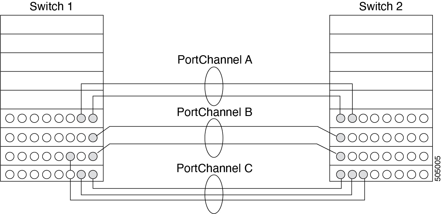
Port Channels on Cisco MDS 9000 Family switches allow flexibility in configuration. This illustrates three possible Port Channel configurations:
-
Port Channel A aggregates two links on two interfaces on the same switching module at each end of a connection.
-
Port Channel B also aggregates two links, but each link is connected to a different switching module. If the switching module goes down, traffic is not affected.
-
Port Channel C aggregates three links. Two links are on the same switching module at each end, while one is connected to a different switching module on switch 2.
Port Channeling and Trunking
Trunking is a commonly used storage industry term. However, the Cisco NX-OS software and switches in the Cisco MDS 9000 Family implement trunking and Port Channeling as follows:
-
Port Channeling enables several physical links to be combined into one aggregated logical link.
-
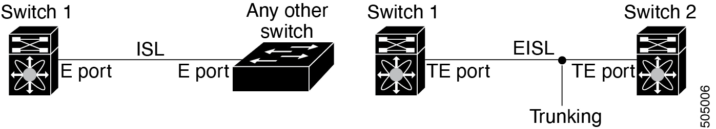
Trunking enables a link transmitting frames in the EISL format to carry (trunk) multiple VSAN traffic. For example, when trunking is operational on an E port, that E port becomes a TE port. A TE port is specific to switches in the Cisco MDS 9000 Family. An industry standard E port can link to other vendor switches and is referred to as a nontrunking interface (See !!!Dita2Adoc_MissingReference:!!! and !!!Dita2Adoc_MissingReference:!!!).
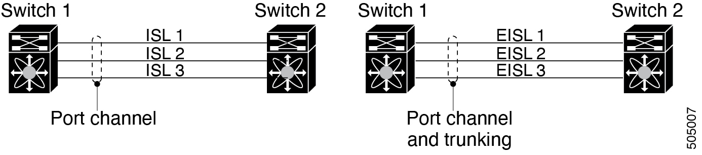
Port Channeling and trunking are used separately across an ISL.
Port Channeling-Interfaces can be channeled between the following sets of ports:
-
E ports and TE ports
-
F ports and NP ports
-
TF ports and TNP ports
-
Trunking-Trunking permits carrying traffic on multiple VSANs between switches.
-
Both Port Channeling and trunking can be used between TE ports over EISLs.
-
Load Balancing
Two methods support the load-balancing functionality:
-
Flow-based-All frames between a source and destination follow the same links for a given flow. That is, whichever link is selected for the first exchange of the flow is used for all subsequent exchanges.
-
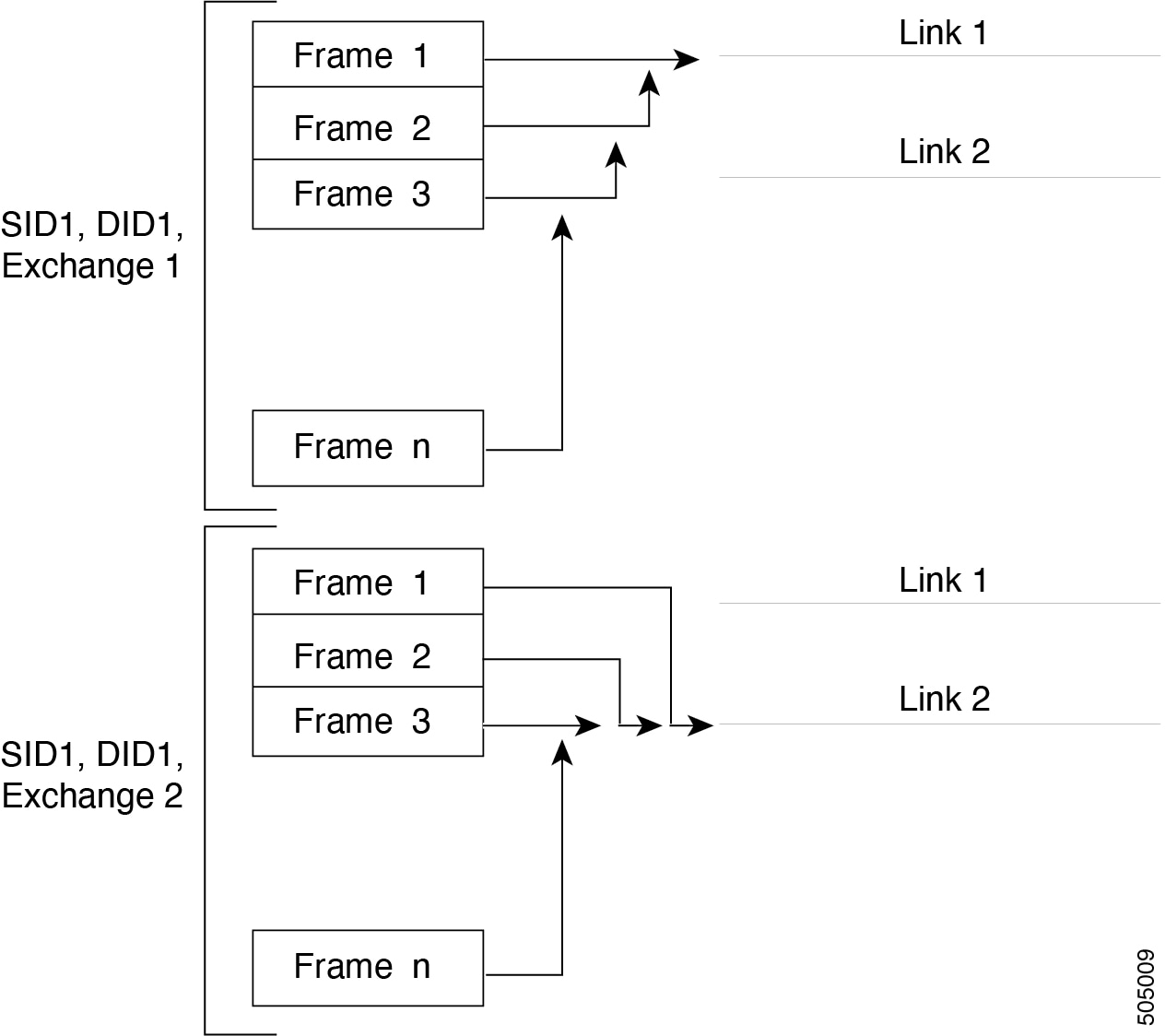
Exchange-based-The first frame in an exchange picks a link and subsequent frames in the exchange follow the same link. However, subsequent exchanges can use a different link. This provides more granular load balancing while preserving the order of frames for each exchange.
The following figure illustrates how a source ID 1 (SID1) and destination ID1 (DID1)-based load balancing works. When the first frame in a flow is received on an interface for forwarding, link 1 is selected. Each subsequent frame in that flow is sent over the same link. No frame in SID1 and DID1 utilizes link 2.
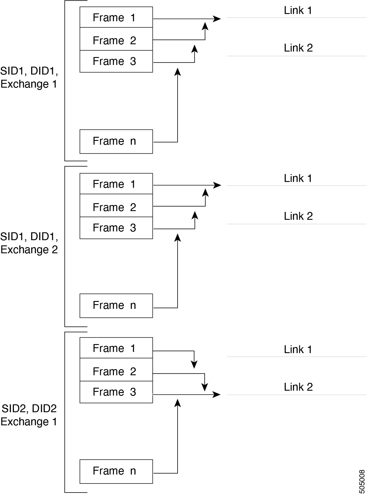
The following figure illustrates how exchange-based load balancing works. When the first frame in an exchange is received for forwarding on an interface, link 1 is chosen by a hash algorithm. All remaining frames in that particular exchange are sent on the same link. For exchange 1, no frame uses link 2. For the next exchange, link 2 is chosen by the hash algorithm. Now all frames in exchange 2 use link 2.
Port Channel Modes
You can configure each Port Channel with a channel group mode parameter to determine the Port Channel protocol behavior for all member ports in this channel group. The possible values for a channel group mode are as follows:
-
ON (default)-The member ports only operate as part of a Port Channel or remain inactive. In this mode, the Port Channel protocol is not initiated. However, if a Port Channel protocol frame is received from a peer port, the software indicates its nonnegotiable status. This mode is backward compatible with the existing implementation of Port Channels in releases prior to Release 2.0(1b), where the channel group mode is implicitly assumed to be ON. In Cisco MDS SAN-OS Releases 1.3 and earlier, the only available Port Channel mode was the ON mode. Port Channels that are configured in the ON mode require you to explicitly enable and disable the Port Channel member ports at either end if you add or remove ports from the Port Channel configuration. You must physically verify that the local and remote ports are connected to each other.
-
ACTIVE-The member ports initiate Port Channel protocol negotiation with the peer ports regardless of the channel group mode of the peer port. If the peer port, while configured in a channel group, does not support the Port Channel protocol, or responds with a nonnegotiable status, it defaults to the ON mode behavior. The ACTIVE Port Channel mode allows automatic recovery without explicitly enabling and disabling the Port Channel member ports at either end.
The following table compares ON and ACTIVE modes.
| ON Mode | ACTIVE Mode |
|---|---|
|
No protocol is exchanged. |
A Port Channel protocol negotiation is performed with the peer ports. |
|
Moves interfaces to the suspended state if its operational values are incompatible with the Port Channel. |
Moves interfaces to the isolated state if its operational values are incompatible with the Port Channel. |
|
When you add or modify a Port Channel member port configuration, you must explicitly disable (shut) and enable (no shut) the Port Channel member ports at either end. |
When you add or modify a Port Channel interface, the Port Channel automatically recovers. |
|
Port initialization is not synchronized. |
There is synchronized startup of all ports in a channel across peer switches. |
|
All misconfigurations are not detected as no protocol is exchanged. |
Consistently detect misconfigurations using a Port Channel protocol. |
|
Transitions misconfigured ports to the suspended state. You must explicitly disable (shut) and enable (no shut) the member ports at either end. |
Transitions misconfigured ports to the isolated state to correct the misconfiguration. Once you correct the misconfiguration, the protocol ensures automatic recovery. |
Port Channel Deletion
When you delete the Port Channel, the corresponding channel membership is also deleted. All interfaces in the deleted Port Channel convert to individual physical links. After the Port Channel is removed, regardless of the mode used (ACTIVE and ON), the ports at either end are gracefully brought down, indicating that no frames are lost when the interface is going down.
If you delete the Port Channel for one port, then the individual ports within the deleted Port Channel retain the compatibility parameter settings (speed, mode, port VSAN, allowed VSAN, and port security). You can explicitly change those settings as required.
-
If you use the default ON mode to avoid inconsistent states across switches and to maintain consistency across switches, then the ports shut down. You must explicitly enable those ports again.
-
If you use the ACTIVE mode, then the Port Channel ports automatically recover from the deletion.
Interfaces in a Port Channel
You can add or remove a physical interface (or a range of interfaces) to an existing Port Channel. The compatible parameters on the configuration are mapped to the Port Channel. Adding an interface to a Port Channel increases the channel size and bandwidth of the Port Channel. Removing an interface from a Port Channel decreases the channel size and bandwidth of the Port Channel.
This section describes interface configuration for a Port Channel and includes the following topics:
Interface Addition to a Port Channel
You can add a physical interface (or a range of interfaces) to an existing Port Channel. The compatible parameters on the configuration are mapped to the Port Channel. Adding an interface to a Port Channel increases the channel size and bandwidth of the Port Channel.
A port can be configured as a member of a static Port Channel only if the following configurations are the same in the port and the Port Channel:
-
Speed
-
Mode
-
Rate mode
-
Port VSAN
-
Trunking mode
-
Allowed VSAN list or VF-ID list
After the members are added, regardless of the mode (ACTIVE and ON) used, the ports at either end are gracefully brought down, indicating that no frames are lost when the interface is going down (see the "Generation 1 Port Channel Limitations" section on page -12).
Compatibility Check
A compatibility check ensures that the same parameter settings are used in all physical ports in the channel. Otherwise, they cannot become part of a Port Channel. The compatibility check is performed before a port is added to the Port Channel.
The check ensures that the following parameters and settings match at both ends of a Port Channel:
-
Capability parameters (type of interface, Gigabit Ethernet at both ends, or Fibre Channel at both ends).
-
Administrative compatibility parameters (speed, mode, rate mode, port VSAN, allowed VSAN list, and port security).
Ports in shared rate mode cannot form a Port Channel or a trunking Port Channel.
-
Operational parameters (remote switch WWN and trunking mode).
A port addition procedure fails if the capability and administrative parameters in the remote switch are incompatible with the capability and administrative parameters in the local switch. If the compatibility check is successful, the interfaces are operational and the corresponding compatibility parameter settings apply to these interfaces.
Suspended and Isolated States
If the operational parameters are incompatible, the compatibility check fails and the interface is placed in a suspended or isolated state based on the configured mode:
-
An interface enters the suspended state if the interface is configured in the ON mode.
-
An interface enters the isolated state if the interface is configured in the ACTIVE mode.
Forcing an Interface Addition
You can force the port configuration to be overwritten by the Port Channel. In this case, the interface is added to a Port Channel.
-
If you use the default ON mode to avoid inconsistent states across switches and to maintain consistency across switches, then the ports shut down. You have to explicitly enable those ports again.
-
If you use the ACTIVE mode, then the Port Channel ports automatically recover from the addition.
When Port Channels are created from within an interface, the force option cannot be used. After the members are forcefully added, regardless of the mode (ACTIVE and ON) used, the ports at either end are gracefully brought down, indicating that no frames are lost when the interface is going down.
Interface Deletion from a Port Channel
When a physical interface is deleted from the Port Channel, the channel membership is automatically updated. If the deleted interface is the last operational interface, then the Port Channel status is changed to a down state. Deleting an interface from a Port Channel decreases the channel size and bandwidth of the Port Channel.
-
If you use the default ON mode to avoid inconsistent states across switches and to maintain consistency across switches, then the ports shut down. You must explicitly enable those ports again.
-
If you use the ACTIVE mode, then the Port Channel ports automatically recover from the deletion.
After the members are deleted, regardless of the mode (ACTIVE and ON) used, the ports at either end are gracefully brought down, indicating that no frames are lost when the interface is going down.
Port Channel Protocols
In earlier Cisco SAN-OS releases, Port Channels required additional administrative tasks to support synchronization. The Cisco NX-OS software provides robust error detection and synchronization capabilities. You can manually configure channel groups or they can be automatically created. In both cases, the channel groups have the same capability and configurable parameters. Any change in configuration that is applied to the associated Port Channel interface is propagated to all members of the channel group.
A protocol to exchange Port Channel configurations is available in all Cisco MDS switches. This addition simplifies Port Channel management with incompatible ISLs. An additional autocreation mode enables ISLs with compatible parameters to automatically form channel groups without manual intervention.
The Port Channel protocol is enabled by default.
The Port Channel protocol expands the Port Channel functional model in Cisco MDS switches. It uses the exchange peer parameters (EPP) services to communicate across peer ports in an ISL. Each switch uses the information that is received from the peer ports along with its local configuration and operational values to decide if it should be part of a Port Channel. The protocol ensures that a set of ports is eligible to be part of the same Port Channel. They are only eligible to be part of the same Port Channel if all the ports have a compatible partner.
The Port Channel protocol uses two subprotocols:
-
Bringup protocol-Automatically detects misconfigurations so you can correct them. This protocol synchronizes the Port Channel at both ends so that all frames for a given flow (as identified by the source FC ID, destination FC ID and OX_ID) are carried over the same physical link in both directions. This helps make applications such as write acceleration, work for Port Channels over FCIP links.
-
Autocreation protocol-Automatically aggregates compatible ports into a Port Channel.
This section describes how to configure the Port Channel protocol and includes the following sections:
Channel Group Creation
Channel groups are not supported on internal ports in the Cisco Fabric Switch for HP c-Class BladeSystem and the Cisco Fabric Switch for IBM BladeSystem.
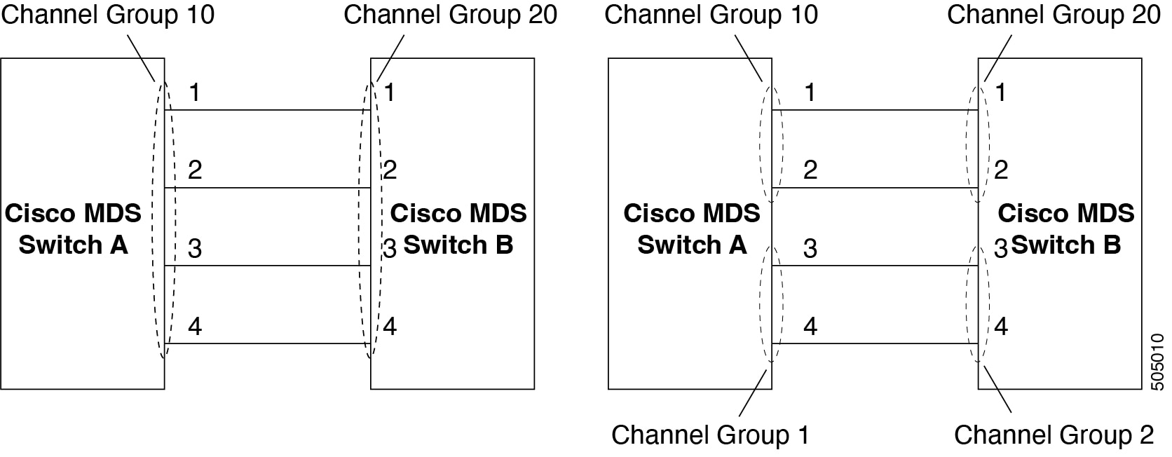
Assuming link A1-B1 comes up first (see Figure 1-9), that link is operational as an individual link. When the next link comes up, for example, A2-B2, the Port Channel protocol identifies if this link is compatible with link A1-B1 and automatically creates channel groups 10 and 20 in the respective switches. If link A3-B3 can join the channel groups (the Port Channels), the respective ports have compatible configurations. If link A4-B4 operates as an individual link, it is because of the incompatible configuration of the two end ports with the other member ports in this channel group.
The channel group numbers are selected dynamically, and as such, the administrative configuration of the ports forming the channel group at either end are applicable to the newly created channel group. The channel group number being chosen dynamically may be different across reboots for the same set of Port Channels based on the order of ports that are initialized in the switch.
The following table describes the differences between user-configured and auto-configured channel groups.
| User-Configured Channel Group | Autocreated Channel Group |
|---|---|
|
Manually configured by the user. |
Created automatically when compatible links come up between two compatible switches, if channel group autocreation is enabled in all ports at both ends. |
|
Member ports cannot participate in autocreation of channel groups. The autocreation feature cannot be configured. |
None of these ports are members of a user-configured channel group. |
|
You can form the Port Channel with a subset of the ports in the channel group. Incompatible ports remain in a suspended or isolated state depending on the ON or ACTIVE mode configuration. |
All ports included in the channel group participate in the Port Channel-no member port becomes isolated or suspended; instead, the member port is removed from the channel group when the link is found to be incompatible. |
|
Any administrative configuration that is made to the Port Channel is applied to all ports in the channel group, and you can save the configuration for the Port Channel interface. |
Any administrative configuration that is made to the Port Channel is applied to all ports in the channel group, but the configurations are saved for the member ports; no configuration is saved for the Port Channel interface. You can explicitly convert this channel group, if required. |
|
You can remove any channel group and add members to a channel group. |
You cannot remove a channel group, or add/remove any of its members. The channel group is removed when no member ports exist. |
Autocreation
The autocreation protocol has the following functionality:
-
A port is not allowed to be configured as part of a Port Channel when the autocreation feature is enabled. These two configurations are mutually exclusive.
-
Autocreation must be enabled in both the local and peer ports to negotiate a Port Channel.
-
Aggregation occurs in one of two ways:
-
A port is aggregated into a compatible autocreated Port Channel.
-
A port is aggregated with another compatible port to form a new Port Channel.
-
-
Newly created Port Channels are allocated from the maximum Port Channel (128 for Generation 1 or a combination of Generation 1 and Generation 2 switches, or 256 for Generation 2 switches) in a decreasing order based on availability. If all 128 (or 256) numbers are used up, aggregation is not allowed.
-
You cannot change the membership or delete an autocreated Port Channel.
-
When you disable autocreation, all member ports are removed from the autocreated Port Channel.
-
Once the last member is removed from an autocreated Port Channel, the channel is automatically deleted and the number is released for reuse.
-
An autocreated Port Channel is not persistent through a reboot. An autocreated Port Channel can be manually configured to appear the same as a persistent Port Channel. Once the Port Channel is made persistent, the autocreation feature is disabled in all member ports.
-
You can enable or disable the autocreation feature on a per-port basis or for all ports in the switch. When this configuration is enabled, the channel group mode is assumed to be active. The default for this task is disabled.
-
If autocreation of channel groups is enabled for an interface, you must first disable autocreation before downgrading to earlier software versions or before configuring the interface in a manually configured channel group.
When enabling autocreation in any switch in the Cisco MDS 9000 Family, we recommend that you retain at least one interconnected port between the switches without any autocreation configuration. If all ports between two switches are configured with the autocreation feature at the same time, you may face a possible traffic disruption between these two switches as the ports are automatically disabled and reenabled when ports are added to an autocreated Port Channel.
Manually Configured Channel Groups
A user-configured channel group cannot be converted to an autocreated channel group. However, you can convert an autocreated channel group to a manual channel group. Once performed, this task is irreversible. The channel group number does not change, but the member ports operate according to the properties of the manually configured channel group, and the autocreation of channel group is implicitly disabled for all member ports.
If you enable persistence, be sure to enable it at both ends of the Port Channel.
Prerequisites for Configuring Port Channels
Before configuring a Port Channel, consider the following guidelines:
-
Configure the Port Channel across switching modules to implement redundancy on switching module reboots or upgrades.
-
Ensure that one Port Channel is not connected to different sets of switches. Port Channels require point-to-point connections between the same set of switches.
On switches with Generation 1 switching modules, or a combination of Generation 1 and Generation 2 switching modules, you can configure a maximum of 128 Port Channels. On switches with only Generation 2 switching modules, or Generation 2 and Generation 3 switching modules, you can configure a maximum of 256 Port Channels.
If you misconfigure Port Channels, you may receive a misconfiguration message. If you receive this message, the Port Channel’s physical links are disabled because an error has been detected.
A Port Channel error is detected if the following requirements are not met:
-
Each switch on either side of a Port Channel must be connected to the same number of interfaces.
-
Each interface must be connected to a corresponding interface on the other side (see Figure 1-11 for an example of an invalid configuration).
-
Links in a Port Channel cannot be changed after the Port Channel is configured. If you change the links after the Port Channel is configured, be sure to reconnect the links to interfaces within the Port Channel and reenable the links.
If all three conditions are not met, the faulty link is disabled.
Enter the show interface command for that interface to verify that the Port Channel is functioning as required.
Guidelines and Limitations for Configuring Port Channels
This section includes the guidelines and limitations for this feature:
General Guidelines for Cisco MDS 9000 Series Switches
Cisco MDS 9000 Family switches support the following number of Port Channels per switch:
-
Switches with only Generation 1 switching modules do not support F and TF Port Channels.
-
Switches with Generation 1 switching modules, or a combination of Generation 1 and Generation 2 switching modules, support a maximum of 128 Port Channels. Only Generation 2 ports can be included in the Port Channels.
-
Switches with only Generation 2 switching modules or Generation 2 and Generation 3 modules support a maximum of 256 Port Channels with 16 interfaces per Port Channel.
-
A Port Channel number refers to the unique identifier for each channel group. This number ranges from of 1 to 256.
Generation 1 Port Channel Limitations
This section includes the restrictions on creation and addition of Port Channel members to a Port Channel on Generation 1 hardware:
-
The 32-port 2-Gbps or 1-Gbps switching module.
-
The MDS 9140 and 9120 switches.
When configuring the host-optimized ports on Generation 1 hardware, the following Port Channel guidelines apply:
-
If you execute the write erase command on a 32-port switching module, and then copy a saved configuration to the switch from a text file that contains the no system default switchport shutdown command, you have to copy the text file to the switch again for the E ports to come up without manual configuration.
-
Any (or all) full line rate ports in the Cisco MDS 9100 Series can be included in a Port Channel.
-
The host-optimized ports in the Cisco MDS 9100 Series are subject to the same Port Channel rules as 32-port switching modules; only the first port of each group of four ports is included in a Port Channel.
-
You can configure only the first port in each 4-port group as an E port (for example, the first port in ports 1-4, the fifth port in ports 5-8, and so on). If the first port in the group is configured as a Port Channel, the other three ports in each group (ports 2-4, 6-8, and so on) are not usable and remain in the shutdown state.
-
If any of the other three ports are configured in a no shutdown state, you cannot configure the first port to be a Port Channel. The other three ports continue to remain in a no shutdown state.
-
F and TF Port Channel Limitations
The following guidelines and restrictions are applicable for F and TF Port Channels:
-
The ports must be in F mode.
-
Automatic creation is not supported.
-
The Port Channel interface must be in ACTIVE mode when multiple FCIP interfaces are grouped with WA.
-
ON mode is not supported. Only ACTIVE-ACTIVE mode is supported. By default, the mode is ACTIVE on the NPV switches.
-
Devices that are logged in through F Port Channel on an MDS switch are not supported in IVR non-NAT configuration. The devices are supported only in IVR NAT configuration.
-
Port security rules are enforced only on physical pWWNs at the single link level.
-
FC-SP authenticates only the first physical FLOGI of every Port Channel member.
-
Since the FLOGI payload carries only the VF bits to trigger the use of a protocol after the FLOGI exchange, those bits will be overridden. In the case of the NPV switches, the core has a Cisco WWN and tries to initiate the PCP protocol.
-
The name server registration of the N ports logging in through an F Port Channel uses the fWWN of the Port Channel interface.
-
DPVM configuration is not supported.
-
The Port Channel port VSAN cannot be configured using DPVM.
-
The Dynamic Port VSAN Management (DPVM) database is queried only for the first physical FLOGI of each member, so that the port VSAN can be configured automatically.
-
DPVM does not bind FC_IDs to VSANs, but pWWNs to VSANs. It is queried only for the physical FLOGI.
Valid and Invalid Port Channel Examples
Port Channels are created with default values. You can change the default configuration just like any other physical interface. The following figure provides examples of valid Port Channel configurations.
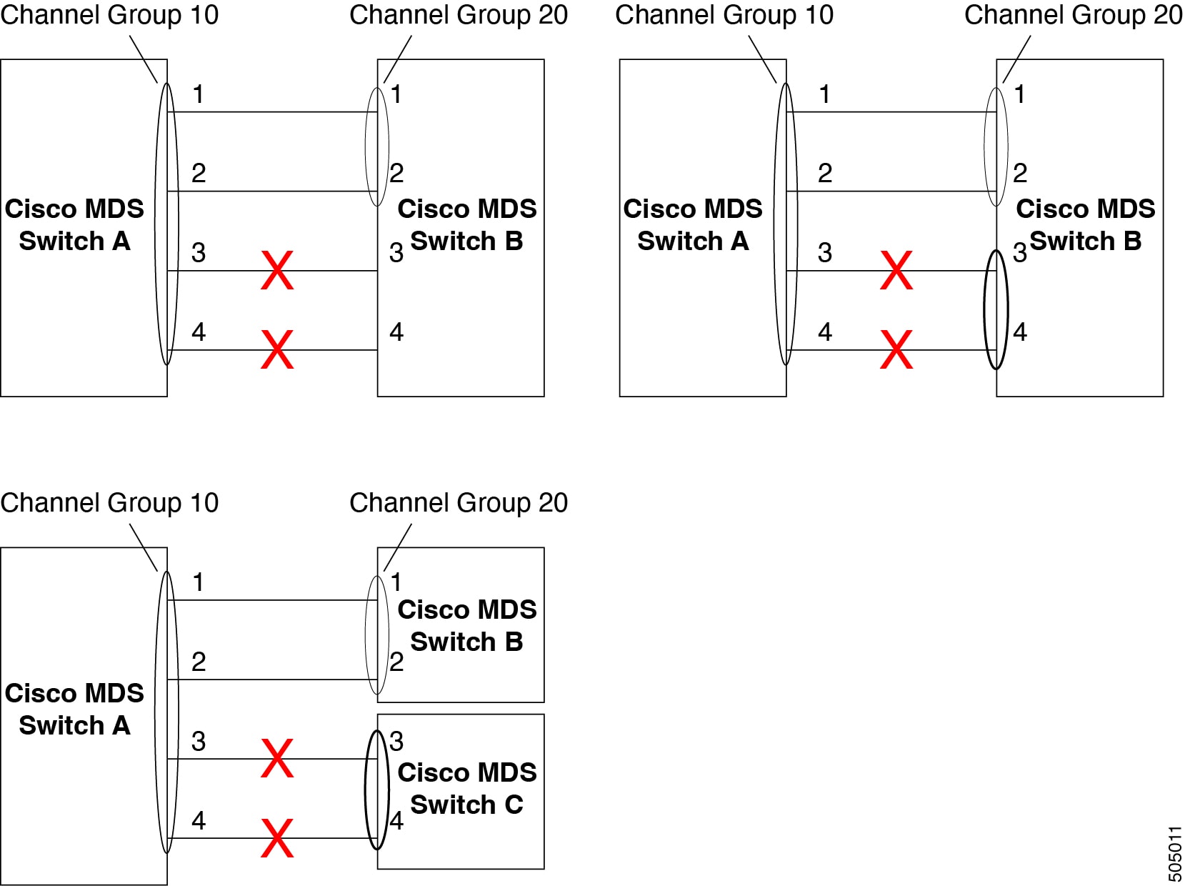
The following figure provides examples of invalid configurations. Assuming that the links are brought up in the 1, 2, 3, 4 sequence, links 3 and 4 will be operationally down as the fabric is misconfigured.
Default Settings
The following table lists the default settings for Port Channels.
| Parameters | Default |
|---|---|
|
Port Channels |
FSPF is enabled by default. |
|
Create Port Channel |
Administratively up. |
|
Default Port Channel mode |
ON mode on non-NPV and NPIV core switches.ACTIVE mode on NPV switches. |
|
Autocreation |
Disabled. |
Create Port Channel Wizard
To create a Port Channel using the Create New Port Channel Wizard on the Nexus Dashboard Fabric Controller Web UI, perform the following steps:
-
Choose Create a new Port Channel from the Actions drop-down list.
Click Create New Port Channel to launch the Create Port Channel Wizard.
-
In the Select Switch Pair screen, perform the following steps:
-
Select the appropriate fabric from the Fabric drop-down.
The list contains switch pairs in the fabric that have an ISL between them, that is not already in a port channel.
-
Select a switch pair to be linked by an FC Port Channel.
If there are NPV links between NPIV-core and NPV switches, you must enable F Port Trunking and Channeling Protocol using the feature fport-channel-trunk command on the NPIV switch in order to see the switch-pair and the number of NPV links.
-
Click Next.
-
-
In the Select ISLs screen, select one or more ISLs or Links to create a new Channel between the switch pair.
-
From the list of ISLs in the Available area, select and click right arrow to move the ISL to the Selected area.
-
Click Next.
-
-
In the Configure Channel screen, define, or edit the channel attributes.
-
Channel ID field is populated with the next unused channel ID. Change the channel ID or description for each switch, if necessary.
The range of the channel ID is from 1 to 256.
-
FICON Port Address is only enabled if the switches are FICON enabled. From the drop-down list, select the appropriate FICON port address on the switch. Select the port address that you want to assign to the Port Channel port.
-
In the Channel Attributes area, to configure the speed, click the appropriate radio button.
-
Select the appropriate Trunk Mode radio button to enable trunking on the links in the Port Channel.
-
Select trunk if your link is between TE ports.
-
Select nonTrunk if your link is between E ports.
-
Select auto if you are not sure.
-
-
In the Port VSAN field, enter the interface ID for port VSAN which must be used when trunking is not enabled.
Every interface must have a port VSAN even if trunking is enabled. If trunking is enabled, this port VSAN is not used. However, the switch must configure the port, so that the network knows what VSAN to use by default, if trunking is disabled.
-
VSAN list field provides a list of VSANs you want to allow the port channel to use for trunking.
This field is disabled if the Trunk Mode is set to nonTrunk or auto.
-
In the Core Switch Bandwidth field, select dedicated or shared radio button to allocate the switch bandwidth.
This bandwidth is applicable only for port channels between an NPIV and NPV switch.
-
Check the Force Admin, Trunk, Speed, and VSAN attributes to be identical check box to ensure that the same parameter settings are used in all physical ports in the channel. If these settings are not identical, the ports cannot become part of the Port Channel.
-
-
Click Previous to return to the previous screen and edit the settings. Click Create new port channel to configure the Port Channel.
A success message appears.
Edit Existing Port Channel
To edit a Port Channel using the Edit Port Channel Wizard on the Nexus Dashboard Fabric Controller Web UI, follow these steps:
-
Choose Edit Port Channel from the Actions drop-down list.
Click Edit Port Channel to launch the Create Port Channel Wizard.
-
In the Select Switch Pair screen, do the following:
-
Select the appropriate fabric from the Fabric drop-down list.
The switch pairs that have port channels between them are listed in the area below.
-
Select a switch pair to edit the port channel.
-
Click Next.
-
-
In the Select Port Channel screen, choose a Port Channel to edit.
Click Next.
-
In the Edit Port Channel screen, select the desired ISL.
-
Click the right and left arrow to select the available ISLs.
The selected ISLs are contained in the Port Channel after you save the changes. If the Selected ISLs list is empty, the Delete Port Channel is Empty check box is enabled.
-
If you do not choose any ISL, check the Delete Port Channel if Empty check box to delete the port channel.
-
Check the Force admin, trunk, speed, VSAN attributes to be identical check box to choose identical values for admin, trunk, speed and VSAN attributes.
-
Click Next.
-
-
Click Save port channel to apply the changes.
NPV Links
To view NPV (N_Port Virtualization) and NPIV (N_Port ID Virtualization) links in your system, navigate to the SAN Links page:
SAN > Links
then click the NPV Links tab. The configured NPV links are displayed.
The table shows the performance of NPV links on SAN Fabrics. You can use the Show last day drop-down to filter the view by Day (24 hours), Week, Month, and Year.
Click the chart icon in the Name column to see a list of the traffic for the past 24 hours.
There are variations to this procedure. In addition to these basic steps, you can also perform the following steps to view detailed information for NPV links:
-
You can change the time range for this information by selecting from the drop-down list in the upper-right corner.
-
To view the detailed information for a specific period, drag the slider control to choose the time interval for which you need the information.
-
Use the chart icons to view the traffic chart in varied views. You can also use the icons to Append, Predict, and Interpolate Data.
-
To export the data into a spreadsheet, click the Export icon in the upper-right corner and click Save.
-
To view real-time information, choose Real Time from the drop-down list in the Chart menu.
Configuring NPV Links
Beginning with NDFC release 12.1.3, a new NPV configuration wizard is available.
The NPV configuration wizard only displays and allows for the selection of NPV devices that are already NPV enabled; NPV-disabled switches are not shown in the NPV configuration wizard.
To enable NPV on a switch, navigate to:
SAN > Switches
and double-click on the switch that you want to enable NPV on. Click on Enabled features, then click the toggle switch next to npiv to enable NPV on this switch.
You can now use the NPV configuration wizard once you have enabled the feature npiv on the appropriate switches.
To configure NPV links using the new NPV configuration wizard:
-
Navigate to the NPV Links page:
SAN > Links
then click the NPV Links tab.
-
Click Actions > Configure NPV.
The Configure NPV configuration wizard appears, with Step 1. Select NPV Devices selected.
-
In the Select a fabric field, choose a fabric from the drop-down menu.
The NPV devices in that fabric appear in the table.
-
In the table, select one or more NPV devices or NPV enabled switches to pair, then click Next.
The NPV configuration wizard moves to Step 2. Select NPV Core Switches.
-
Select one or more NPIV core or NPIV capable switches from the table, if necessary.
NPIV capable switches can be configured as NPIV cores.
The NPV configuration wizard automatically selects NPIV devices that are detected as being connected to the selected NPV devices. You can modify the automatically selected devices to select as many devices as you would like to pair.
-
Click Next.
The NPV configuration wizard moves to Step 3. NPV Device/NPIV Core Switch Pairs.
-
Create an NPV pair.
The Step 3. NPV Device/NPIV Core Switch Pairs part of the NPV configuration wizard displays the devices selected from the previous two steps in the process.
-
To automatically pair the connected switches, click Add All Connected Pairs.
-
To manually create an NPV pair, select an NPV device from the left table and an NPIV core switch from the right table, then click Add Selected Pair.
The added NPV pair is displayed in the table at the bottom of the page. To remove one or more pairs from the table at the bottom of the page, click Remove All Pairs.
-
-
Click Next.
The NPV configuration wizard moves to Step 4. Configure NPV associated ports.
-
Configure the NPV-associated ports between each NPV pair.
Choose the way that you want to configure the NPV-associated ports between each NPV pair:
-
Automatic: Choose this option to have NDFC automatically select the NP ports and their associated F ports based on the number of NP links between each NPV device and NPIV core pair. The NP ports are chosen from potential ports not connected to end devices.
If you choose the automatic option, you must also choose how many connections you would like (the number of NP links per NPV device and NPIV core pair). You will make that choice in the drop-down menu below the Automatic option box.
-
If there are enough ports based on your selection, then they are automatically paired and you are able to move to the next step in the process when you click Next.
-
If there are not enough ports based on your selection, then you can use the Manual option (described below) to configure the NPV-associated ports between each NPV pair.
-
-
Manual: Choose this option to manually select ports from the NPV devices and NPIV core switches to create pairs. Note that ports might not be listed if there are no configurable ports.
-
Select an NPV switch from the drop-down menu.
The tables below the drop-down menu are then populated with the appropriate ports for that device and the NPIV devices it is to be paired with.
-
Select an NPV device and port from the left table, and an NPIV core switch and port from the right table to make a pair.
-
Click Add Selected Pair.
The pair is displayed in the table at the bottom of the page.
-
-
-
Click Next.
The NPV configuration wizard moves to Step 5. Select VSAN.
-
Choose a VSAN for all NPV associated switches and ports.
-
Click Select Existing VSAN to choose an existing VSAN from a list of available VSANs, or
-
Click Input New VSAN ID to manually enter a VSAN ID. The VSAN ID must be a numeric value between 1 - 4093.
If you enter a VSAN ID that is already in use, a message appears, asking if you would like to use the first available match from the existing VSAN list instead or if you would like to try to manually input a new VSAN ID again.
-
Click Confirm to use the first available match from the existing VSAN list instead, or
-
Click Cancel to return to the Select VSAN screen so that you can try to manually input a new VSAN ID again.
-
-
-
Click Next.
The NPV configuration wizard moves to Step 6. Complete NPV Setup.
-
Review your configuration choices.
-
Click the Switch Actions tab to see what steps will be taken on each device.
-
Click the NPV Port Pairs tab to see a table listing the ports that are to be physically connected. This is the same information that was available at the bottom of Step 4 if you clicked on the Manual tab in that step.
-
-
Click Finish to apply the changes.
If you have the Switch Actions tab selected, you can see the progress of the actions from the Action column in real time. Click the entry in the Status column to bring up a sidebar with more details.
-
Physically connect each pair of NP and F ports.
Copyright
THE SPECIFICATIONS AND INFORMATION REGARDING THE PRODUCTS IN THIS MANUAL ARE SUBJECT TO CHANGE WITHOUT NOTICE. ALL STATEMENTS, INFORMATION, AND RECOMMENDATIONS IN THIS MANUAL ARE BELIEVED TO BE ACCURATE BUT ARE PRESENTED WITHOUT WARRANTY OF ANY KIND, EXPRESS OR IMPLIED. USERS MUST TAKE FULL RESPONSIBILITY FOR THEIR APPLICATION OF ANY PRODUCTS.
THE SOFTWARE LICENSE AND LIMITED WARRANTY FOR THE ACCOMPANYING PRODUCT ARE SET FORTH IN THE INFORMATION PACKET THAT SHIPPED WITH THE PRODUCT AND ARE INCORPORATED HEREIN BY THIS REFERENCE. IF YOU ARE UNABLE TO LOCATE THE SOFTWARE LICENSE OR LIMITED WARRANTY, CONTACT YOUR CISCO REPRESENTATIVE FOR A COPY.
The Cisco implementation of TCP header compression is an adaptation of a program developed by the University of California, Berkeley (UCB) as part of UCB’s public domain version of the UNIX operating system. All rights reserved. Copyright © 1981, Regents of the University of California.
NOTWITHSTANDING ANY OTHER WARRANTY HEREIN, ALL DOCUMENT FILES AND SOFTWARE OF THESE SUPPLIERS ARE PROVIDED “AS IS" WITH ALL FAULTS. CISCO AND THE ABOVE-NAMED SUPPLIERS DISCLAIM ALL WARRANTIES, EXPRESSED OR IMPLIED, INCLUDING, WITHOUT LIMITATION, THOSE OF MERCHANTABILITY, FITNESS FOR A PARTICULAR PURPOSE AND NONINFRINGEMENT OR ARISING FROM A COURSE OF DEALING, USAGE, OR TRADE PRACTICE.
IN NO EVENT SHALL CISCO OR ITS SUPPLIERS BE LIABLE FOR ANY INDIRECT, SPECIAL, CONSEQUENTIAL, OR INCIDENTAL DAMAGES, INCLUDING, WITHOUT LIMITATION, LOST PROFITS OR LOSS OR DAMAGE TO DATA ARISING OUT OF THE USE OR INABILITY TO USE THIS MANUAL, EVEN IF CISCO OR ITS SUPPLIERS HAVE BEEN ADVISED OF THE POSSIBILITY OF SUCH DAMAGES.
Any Internet Protocol (IP) addresses and phone numbers used in this document are not intended to be actual addresses and phone numbers. Any examples, command display output, network topology diagrams, and other figures included in the document are shown for illustrative purposes only. Any use of actual IP addresses or phone numbers in illustrative content is unintentional and coincidental.
The documentation set for this product strives to use bias-free language. For the purposes of this documentation set, bias-free is defined as language that does not imply discrimination based on age, disability, gender, racial identity, ethnic identity, sexual orientation, socioeconomic status, and intersectionality. Exceptions may be present in the documentation due to language that is hardcoded in the user interfaces of the product software, language used based on RFP documentation, or language that is used by a referenced third-party product.
Cisco and the Cisco logo are trademarks or registered trademarks of Cisco and/or its affiliates in the U.S. and other countries. To view a list of Cisco trademarks, go to this URL: http://www.cisco.com/go/trademarks. Third-party trademarks mentioned are the property of their respective owners. The use of the word partner does not imply a partnership relationship between Cisco and any other company. (1110R)
© 2017-2024 Cisco Systems, Inc. All rights reserved.