New and Changed Information
The following table provides an overview of the significant changes up to this current release. The table does not provide an exhaustive list of all changes or of the new features up to this release.
| Release Version | Feature | Description |
|---|---|---|
|
NDFC 12.2.2 |
Updated Layer 4 to Layer 7 use cases |
As part of the enhanced workflow for configuring Layer 4 to Layer 7 services (described in Layer 4 to Layer 7 Services Configuration), several new Layer 4 to Layer 7 use cases are provided in this article. |
NDFC Services Nomenclature and Redundancy Models
Before describing the various use cases that can be provisioned using NDFC 12.2.2, it is important to clarify the new NDFC nomenclature used for the provisioning of such use cases and also what are the services redundancy models that are supported.
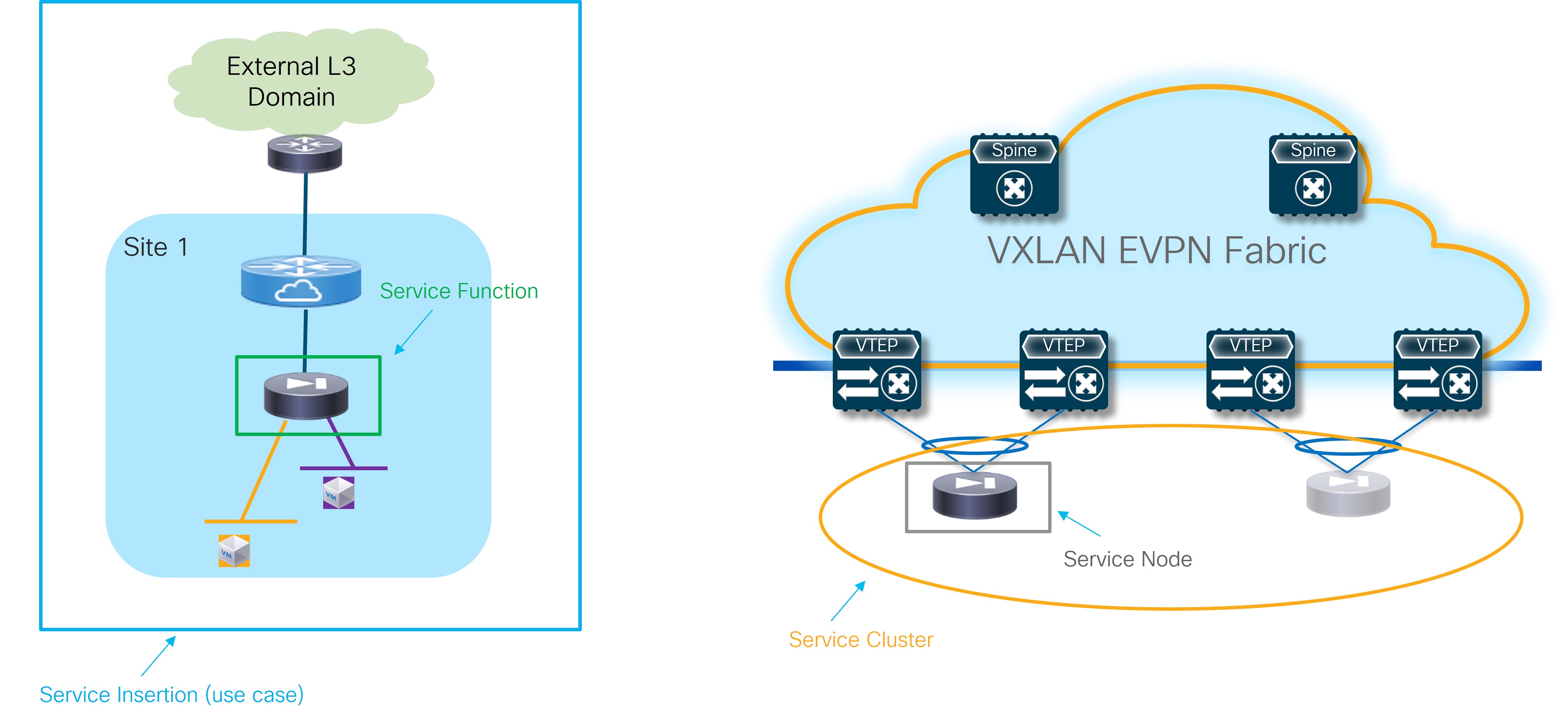
The figures below highlights the different building blocks required to provision L4/L7 service use cases with NDFC 12.2.2.

-
Service Insertion: Represents the set of use cases that are supported. The selection of a Service Insertion use case should always represent the first step of the workflow required to provision L4/L7 service insertion with NDFC 12.2.2. This is because it is the attachment (or detachment) of each given Service Insertion use case that drives the provisioning (or removal) of configurations on the fabric nodes.
-
Service Function: Identifies the specific L4/L7 service that should be integrated in the network (Firewall, Load-balancer, etc.). Depending on the selected Service Insertion use cases, a single service function or a chain of service functions will need to be provisioned as part of the workflow.
-
Service Cluster: Represents how the selected service function is going to be deployed, or more specifically, its redundancy model. These options are supported:
-
Active/Standby cluster: A pair of devices implementing a service function exposing a single MAC and IP address to the rest of the infrastructure. The specific MAC/IP is always owned by the Active device and inherited by the Standby when it gets activated as a result of a failover event.
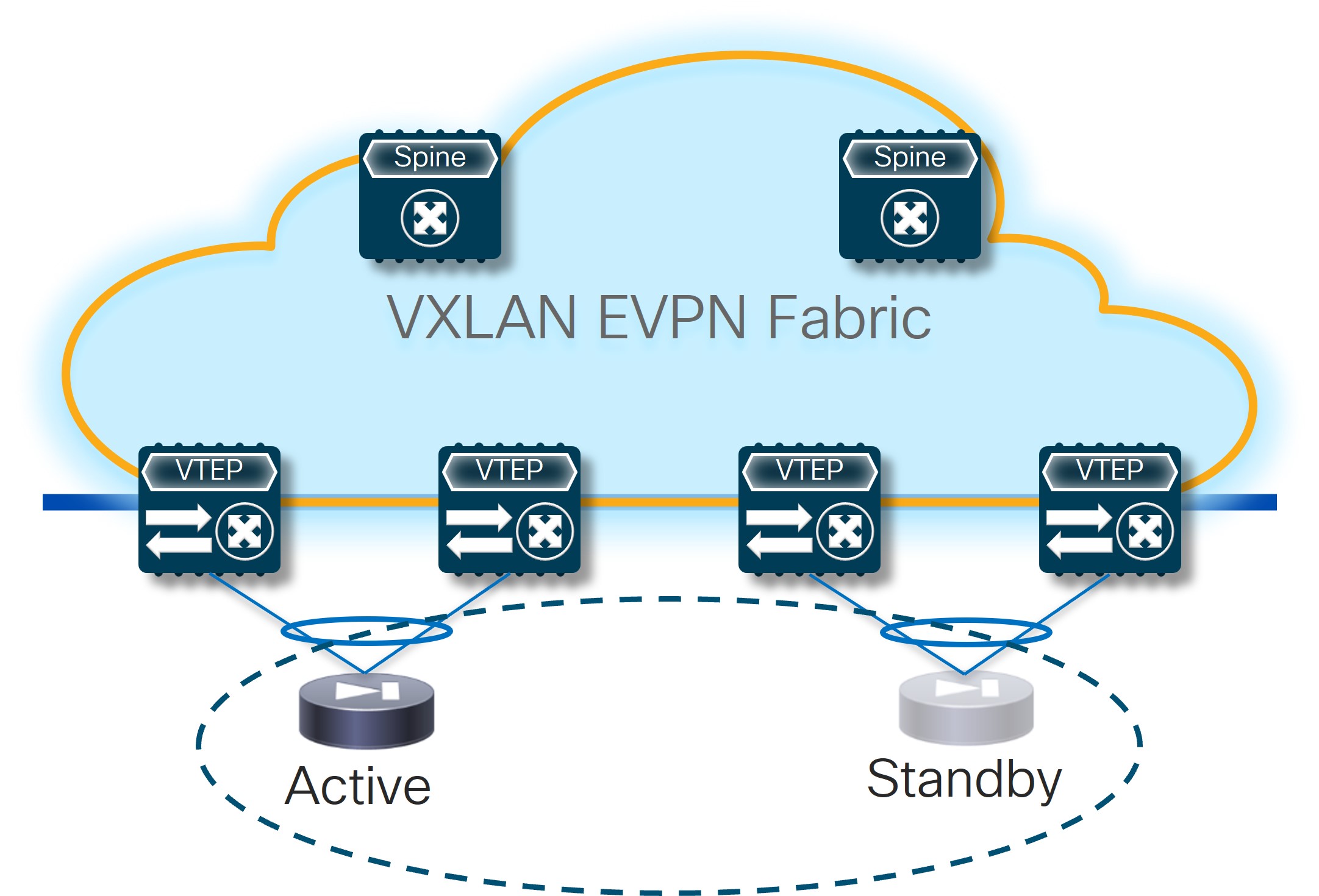 Active/Standby Cluster
 -
Active/Active cluster: Multiple devices (the maximum number depends on the specific cluster implementation) clustered together and working in active/active mode while still being seen as a single MAC/IP combo by the network infrastructure (in other words, all the active nodes in the cluster own the same MAC/IP addresses pair).
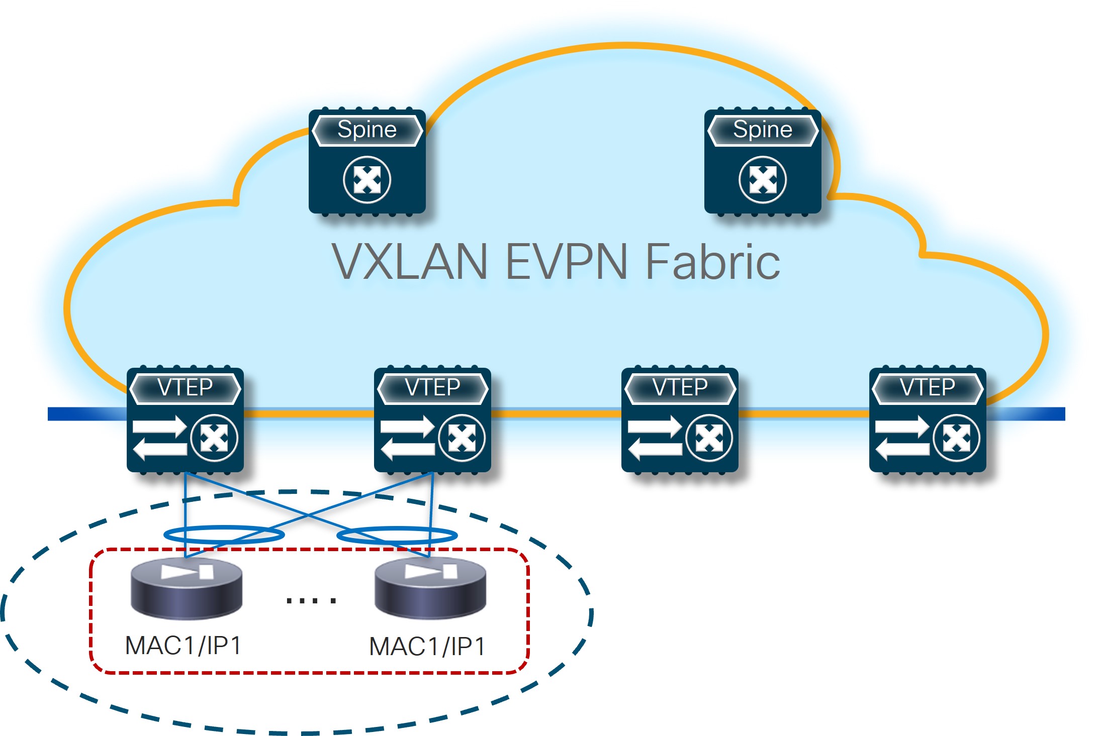 Active/Active Cluster
 -
Standalone nodes: This is a specific type of “cluster” built with a set of standalone service nodes, each of them owning a dedicated MAC/IP addresses pair. The deployment of a service function with a set of MAC/IP addresses pairs implies that a mechanism is required to ensure the traffic can be load-balanced across them without creating any asymmetricity in the traffic path (since the standalone nodes usually do not synchronize connection state between them).
Since a “standalone” node is identified by a single MAC/IP pair, it could also be implemented with an Active/Standby or an Active/Active cluster.
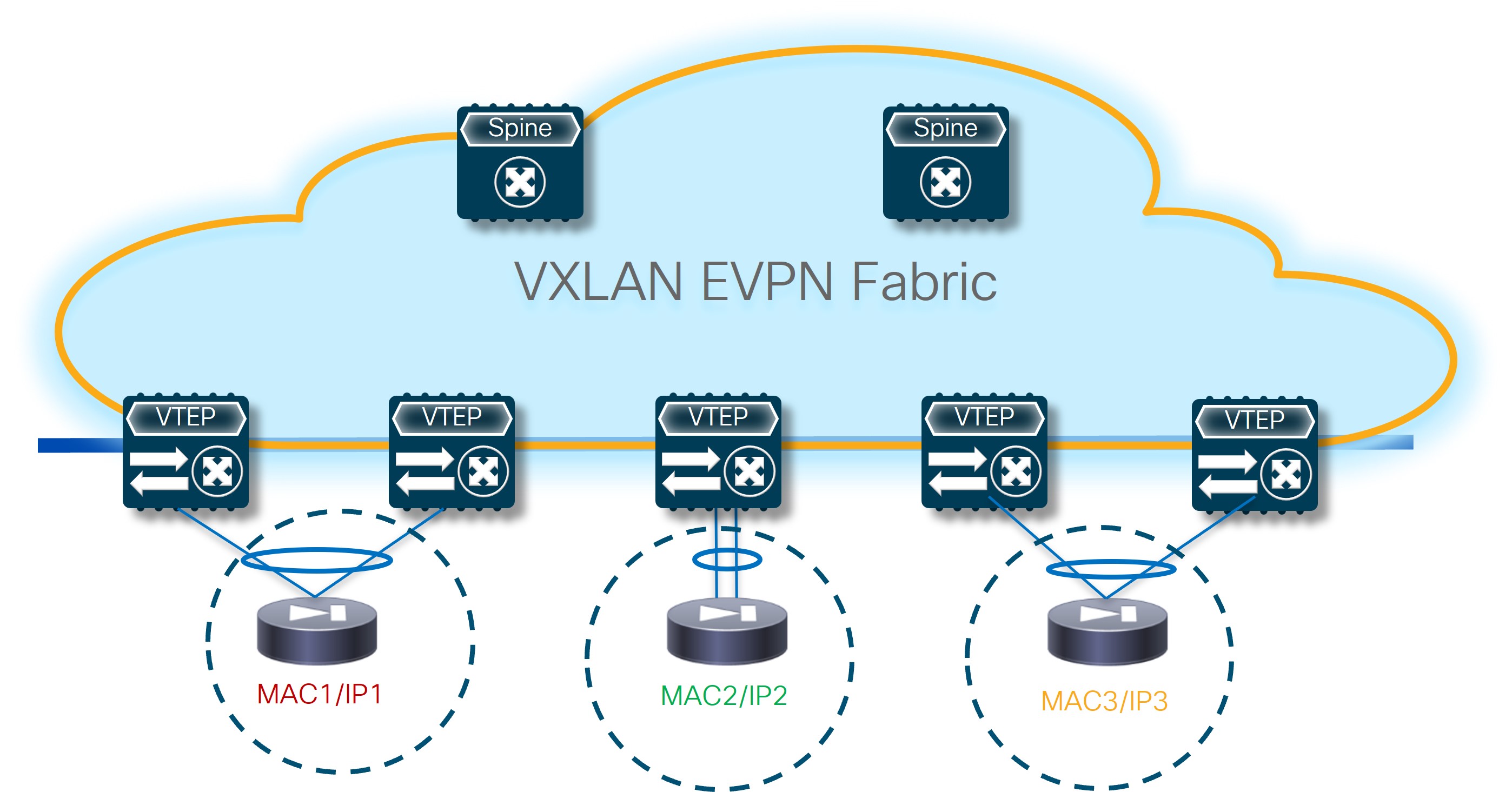 Standalone Service Nodes
-
-
Service Node: Represents the specific device providing the service function duties. Those devices come in different form factors (physical or virtual).
The following sections describe in detail various L4/L7 service insertion use cases in a VXLAN EVPN fabric, highlighting the various configuration steps that are required. While NDFC provides flexibility on how to provision those use cases, we strongly recommend that you follow the workflows described in this configuration guide.
In previous NDFC releases, the attach/detach option was also associated directly to the service function and there was no concept of a “Service Insertion” use case. When upgrading from an older release to NDFC 12.2.2 (which is part of the ND 3.2.1 unified image, the older configuration will be honored (there is no disruption caused to the traffic and to the configuration already provisioned to the fabric).
However, the pre-12.2.2 configuration won’t be converted into a specific Service Insertion use case, which essentially means it won’t be possible to remove or modify that configuration.
Use Case 1: Service Function as Default Gateway
Refer to the figure below for a logical view of the Service Function as Default Gateway use case. While firewall and load-balancer functions are shown in the figure, the use case can apply to any generic service function.
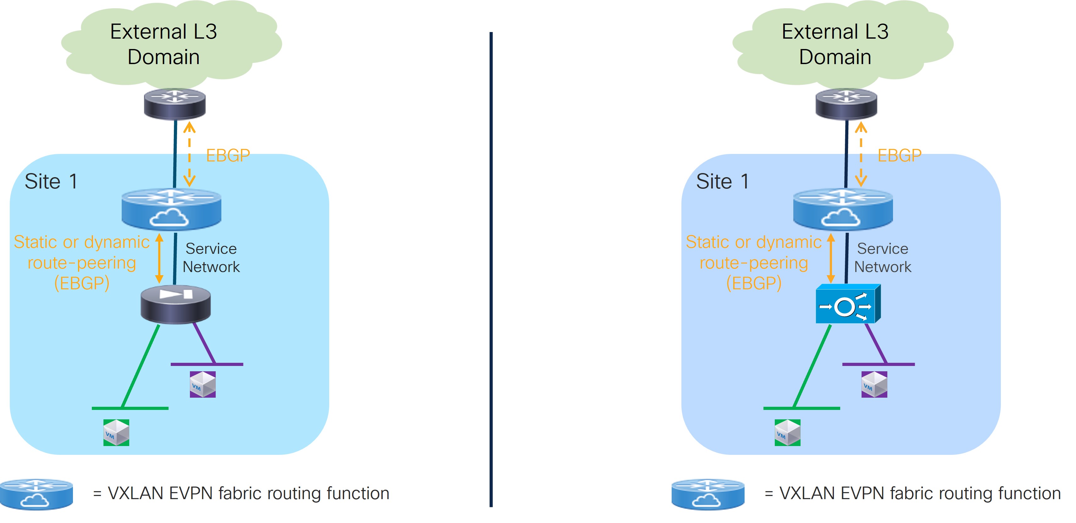
The service function is deployed in N arms mode:
-
The first arm allows for peering with a dedicated VRF deployed on the fabric. This peering can leverage static routing or the use of eBGP as control-plane. The fabric is usually peering in that VRF with the service function and with the external network domain to provide access to the data center resources connected behind the service function.
-
The other arms are connected to Layer 2 only networks deployed in the fabric and hosting the endpoints that use the service function as the default gateway.
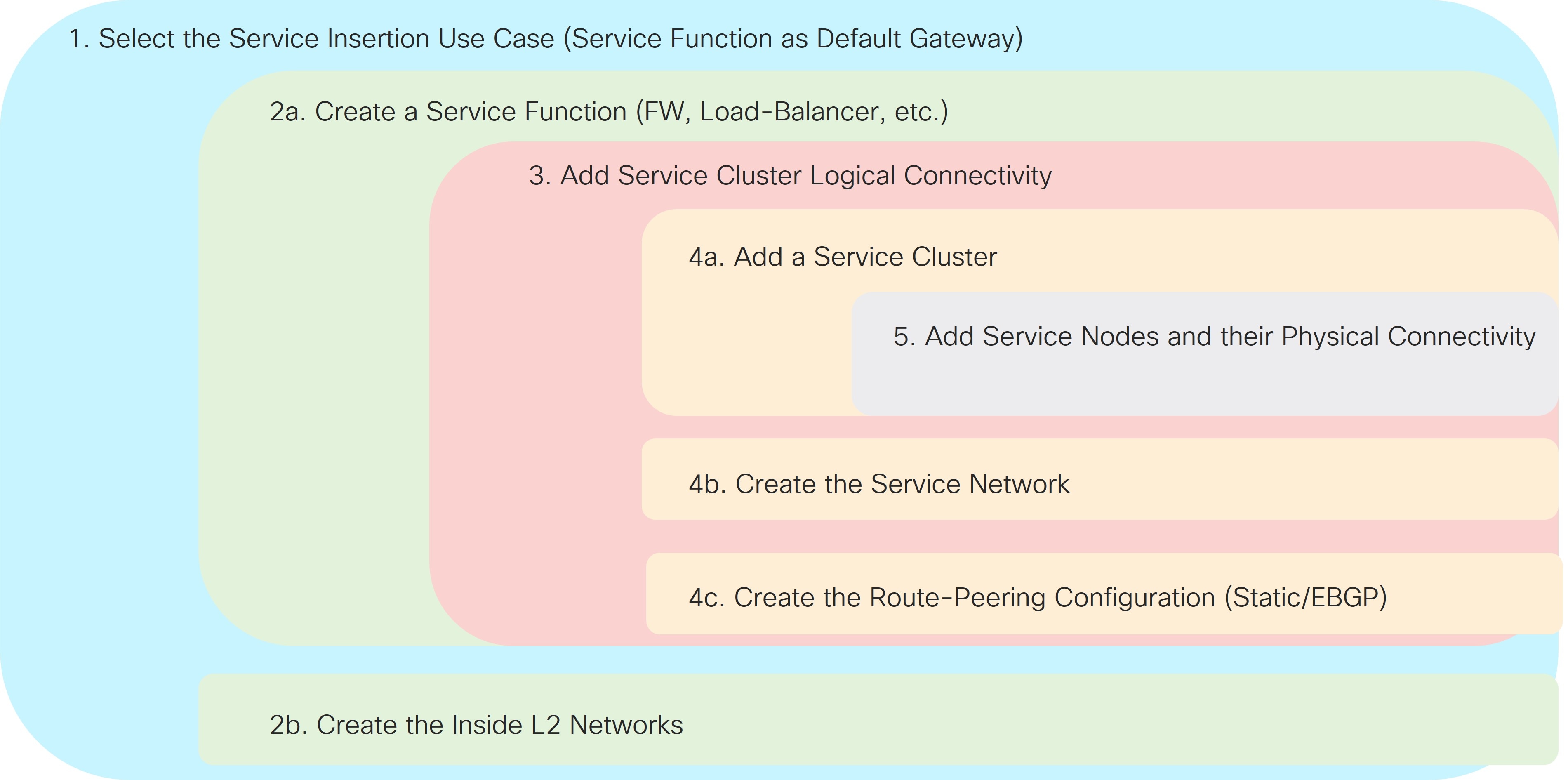
Refer to the figure below for a graphical representation of the NDFC workflow when configuring the Service Function as Default Gateway use case.
The provisioning steps shown in the figure below are going to be described in detail in the following sections. The number associated to each section matches the corresponding step in the diagram. Since the workflow moves back and forth between those steps, the numbering of the sections does not necessarily follow an ordered sequence.
1. Select the Service Insertion Use Case (Service Function as Default Gateway)
-
Navigate to the Service Insertions tab.
-
Navigate to:
Manage > Fabrics
-
Double-click the appropriate Data Center VXLAN EVPN fabric.
The Overview window for that fabric appears.
-
Click the Services tab.
-
Click the Service Insertions subtab.
A list of configured service insertion use cases is displayed.
-
-
Click Actions > Add Service Insertion.
The Add Service Insertion window is displayed.
-
Enter a name for the service insertion use case in the Service Insertion Name field.
The name can have alphanumeric, underscore, or dash characters. For example, for this particular use case, you might use
FW-as-Default-Gwyas the service insertion name. -
In the Use Case field, choose the appropriate use case.
For this use case, you will choose Service as Default Gateway as the use case.
-
In the Outside VRF Name field, choose the VRF in the fabric that the service function peers with.
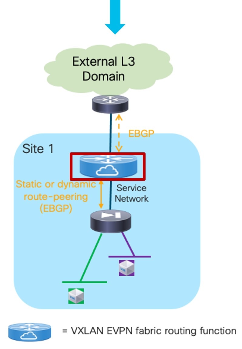 Service Function as Default Gateway: Outside VRF
Choose an existing outside VRF to associate with this service insertion use case, or click +Create VRF to create a new VRF. Refer to the section "VRFs" in About Fabric Overview for LAN Operational Mode Setups for more information.
-
In the Detach/Attach field, toggle the switch to detach or attach.
Selecting the Attach option is required to be able to provision the configuration to the switches at the end of the specific service insertion workflow. You can select the Attach option at this point or at the end of the procedures, after you have completed all the steps in the configuration workflow.
-
In the Service Function field, choose an existing service function to associate with this service insertion use case, or click +Create Service Function to create a new service function.
-
Clicking +Create Service Function to create a new service function is the recommended approach as it ensures that the proper options (one-arm, two-arms, and so on) for the service function are automatically proposed based on the specific service insertion use case that is being provisioned. If you click +Create Service Function, go to 2a. Add Service Function.
-
If you choose an existing, already-configured service function for this use case, because you chose Service as Default Gateway in the Use Case field, the service function pull-down list is pre-populated with service functions that have specific configuration options, such as N Arms connectivity mode and the outside VRF specified in step 5. Go to 2b. Create/Select the Inside Networks.
-
2a. Add Service Function
-
In the Type field, choose the type of service function to be deployed.
In our specific example, you will choose Firewall as the type of service function to be deployed.
-
In the Service Function Name field, enter a name for the service function.
The name can have alphanumeric, underscore, or dash characters.
-
Verify the information in the next two fields.
The next two fields are automatically populated based on information that you provided already:
-
Connectivity Mode: N Arms automatically selected based on the service insertion “Service as Default Gateway” use case that you chose in Step 1.
-
Outside VRF: Automatically populated based on the entry that you provided in the Outside VRF Name field in 1. Select the Service Insertion Use Case (Service Function as Default Gateway).
-
-
Click + Add Service Cluster Logical Connectivity.
This allows you to provision the service network used to peer the service node with the fabric’s VRF and the endpoints' Layer 2 networks leveraging the service node as the default gateway.
The Add Service Cluster Logical Connectivity window appears. Go to 3. Add Service Cluster Logical Connectivity.
3. Add Service Cluster Logical Connectivity
-
In the Service Cluster Name field, select an already-configured service cluster, or click +Add Service Cluster to create a new one.
-
If you clicked +Add Service Cluster, go to 4a. Add Service Cluster.
-
If you choose an existing, already-configured service cluster for this use case, go to 4b. Add Service Cluster Logical Connectivity.
-
4a. Add Service Cluster
-
Verify the information in the Type field.
The Type field is automatically populated based on the service insertion use case that you chose in Step 1 in 2a. Add Service Function.
-
Enter the necessary information to add a service cluster.
Field
Description
Service Cluster Name
Enter a name for the service cluster. The name can have alphanumeric, underscore, or dash characters.
Node Redundancy
Choose the node redundancy:
-
Standalone: Applicable if you are adding a single service node in the next step.
-
Active/Standby Cluster: Applicable if you are adding two service nodes in the next step, being part of the same Active/Standby cluster.
-
Active/Active Cluster: Applicable if you are adding two or more service nodes in the next step, being part of a single Active/Active cluster.
Form Factor
Select Physical or Virtual.
-
-
Click + Add Service Node.
The Add Service Node window appears. Go to 5. Add Service Nodes to define the service nodes part of the cluster and their physical connectivity to the fabric.
5. Add Service Nodes
For the specific example described here, you will be configuring the two service nodes (FW-Node1 and FW-Node2, as part of the same Active/Standby cluster) as shown in the figure below.
You can also deploy an Active/Active cluster as the default gateway, if desired.
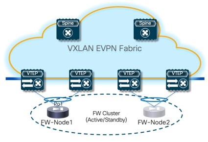
Connecting the service nodes part of the cluster to different sets of leaf nodes, as shown in the figure above, is recommended to increase the resiliency of the service function. However, NDFC 12.2.2 does not allow the provisioning of eBGP peering between the active firewall device and the remote VTEP nodes where the standby firewall device is connected when you choose the “Active/Standby” cluster option for the deployment of the firewall service function.
Establishing those eBGP adjacencies is usually recommended to minimize the traffic outage in a firewall failover scenario.
A possible workaround available with NDFC 12.2.2 consists in deploying the firewall service function as two “Standalone” clusters, with each node of the cluster connected to different VTEP nodes, as shown in Figure 9. In this case, it is possible to provision eBGP connectivity between each standalone firewall and the local VTEP nodes where it connects (each firewall node will specify a different pair of VTEP nodes). As a result, the active firewall node (the only one actively running the eBGP protocol) would establish eBGP adjacencies with both the local VTEP nodes and the remote VTEP nodes (where the standby firewall node is connected).
Following are additional alternative deployment options that are fully supported with NDFC 12.2.2 when deploying the firewall service function as an “Active/Standby” cluster:
-
Connect the firewall nodes to different VTEP nodes (as shown in Figure 9) and use static routing instead that eBGP between the firewall function and the fabric.
-
Connect both the active and standby firewall devices to the same pair of VTEP nodes. That way, the active firewall node (the only one actively running the eBGP protocol) would only have to peer with the VTEP nodes where it is locally connected.
-
Enter a name for the service node in the Service Node Name field.
For example,
FW-Node1. -
Click + Add Service Node Physical Connectivity to define how the node is physically connected to the fabric.
The Add Service Node Physical Connectivity window appears.
-
Enter the necessary information in the Add Service Node Connectivity window.
Field
Description
Service Node Name
Automatically populated with the service node name that you entered in the previous step.
Service Node Interface
Enter the service node interface. The service node interface is used for visualization and does not need to strictly match the name of any specific interface of the service node (even if it is operationally useful to do so).
Service Node Interface Usage
Choose the service node interface usage.
In the specific example shown in Figure 9, each service node is connected to a pair of service leaf nodes using a single vPC connection (different VLANs are trunked on that vPC to provide connectivity for the Service Network and the Inside Networks). Because of this, you will choose the Inside-Outside option for the Service Node Interface Usage. If separate physical interfaces are used instead for providing connectivity for the Service Network and the Inside Networks respectively, you will have to choose separate Inside and Outside Service Node Interfaces.
Attached Switch
Select a switch or a switch pair from the list, depending on whether the service node is single-attached or dual-attached.
Switch Interface
Select the interface from the list.
-
If you selected a vPC pair in the Attached Switch list, a list of vPC port-channels defined on those switches will be shown in the Switch Interface list.
-
Otherwise, the port-channel and interfaces configured in trunk mode are shown in the Switch Interface list.
Link Template
Select the service_link_trunk, service_link_port_channel_trunk, or the service_link_vpc template from the drop-down list based on the specified attached switch interface type. For more information on template fields, see the section "Templates" in Layer 4 to Layer 7 Services Configuration.
-
-
Click Save after you have entered the necessary information in the Add Service Node Physical Connectivity window.
You are returned to the Add Service Node window.
-
Repeat the previous steps to add another service node interface, or click Save in the Add Service Node window to save the service node information.
You are returned to the Add Service Cluster window.
-
Click + Add Service Node, then repeat the steps in this section to add the second service node for this use case (
FW-Node2).When you have completed the steps to add the
FW-Node2service node, you should see information forFW-Node1andFW-Node2in the Service Nodes area in the Add Service Cluster window. -
Click Save in the Add Service Cluster window to save the service cluster information.
You are returned to the Add Service Cluster Logical Connectivity page. Continue to 4b. Add Service Cluster Logical Connectivity to complete the service cluster logical connectivity configurations.
4b. Create the Service Network
At this point in these use case procedures, you have either selected an already-configured service cluster or you configured a new service cluster. Enter the necessary information to continue the process of adding service cluster logical connectivity. This entails choosing or creating the network used as the Service Network to peer the service function with the fabric’s VRF and the endpoints' Layer 2 networks.
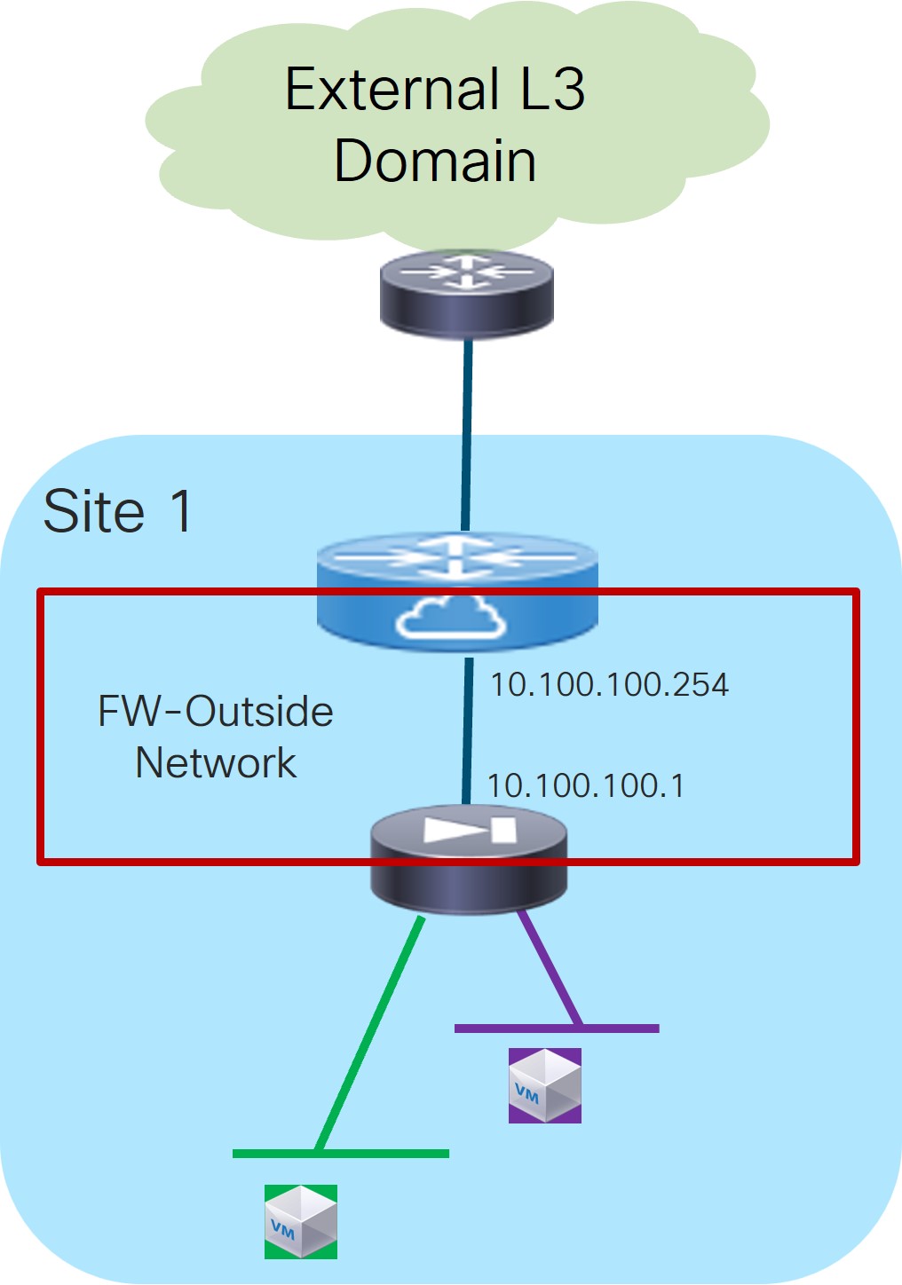
-
In the IPv4 and/or IPv6 field, choose from the following options:
-
IPv4
-
IPv6
-
IPv4 and IPv6
In our example, we will be choosing IPv4.
-
-
Enter the necessary information in this window to complete the configuration of the service cluster logical connectivity.
Normally, the remaining fields in this window vary depending on the connectivity mode that you chose. However, since you chose N Arms as the connectivity mode for this use case, the following fields appear:
Field
Description
Outside Service IPv4
Enter the firewall’s outside IPv4 and/or IPv6 service address. This is the IP address to which the service leaf node will establish L3 connectivity (either statically or via eBGP).
For example, for this use case’s example configuration figure shown at the beginning of this section, you would enter
10.100.100.1in this field.Outside Service IPv6
Outside Service Network
Choose an existing outside service network to associate with this service function, or click +Add Service Network to create a new service network. Refer to the section "Networks" in About Fabric Overview for LAN Operational Mode Setups for more information.
If you were creating a new service network, for this use case’s example configuration figure shown at the beginning of this section, you would enter
10.100.100.254/24in the IPv4 Anycast Gateway/Netmask field. This value would appear in the Gateway IP field in the Outside Service Network area in the Add Service Cluster Logical Connectivity window in this case.Probe
The use of probes is not required for a Service as Default Gateway use case.
Peering Option
Choose the appropriate peering option to define how to peer the firewall node to the fabric on the Service Network. Note that some peering options might not be available, depending on the previous configurations that you made.
-
Static
-
eBGP
-
Connected: You would normally select this peering option if you already have your routing in place; however, for this use case, you will configure either static or eBGP peering.
Peering Configuration
Choose the appropriate peering configuration to associate with this service function, or click +Add Peering Configuration to create a new peering configuration.
For this use case, continue to either of the following sections to configure either static or eBGP peering:
-
4c. Static Peering
-
In the Add Peering Configuration window, enter a name in the Peering Name field.
-
In the Peering Template field, choose
service_static_route(this option is pre-selected based on your choice of Static Peering in the Peering Configuration field in the previous section). -
Enter the necessary information to configure the static peering route.
Field
Description
Static Routes
Enter the static routes in the Static Routes field. You can enter one static route per line.
For example, if you were to enter the following value in the Static Routes field:
172.16.0.0/16, 10.100.100.1
-
172.16.0.0/16summarizes all the Layer 2 networks behind the firewall (using the firewall as the default gateway) -
10.100.100.1is the value that you entered earlier in these procedures for the firewall’s outside IPv4 service address
Export Gateway IP
Click to export the gateway IP (the service node IP) address as the next-hop address.
Enabling this option is required when the active and standby firewall nodes are connected to different leaf devices to ensure that traffic destined to the networks behind the firewall is always encapsulated toward the leaf nodes where the active firewall is connected. For more information about the use of Export Gateway IP when integrating service functions in a VXLAN EVPN fabric, see the Cisco VXLAN Multi-Site and Service Node Integration white paper.
-
-
Click Save after you have entered the necessary information in the Add Peering Configuration window.
You are returned to the Add Service Cluster Logical Connectivity window.
-
Click Save after you have entered the necessary information in the Add Service Cluster Logical Connectivity window.
You are returned to the Add Service Insertion window. Go to 2b. Create/Select the Inside Networks.
4c. eBGP Peering
-
In the Add Peering Configuration window, enter a name in the Peering Name field.
-
In the Peering Template field, choose
service_ebgp_route(this option is pre-selected based on your choice of eBGP Peering in the Peering Configuration field in the previous section). -
Enter the necessary information to configure the eBGP peering route.
Field
Description
General Parameters
Service Node ASN
Specify the BGP ASN for the service nodes.
Service Node IP Address
Specify the IPv4 address or address with netmask (for example, 1.2.3.4 or 1.2.3.1/24). An IPv4 or IPv6 address is mandatory. This field will be pre-populated with the IP address configured as part of Step 4b.
Use Auto-Created Per VRF Per VTEP Loopback
Check the box to use the automatically-created per VRF per VTEP loopback IP address. Only applicable when the Per VRF Per VTEP Loopback IPv4/IPv6 Auto-Provisioning option is enabled in the fabric setting.
Loopback IP
Specify the IPv4 address of the loopback on the switch. Loopback IPv4 or IPv6 address is mandatory.
Specifically for this use case, this is the service leaf switch’s IP address that the active firewall node is peering with.
vPC Peer’s Loopback IP
Specify the IPv4 address of the peer switch’s loopback. The switch with the smaller serial number will take this value. This is only required when the service node is physically connected to a pair of leaf nodes that are part of the same vPC domain.
Specifically for this use case, this is the IP address of the second service leaf switch the active firewall is peering with.
Export Gateway IP
Click to export the gateway IP (the service node IP) address as the next-hop address.
Specifically for this use case, this option is required when the active and standby firewall nodes are connected to different leaf devices to ensure that traffic destined to the networks behind the firewall is always encapsulated toward the leaf nodes where the active firewall is connected.
For more information on the use of Export Gateway IP when integrating service functions in a VXLAN EVPN fabric, see the Cisco VXLAN Multi-Site and Service Node Integration white paper.
Advanced
Service Node IPv6 Address
Specify the IPv6 address or address with prefix of the neighbor.
Loopback IPv6
Specify the IPv6 address of the loopback on the switch.
vPC Peer’s Loopback IPv6
Specify the IPv6 address of the peer switch’s loopback. The switch with the smaller serial number will take this value. This is only required when the service node is physically connected to a pair of leaf nodes that are part of the same vPC domain.
Route-Map TAG
Specify the route-map tag that is associated with the interface IP.
IPv4 Inbound Route-Map
Specify the IPv4 inbound route map. No route map is used if this field is left blank.
IPv4 Outbound Route-Map
Specify the IPv4 outbound route map. If this field is left blank, the system uses
EXTCON-RMAP-FILTER, orEXTCON-RMAP-FILTER-ALLOW-HOSTif the Advertise Host Routes option is enabled.IPv6 Inbound Route-Map
Specify the IPv6 inbound route map. No route map is used if this field is left blank.
IPv6 Outbound Route-Map
Specify the IPv6 outbound route map. If this field is left blank, the system uses
EXTCON-RMAP-FILTER-V6, orEXTCON-RMAP-FILTER-V6-ALLOW-HOSTif the Advertise Host Routes option is enabled.Interface Description
Enter a description for the interface.
Local ASN
Specify a local ASN to override the system ASN.
Advertise Host Routes
Select this option to enable advertisement of /32 and /128 routes to the edge routers.
Enable eBGP Password
Select this option to enable the eBGP password.
Enabling this option automatically enables the following Inherit eBGP Password from Fabric Settings field.
Inherit eBGP Password from Fabric Settings
Select this option to inherit the eBGP password from the Fabric Settings.
Enabling this option automatically disables the following eBGP Password and eBGP Authentication Key Encryption Type fields.
eBGP Password
Enabled if you did not enable the Inherit eBGP Password from Fabric Settings field above.
If enabled, enter the encrypted eBGP Password hex string.
eBGP Authentication Key Encryption Type
Enabled if you did not enable the Inherit eBGP Password from Fabric Settings field above.
If enabled, enter the BGP key encryption type:
-
3: 3DES
-
7: Cisco
Enable Interface
Clear this option to disable the interface. By default, the interface is enabled.
vPC
Peering via vPC Peer-Link
Check this box to configure per-VRF peering through the vPC peer-link.
In this specific use case, if the service node is dual-attached in vPC mode to the leaf nodes, you must enable this Peering via vPC Peer-Link option unless you enabled the vPC advertise-pip option at the fabric level.
The remaining fields in this tab become available only if you enable the Peering via vPC Peer-Link option.
Source IP Address/Netmask
Specify the source IP address and netmask. For example, 192.168.10.1/30.
Destination IP Address
Specify the destination (BGP neighbor) IP address. For example, 192.168.10.2. The switch with the smaller serial number will take this value.
Source IPv6 Address/Prefix
Specify the source IPv6 address and netmask. For example, 2001:db9::1/120.
Destination IPv6 Address
Specify the destination IPv6 address. For example, 2001:db9::10. The switch with the smaller serial number will take this value.
VLAN for Peering Between vPC Peers
Enter a value for the VLAN peering between vPCs (minimum: 2, maximum: 4094). If no value is specified in this field, the VLAN ID will be automatically assigned from the VLAN pool shown in the vPC Peer Link VLAN Range field on the vPC tab of fabric setting screen.
-
-
Click Save after you have entered the necessary information in the Add Peering Configuration window.
You are returned to the Add Service Cluster Logical Connectivity window.
-
Click Save after you have entered the necessary information in the Add Service Cluster Logical Connectivity window.
You are returned to the Add Service Insertion window. Go to 2b. Create/Select the Inside Networks
2b. Create/Select the Inside Networks
Continue with these procedures to create or select the inside Layer 2 networks. Endpoints connected to those networks are using the service function as the default gateway.
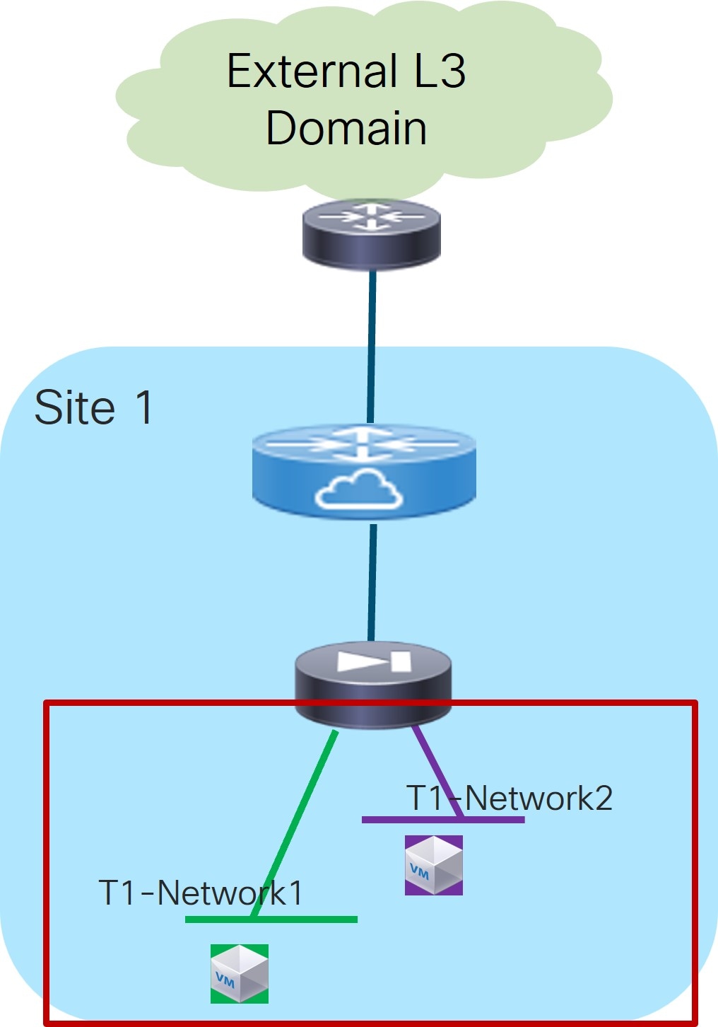
-
In the Inside L2 Network area, click + Add L2 Network, then choose an existing Layer 2 network to associate with this service insertion use case, or click +Create Network to create a new Layer 2 network. Refer to the section "Networks" in About Fabric Overview for LAN Operational Mode Setups for more information.
For this use case, the Layer 2 Only option is pre-selected because the service device is the default gateway.
-
When you have completed the configuration for inside Layer 2 network, click the check mark at the end of the row to accept the values that you entered.
Repeat these steps to configure additional inside Layer 2 networks, if necessary.
-
Click Save after you have entered the necessary information to add a service insertion with this use case.
You are returned to the Fabric Overview page, with Services > Service Insertions selected.
Attach and Deploy the Use Case
-
Check the box next to the new service insertion (if you haven’t done this previously) and click the lower (white) Actions dropdown, then select Attach.
After several seconds, the value shown in the Attached column changes to True.
-
Click the upper (blue) Actions dropdown, then select Recalculate and Deploy.
The new configurations are now deployed to the service leaf nodes.
Use Case 2: Service Function as Perimeter Device
Refer to the figure below for a logical view of the Service Function as Perimeter Device use case. While firewall and load-balancer functions are shown in the figure, this use case can apply to any generic service function.
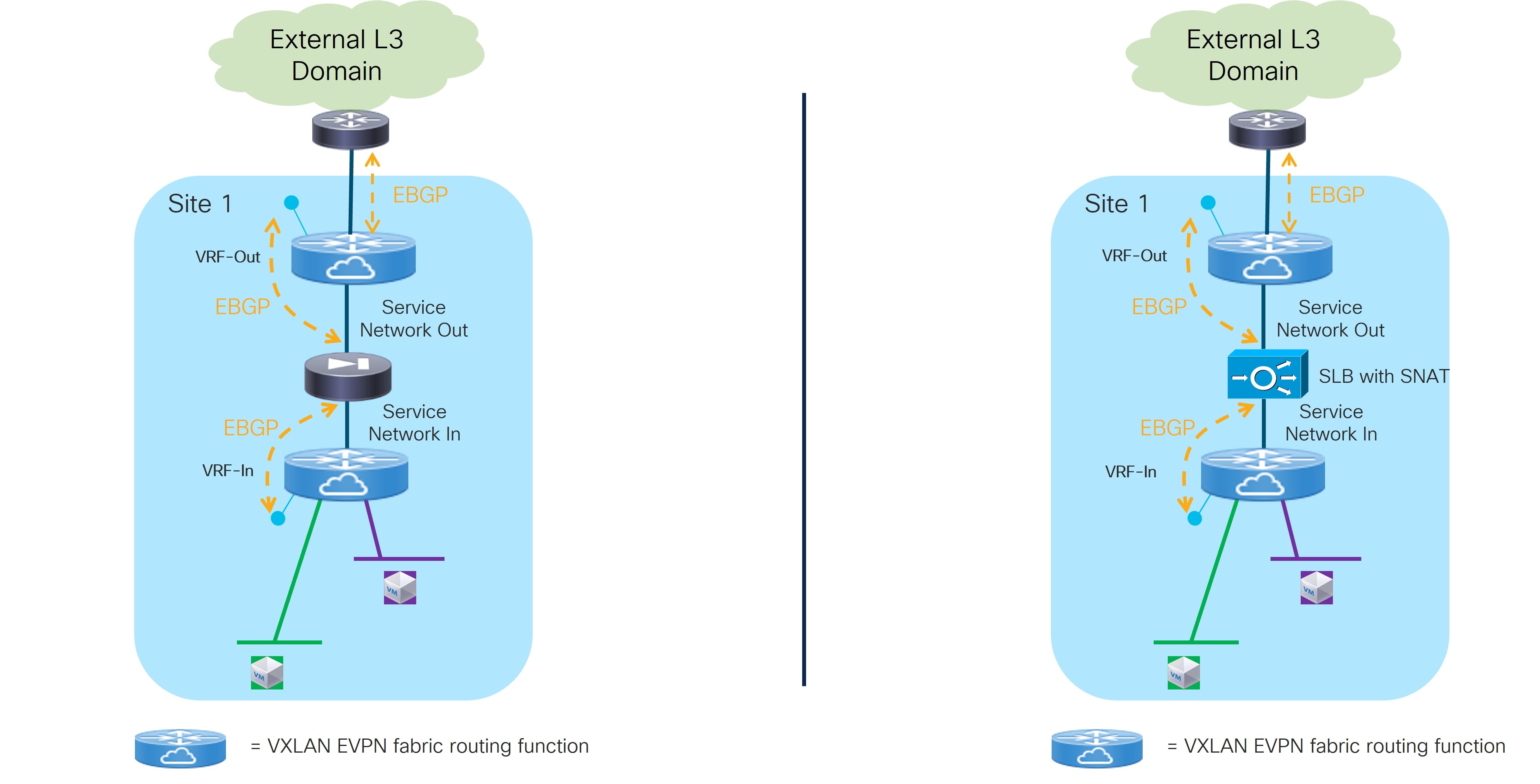
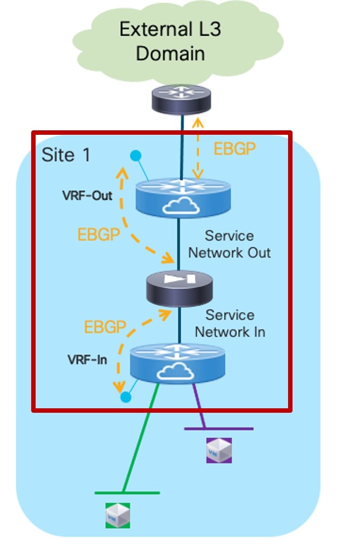
In this use case, the service function front-ends a specific “Inside VRF” deployed in the fabric. That way, all the traffic flows initiated from the endpoints part of this VRF and destined to endpoints in other VRFs or to the external Layer 3 network domain is steered through the service function, which can then perform its specific duties.
The service function is deployed in “two arms mode”:
-
The first arm allows for peering with the “Inside VRF” deployed in the fabric. This peering can leverage static routing or the use of EBGP as control-plane.
-
The second arm is instead used to peer with an “Outside VRF” also deployed in the fabric. Also in this case, the peering can leverage static routing or the use of EBGP as control-plane.
The specific Service Insertion use case described in this section forces the service function to peer southbound and northbound with two VRFs defined in the fabric. However, there are scenarios where the service function could peer northbound, directly or indirectly, with an external router, as described in the One Arm Perimeter Firewall section at the end of this document.
Refer to the figure below for a graphical representation of the workflow for configuring the Service Function as Perimeter Device use case.
The provisioning steps shown in the figure below are going to be described in detail in the following sections. The number associated to each section matches the corresponding step in the diagram. Since the workflow moves back and forth between those steps, the numbering of the sections does not necessarily follow an ordered sequence.
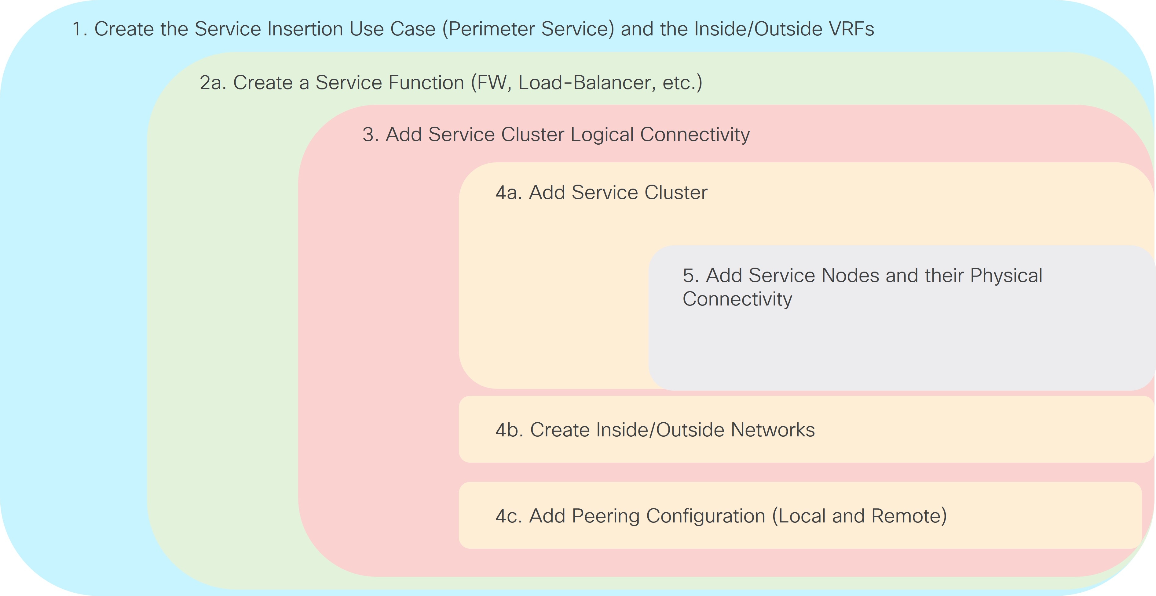
1. Select the Service Insertion Use Case (Perimeter Service)
-
Navigate to the Service Insertions tab.
-
Navigate to:
Manage > Fabrics
-
Double-click the appropriate Data Center VXLAN EVPN fabric.
The Overview window for that fabric appears.
-
Click the Services tab.
-
Click the Service Insertions subtab.
A list of configured service insertion use cases is displayed.
-
-
Click Actions > Add Service Insertion.
The Add Service Insertion window is displayed.
-
Enter a name for the service insertion use case in the Service Insertion Name field.
The name can have alphanumeric, underscore, or dash characters. For example, for this particular use case, you might use
FW-as-Perimeteras the service insertion name. -
In the Use Case field, choose the appropriate use case.
For this use case, you will choose Perimeter Service as the use case.
-
Choose or create an outside VRF and an inside VRF.
These are the VRFs in the fabric that the service function peers with.
 Service Function as Perimeter Device: Outside and Inside VRFs
-
In the Outside VRF Name field, choose an existing outside VRF to associate with this service insertion use case, or click +Create VRF to create a new VRF.
-
In the Inside VRF Name field, choose an existing inside VRF to associate with this service insertion use case, or click +Create VRF to create a new VRF.
Refer to the section "VRFs" in About Fabric Overview for LAN Operational Mode Setups for more information.
-
-
In the Detach/Attach field, toggle the switch to detach or attach.
Selecting the Attach option is required to be able to provision the configuration to the switches at the end of the specific service insertion workflow. You can select the Attach option at this point or at the end of the procedures, after you have completed all the steps in the configuration workflow.
-
In the Service Function field, choose an existing service function to associate with this service insertion use case, or click +Create Service Function to create a new service function.
-
Clicking +Create Service Function to create a new service function is the recommended approach as it ensures that the proper options (one-arm, two-arms, and so on) for the service function are automatically proposed based on the specific service insertion workflow that is being provisioned. If you click +Create Service Function, go to 2. Add Service Function.
-
If you choose an existing, already-configured service function for this use case, because you chose Perimeter Service in the Use Case field, the service function pull-down list is pre-populated with service functions that have specific configuration options, such as the outside and inside VRF specified in step 5. Go to 3. Add Service Cluster Logical Connectivity.
-
2. Add Service Function
-
In the Type field, choose the type of service function to be deployed.
For this use case, you will choose Firewall as the type of service function to be deployed.
-
In the Service Function Name field, enter a name for the service function.
The name can have alphanumeric, underscore, or dash characters.
-
Verify the information in the next two fields.
The next three fields are automatically populated based on information that you provided already:
-
Connectivity Mode: Two Arms automatically selected based on the service insertion use case that you chose in Step 1.
-
Outside VRF: Automatically populated based on the entry that you provided in the Outside VRF Name field in 1. Select the Service Insertion Use Case (Perimeter Service).
-
Inside VRF: Automatically populated based on the entry that you provided in the Inside VRF Name field in 1. Select the Service Insertion Use Case (Perimeter Service).
-
-
Click + Add Service Cluster Logical Connectivity.
The Add Service Cluster Logical Connectivity window appears. Go to 3. Add Service Cluster Logical Connectivity.
3. Add Service Cluster Logical Connectivity
-
In the Service Cluster Name field, select an already-configured service cluster, or click +Add Service Cluster to create a new one.
-
If you clicked +Add Service Cluster, go to 4a. Add Service Cluster.
-
If you choose an existing, already-configured service cluster for this use case, go to 4b. Create Inside/Outside Networks.
-
4a. Add Service Cluster
-
Verify the information in the Type field.
The Type field is automatically populated based on the service insertion use case that you chose in Step 1 in 2a. Add Service Function.
-
Enter the necessary information to add a service cluster.
Field
Description
Service Cluster Name
Enter a name for the service cluster. The name can have alphanumeric, underscore, or dash characters.
Node Redundancy
Choose the node redundancy:
-
Standalone: Applicable if you are adding a single service node in the next step.
-
Active/Standby Cluster: Applicable if you are adding two service nodes in the next step, being part of the same Active/Standby cluster.
-
Active/Active Cluster: Applicable if you are adding two or more service nodes in the next step, being part of a single Active/Active cluster.
Form Factor
Select Physical or Virtual.
-
-
Click + Add Service Node.
The Add Service Node window appears. Go to 5. Add Service Nodes to define the service nodes part of the cluster and their physical connectivity to the fabric.
5. Add Service Nodes
For the specific example described here, you will be configuring the two service nodes (FW-Node1 and FW-Node2, as part of the same Active/Standby cluster) as shown in the figure below.
You can also deploy an Active/Active cluster as a perimeter firewall, if desired.
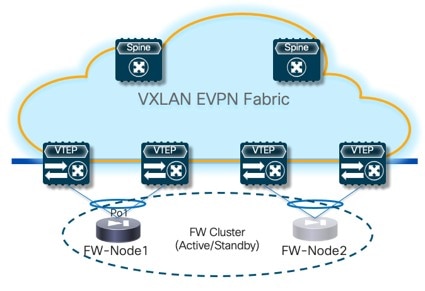
Connecting the service nodes part of the cluster to different sets of leaf nodes, as shown in the figure above, is recommended to increase the resiliency of the service function. However, NDFC 12.2.2 does not allow the provisioning of eBGP peering between the active firewall device and the remote VTEP nodes where the standby firewall device is connected when you choose the “Active/Standby” cluster option for the deployment of the firewall service function.
Establishing those eBGP adjacencies is usually recommended to minimize the traffic outage in a firewall failover scenario.
A possible workaround available with NDFC 12.2.2 consists in deploying the firewall service function as two “Standalone” clusters, with each node of the cluster connected to different VTEP nodes, as shown in Figure 12. In this case, it is possible to provision eBGP connectivity between each standalone firewall and the local VTEP nodes where it connects (each firewall node will specify a different pair of VTEP nodes). As a result, the active firewall node (the only one actively running the eBGP protocol) would establish eBGP adjacencies with both the local VTEP nodes and the remote VTEP nodes (where the standby firewall node is connected).
Following are additional alternative deployment options that are fully supported with NDFC 12.2.2 when deploying the firewall service function as an “Active/Standby” cluster:
-
Connect the firewall nodes to different VTEP nodes (as shown in Figure 12) and use static routing instead that eBGP between the firewall function and the fabric.
-
Connect both the active and standby firewall devices to the same pair of VTEP nodes. That way, the active firewall node (the only one actively running the eBGP protocol) would only have to peer with the VTEP nodes where it is locally connected.
-
Enter a name for the service node in the Service Node Name field.
For example,
FW-Node1. -
Click + Add Service Node Physical Connectivity to define how the node is physically connected to the fabric.
The Add Service Node Physical Connectivity window appears.
-
Enter the necessary information in the Add Service Node Connectivity window.
Field
Description
Service Node Name
Automatically populated with the service node name that you entered in the previous step.
Service Node Interface
Enter the service node interface. The service node interface is used for visualization and does not have to strictly match the name of any specific interface of the service node (even if it is operationally useful to do so).
Service Node Interface Usage
Choose the service node interface usage.
In the specific example shown in Figure 15, each service node is connected to a pair of service leaf nodes using a single vPC connection (different VLANs are trunked on that vPC to provide connectivity for the Outside Service Network and the Inside Service Network). Because of this, you will choose the Inside-Outside option for the Service Node Interface Usage. If separate physical interfaces are used instead for providing connectivity for the Outside Service Network and the Inside Service Network, you will have to choose separate Inside and Outside Service Node Interfaces.
Attached Switch
Select a switch or a switch pair from the list, depending on whether the service node is single-attached or dual-attached.
Switch Interface
Select the interface from the list.
-
If you selected a vPC pair in the Attached Switch list, a list of vPC port-channels defined on those switches will be shown in the Switch Interface list.
-
Otherwise, the port-channel and interfaces configured in trunk mode are shown in the Switch Interface list.
Link Template
Select the service_link_trunk, service_link_port_channel_trunk, or the service_link_vpc template from the drop-down list based on the specified attached switch interface type. For more information on template fields, see the section "Templates" in Layer 4 to Layer 7 Services Configuration.
-
-
Click Save after you have entered the necessary information in the Add Service Node Physical Connectivity window.
You are returned to the Add Service Node window.
-
Repeat the previous steps to add another service node interface, or click Save in the Add Service Node window to save the service node information.
You are returned to the Add Service Cluster window.
-
Click + Add Service Node, then repeat the steps in this section to add the second service node for this use case (
FW-Node2).When you have completed the steps to add the
FW-Node2service node, you should see information forFW-Node1andFW-Node2in the Service Nodes area in the Add Service Cluster window. -
Click Save in the Add Service Cluster window to save the service cluster information.
You are returned to the Add Service Cluster Logical Connectivity page. Continue to 4b. Create Inside/Outside Networks to complete the service cluster logical connectivity configurations.
4b. Create Inside/Outside Networks
At this point in these use case procedures, you have either selected an already-configured service cluster or you configured a new service cluster. Enter the necessary information to continue the process of adding service cluster logical connectivity. This entails choosing or creating the networks used to peer the service function with the fabric’s Inside and Outside VRFs.
-
In the IPv4 and/or IPv6 field, choose from the following options:
-
IPv4
-
IPv6
-
IPv4 and IPv6
In our example, we will be choosing IPv4.
-
-
Enter the necessary information in this window to complete the configuration of the service cluster logical connectivity.
Normally, the remaining fields in this window vary depending on the connectivity mode that you chose. However, since Two Arms was automatically selected based on the service insertion use case that you choose for this use case, the following fields appear:
Field
Description
Outside Service IPv4
Enter the firewall’s outside IPv4 and/or IPv6 service address. This is the IP address to which the service leaf node will establish L3 connectivity (either statically or via eBGP).
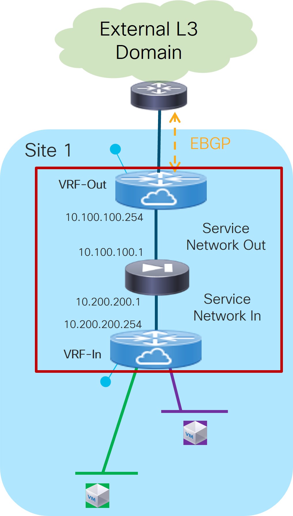
For example, for this use case’s example configuration figure shown at the beginning of this section, you would enter
10.100.100.1in this field.Outside Service IPv6
Outside Service Network
Choose an existing outside service network to associate with this service function, or click +Add Service Network to create a new service network. Refer to the section "Networks" in About Fabric Overview for LAN Operational Mode Setups for more information.
If you were creating a new service network, for this use case’s example configuration figure shown at the beginning of this section, you would enter
10.100.100.254/24in the IPv4 Anycast Gateway/Netmask field. This value would appear in the Gateway IP field in the Outside Service Network area in the Add Service Cluster Logical Connectivity window in this case.Peering Option
Choose the appropriate peering option to associate with this service function. Note that some peering options might not be available, depending on the previous configurations that you made.
-
Static
-
eBGP
-
Connected: You would normally select this peering option if you already have your routing in place; however, for this use case, you will configure either local or remote eBGP peering.
Peering Configuration
Choose the appropriate peering configuration to associate with this service function, or click +Add Peering Configuration to create a new peering configuration. See the section "Service Function Templates" in About Fabric Overview for LAN Operational Mode Setups for more information.
For this use case, we will choose eBGP for the peering configuration option. See 4c. Local eBGP Peering for more information.
Inside Service IPv4
Enter the firewall’s inside IPv4 and/or IPv6 service address.
For example, for this use case’s example configuration figure shown at the beginning of this section, you would enter
10.200.200.1in this field.Inside Service IPv6
Inside Service Network
Choose an existing inside service network to associate with this service function, or click +Add Service Network to create a new service network. Refer to the section "Networks" in About Fabric Overview for LAN Operational Mode Setups for more information.
If you were creating a new service network, for this use case’s example configuration figure shown at the beginning of this section, you would enter
10.200.200.254/24in the IPv4 Anycast Gateway/Netmask field. This value would appear in the Gateway IP field in the Inside Service Network area in the Add Service Cluster Logical Connectivity window in this case.Peering Option
Choose the appropriate peering option to associate with this service function. Note that some peering options might not be available, depending on the previous configurations that you made.
-
Static
-
eBGP
-
Connected: Select this peering option if you already have your routing in place. Intra-tenant firewall will only have Connected as the peering option.
Peering Configuration
Choose the appropriate peering configuration to associate with this service function, or click +Add Peering Configuration to create a new peering configuration. See the section "Service Function Templates" in About Fabric Overview for LAN Operational Mode Setups for more information.
For this use case, we will choose eBGP for the peering configuration option. Go to 4c. Local eBGP Peering.
-
4c. Local eBGP Peering
Use the information in this section to configure local eBGP peering for both the outside and inside networks in this use case.
-
In the Add Peering Configuration window, enter a name in the Peering Name field.
-
In the Peering Template field, choose
service_ebgp_route. -
Enter the necessary information to configure the eBGP peering route.
Since both the Inside and Outside VRFs are defined on the same fabric, they inherit the BGP ASN of the fabric by default. Therefore, to ensure a successful exchange of prefixes between them (through the firewall), we recommend that you use the “local-AS” configuration on each VRF to ensure that they all expose unique BGP ASNs. You can access this setting in the Advanced area.
Field
Description
General Parameters
Service Node ASN
Specify the BGP ASN for the service nodes.
Service Node IP Address
Specify the IPv4 address or address with netmask (for example, 1.2.3.4 or 1.2.3.1/24). An IPv4 or IPv6 address is mandatory. This field will be pre-populated with the IP address configured as part of Step 4b.
Use Auto-Created Per VRF Per VTEP Loopback
Check the box to use the automatically-created per VRF per VTEP loopback IP address. Only applicable when the Per VRF Per VTEP Loopback IPv4/IPv6 Auto-Provisioning option is enabled in the fabric setting.
Loopback IP
Specify the IPv4 address of the loopback on the switch. Loopback IPv4 or IPv6 address is mandatory.
Specifically for this use case, this is the service leaf switch’s IP address that the active firewall node is peering with.
vPC Peer’s Loopback IP
Specify the IPv4 address of the peer switch’s loopback. The switch with the smaller serial number will take this value. This is only required when the service node is physically connected to a pair of leaf nodes that are part of the same vPC domain.
Specifically for this use case, this is the IP address of the second service leaf switch the active firewall is peering with.
Export Gateway IP
Click to export the gateway IP (the service node IP) address as the next-hop address.
Specifically for this use case, this option is required when the active and standby firewall nodes are connected to different leaf devices to ensure that traffic destined to the networks behind the firewall is always encapsulated toward the leaf nodes where the active firewall is connected.
For more information on the use of Export Gateway IP when integrating service functions in a VXLAN EVPN fabric, see the Cisco VXLAN Multi-Site and Service Node Integration white paper.
Advanced
Service Node IPv6 Address
Specify the IPv6 address or address with prefix of the neighbor.
Loopback IPv6
Specify the IPv6 address of the loopback on the switch.
vPC Peer’s Loopback IPv6
Specify the IPv6 address of the peer switch’s loopback. The switch with the smaller serial number will take this value. This is only required when the service node is physically connected to a pair of leaf nodes that are part of the same vPC domain.
Route-Map TAG
Specify the route-map tag that is associated with the interface IP.
IPv4 Inbound Route-Map
Specify the IPv4 inbound route map. No route map is used if this field is left blank.
IPv4 Outbound Route-Map
Specify the IPv4 outbound route map. If this field is left blank, the system uses
EXTCON-RMAP-FILTER, orEXTCON-RMAP-FILTER-ALLOW-HOSTif the Advertise Host Routes option is enabled.IPv6 Inbound Route-Map
Specify the IPv6 inbound route map. No route map is used if this field is left blank.
IPv6 Outbound Route-Map
Specify the IPv6 outbound route map. If this field is left blank, the system uses
EXTCON-RMAP-FILTER-V6, orEXTCON-RMAP-FILTER-V6-ALLOW-HOSTif the Advertise Host Routes option is enabled.Interface Description
Enter a description for the interface.
Local ASN
Specify a local ASN to override the system ASN.
Advertise Host Routes
Select this option to enable advertisement of /32 and /128 routes to the edge routers.
Enable eBGP Password
Select this option to enable the eBGP password.
Enabling this option automatically enables the following Inherit eBGP Password from Fabric Settings field.
Inherit eBGP Password from Fabric Settings
Select this option to inherit the eBGP password from the Fabric Settings.
Enabling this option automatically disables the following eBGP Password and eBGP Authentication Key Encryption Type fields.
eBGP Password
Enabled if you did not enable the Inherit eBGP Password from Fabric Settings field above.
If enabled, enter the encrypted eBGP Password hex string.
eBGP Authentication Key Encryption Type
Enabled if you did not enable the Inherit eBGP Password from Fabric Settings field above.
If enabled, enter the BGP key encryption type:
-
3: 3DES
-
7: Cisco
Enable Interface
Clear this option to disable the interface. By default, the interface is enabled.
vPC
Peering via vPC Peer-Link
Check this box to configure per-VRF peering through the vPC peer-link.
In this specific use case, if the service node is dual-attached in vPC mode to the leaf nodes, you must enable this Peering via vPC Peer-Link option unless you enabled the vPC advertise-pip option at the fabric level.
The remaining fields in this tab become available only if you enable the Peering via vPC Peer-Link option.
Source IP Address/Netmask
Specify the source IP address and netmask. For example, 192.168.10.1/30.
Destination IP Address
Specify the destination (BGP neighbor) IP address. For example, 192.168.10.2. The switch with the smaller serial number will take this value.
Source IPv6 Address/Prefix
Specify the source IPv6 address and netmask. For example, 2001:db9::1/120.
Destination IPv6 Address
Specify the destination IPv6 address. For example, 2001:db9::10. The switch with the smaller serial number will take this value.
VLAN for Peering Between vPC Peers
Enter a value for the VLAN peering between vPCs (minimum: 2, maximum: 4094). If no value is specified in this field, the VLAN ID will be automatically assigned from the VLAN pool shown in the vPC Peer Link VLAN Range field on the vPC tab of fabric setting screen.
-
-
Click Save after you have entered the necessary information in the Add Peering Configuration window.
You are returned to the Add Service Cluster Logical Connectivity window. At this point, if there is a need to establish eBGP adjacencies also with remote service leaf nodes, go to [4c. Remote eBGP Peering]. Otherwise, continue to Step 5 below.
-
Click Save after you have entered the necessary information in the Add Service Cluster Logical Connectivity window.
You are returned to the Add Service Insertion window. Go to 2b. Create/Select the Inside Networks.
Attach and Deploy the Use Case
-
Check the box next to the new service insertion (if you haven’t done this previously) and click the lower (white) Actions dropdown, then select Attach.
After several seconds, the value shown in the Attached column changes to True.
-
Click the upper (blue) Actions dropdown, then select Recalculate and Deploy.
The new configurations are now deployed to the service leaf nodes.
Use Case 3: Redirection to Service Chain
Refer to the figures below for logical views for the Redirection to Service Chain use case. While firewall and load-balancer functions are shown in the figure, this use case can apply to any generic service function.
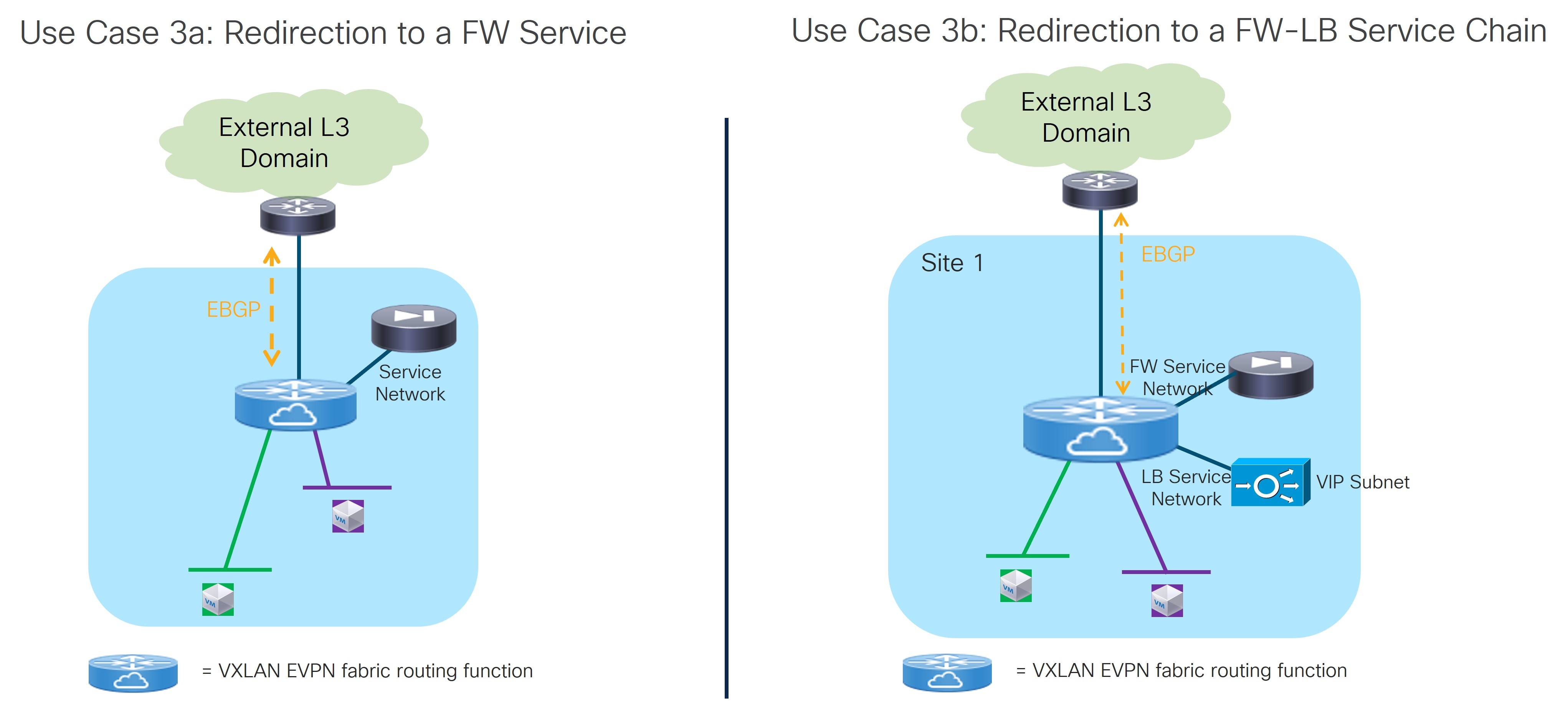
The service functions highlighted in the figure above are connected in “one arm mode”. This is the best practice deployment model, as it simplifies the routing configuration on the service function since a simple default route pointing to the IP address of the Service Network is all that you need.
The following sections provide more detail on the two types of Redirection to Service Chain use cases.
Use Case 3a: Redirection to a Firewall Service
Refer to the figure below for a graphical representation of the workflow for configuring the bidirectional Redirection to a Firewall Service use case (or more generically to a service function).
The provisioning steps shown in the figure below are going to be described in detail in the following sections. The number associated to each section matches the corresponding step in the diagram. Since the workflow moves back and forth between those steps, the numbering of the sections does not necessarily follow an ordered sequence.
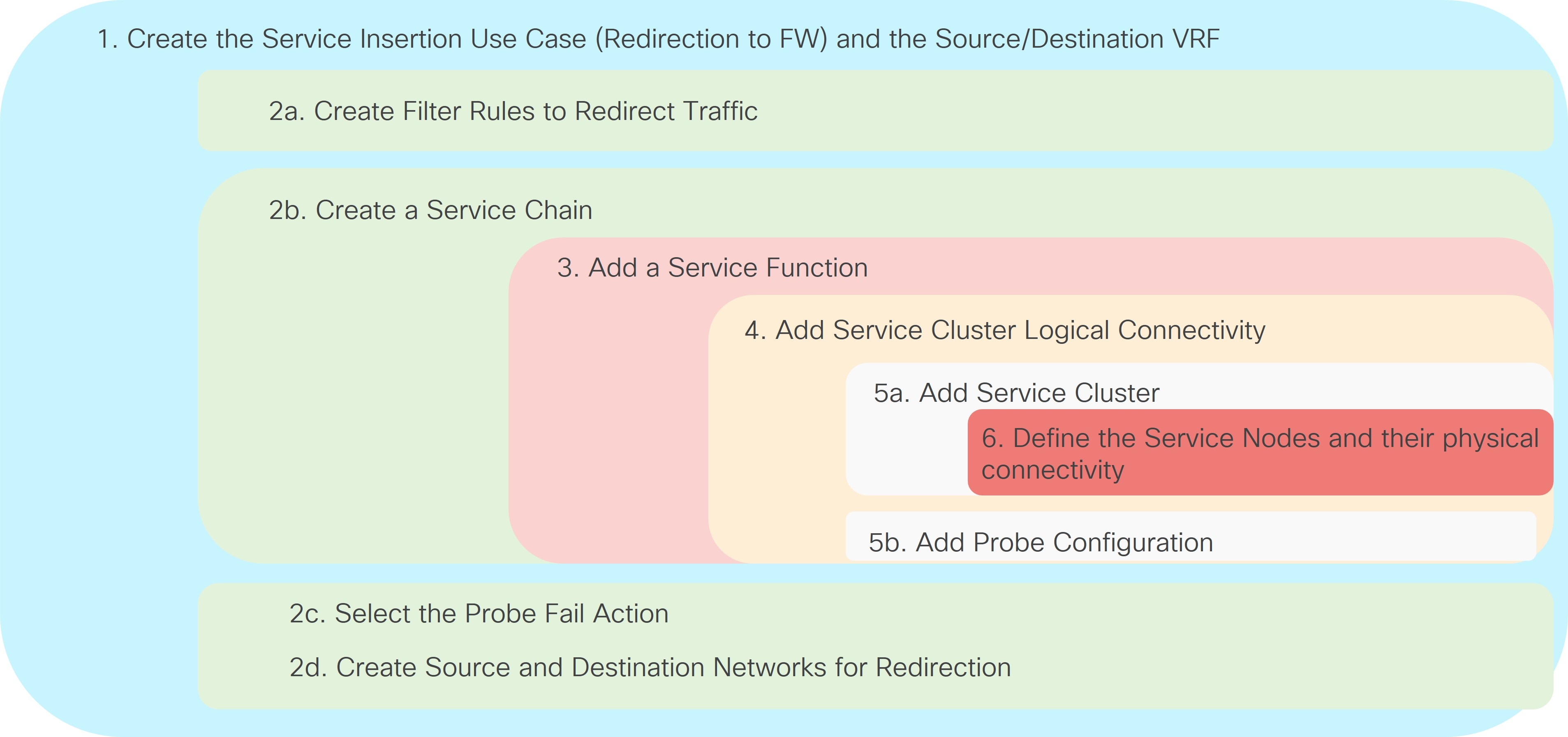
Figure 19 below shows a logical view of the traffic redirection functionality needed for flows between a source network and a destination network. As we describe in the steps below, those networks could be internal or external to the fabric, depending on whether the service redirection is required for east-west or north-south traffic flows.
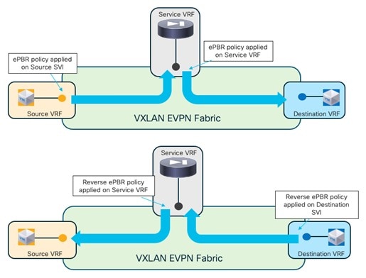
The source and destination networks could be part of the same VRF or different VRFs. You should deploy the Firewall Service function in a dedicated service VRF.
As shown in the figure above, the application of the service redirection policy on the interfaces for the source and destination networks ensure that the traffic can be redirected toward the service function in the correct service VRF (in other words, a “set-VRF” function is automatically performed in the source/destination VRFs to properly redirect the traffic flows toward the firewall in the Service VRF). The use of “set-VRF” in the source/destination VRFs ensures that the lookup for the firewall IP address is properly performed in the corresponding service VRF, allowing the required inter-VRF connectivity to establish properly.
An explicit user-driven configuration is instead required on NDFC 12.2.2 to leak the source/destination network routes into the service VRFs. This is needed because the ”set-VRF” function is not applicable to the ePBR policies applied at the service VRFs level (this configuration will be discussed in a specific configuration step below), so the required tenant’s routes must be leaked into the service VRF to establish the required inter-VRF connectivity.
1a. Select the Service Insertion Use Case (Redirect to Service Chain)
-
Navigate to the Service Insertions tab.
-
Navigate to:
Manage > Fabrics
-
Double-click the appropriate Data Center VXLAN EVPN fabric.
The Overview window for that fabric appears.
-
Click the Services tab.
-
Click the Service Insertions subtab.
A list of configured service insertion use cases is displayed.
-
-
Click Actions > Add Service Insertion.
The Add Service Insertion window is displayed.
-
Enter a name for the service insertion use case in the Service Insertion Name field.
The name can have alphanumeric, underscore, or dash characters. For example, for this particular use case, you might use
Redirect-to-FWas the service insertion name. -
In the Use Case field, choose the appropriate use case.
For this use case, you will choose Redirect to Service Chain as the use case.
-
Choose or create the VRF with the endpoints’ subnets.
-
In the Traffic Source VRF field, choose an existing traffic source VRF to associate with this service insertion use case, or click +Create VRF to create a new VRF.
-
In the Traffic Destination VRF field, choose existing traffic destination VRF to associate with this service insertion use case, or click +Create VRF to create a new VRF.
Refer to the section "VRFs" in About Fabric Overview for LAN Operational Mode Setups for more information.
In our specific example, you should use the same Tenant VRF (T1-VRF) for both the Traffic Source VRF and Traffic Destination VRF. However, performing a redirection for traffic between endpoints (or between endpoints and external networks) that are part of different Tenant VRFs is also supported.
-
-
In the Detach/Attach field, toggle the switch to detach or attach.
Selecting the Attach option is required to be able to provision the configuration to the switches at the end of the specific service insertion workflow. You can select the Attach option at this point, but we recommend that you do so at the end of the procedures, after you have completed all the steps in the configuration workflow.
-
In the Direction field, choose the direction for this service insertion use case.
Options are:
-
Bidirectional
-
Forward
-
Reverse
For this specific example, choose Bidirectional since the intent is to redirect both legs of each selected traffic flow to the firewall.
-
-
In the Enable Statistics field, check the check box to enable statistics for this service insertion use case.
Enabling statistics will track the number of packets that match the specific ePBR policy and that get redirected or service chained to the service functions. These statistics can also be later visualized in the form of a time series graph to understand the traffic redirection patterns.
-
In the Traffic Flow Redirects area, click + Add Traffic Flow Redirect and enter the necessary information to trigger the creation of traffic flow redirect.
-
In the Match ACL Name field, choose an already-configured access control list (ACL) from the drop-down list, or click +Create ACL to create a new access control list.
For this use case, we will click +Create ACL to create a new access control list. Go to 2a. Create the ACL Matching Traffic.
2a. Create the ACL Matching Traffic
You must create an ACL to define the specific protocols that should be redirected to the service function that you will be defining later in the sections below. In the simplest scenario where all the traffic between the source and destination networks should be redirected to the service function, for the ACL entry, you could simply specify ip in the Protocol field without configuring any source or destination ports.
-
In the Access Control List (ACL) Name field, enter a name for the new access control list.
-
In the Access List Entries area, click + Add Access List Entries.
-
Enter the necessary information to create a new access control list.
Field
Description
Sequence Number
Enter the sequence number for the ACL. Valid range: 1 - 4294967295.
Protocol
Specify the protocol to be used for the ACL. Options are:
-
icmp
-
ip
-
tcp
-
udp
Source IP
Enter a source IP address for the ACL. This entry can be an IPv4 address, an IPv6 address, or
any. Useanywhen you want to specify subnets as sources that are external to the fabric and that connect to the fabric through Layer 3 peering configured on the border leaf nodes.Destination IP
Enter a destination IP address for the ACL. This entry can be an IPv4 address, an IPv6 address, or
any. Useanywhen you want to specify subnets as sources that are external to the fabric and that connect to the fabric through Layer 3 peering configured on the border leaf nodes.Source Port
Enter the source port number (for example, any or 443). The value in this field is ignored if you selected ip or icmp in the Protocol field.
Destination Port
Enter the destination port number (for example, any or 443). The value in this field is ignored if you selected ip or icmp in the Protocol field.
In the specific scenario of redirection to a firewall function, the traffic originating from the source networks and destined to the destination networks (and vice versa) must always be steered to the firewall. Therefore, the required ACL should have entries that match the specific source/destination network(s) (you could use
anyin each entry for either the source or the destination network, as explained in the table above). -
-
Click the check mark to accept the access control list entries.
You are returned to the Add Service Insertion window, with the newly-created access control list displayed in the Match ACL Name field.
-
In the Match Action field, select the appropriate ACL match action.
Options are:
-
Redirect: The default action for matching traffic and redirecting to a service chain.
-
Drop: Match specific traffic and drop the traffic on the incoming interface
-
Exclude: Exclude certain traffic flows from the service chain on the incoming interface.
You can have only one Drop and one Exclude in the service insertion for a service chain.
-
-
In the Service Chain Name field, choose an already-configured service chain from the drop-down list, or click +Create Service Chain to create a new service chain.
For this use case, we will click +Create Service Chain to create a new service chain. Go to 2b. Create the Service Chain (Firewall Only).
2b. Create the Service Chain (Firewall Only)
In the specific example covered in this section, we consider a simple service chain containing a single service function (firewall). Any of the redundancy models discussed at the beginning of this article (such as active/standby cluster, active/active cluster, or a set of standalone nodes) could be considered for the deployment of the firewall service function. In our example, we’ll consider an active/standby cluster.
-
In the Add Service Chain window, enter a name for the service chain in the Service Chain Name field.
-
Click + Add Service Chain Entries.
-
Enter the necessary information for the service chain entries.
Field
Description
Sequence Number
Enter the sequence number. The lower the number in the sequence, the higher the priority.
In our specific example of firewall-only service chain, you can pick any sequence number for the firewall service function.
Service Cluster Type
Choose the type of service cluster. For this use case, we will choose Firewall.
VRF
Choose an existing VRF to associate with this service chain, or click + Create VRF to create a new VRF. Each service function part of a service chain should use a dedicated VRF, different from the VRF(s) used for the source and destination networks. In our example of a single firewall service in the chain, you can use a single firewall service VRF.
In the specific use case of intra-fabric redirection to a single service function, it is technically feasible (and supported) to deploy the service function in the same VRF of the source/destination networks. However, since the use of different VRFs is required when multiple service functions are part of the service-chain or for supporting service-redirection in a Multi-Site deployment, we recommend to always deploy each service function in its own dedicated VRF.
Service Function
Choose an existing service function to associate with this service chain, or click +Add Service Function to add a new service function.
Clicking +Add Service Function to create a new service function is the recommended approach as it ensures that the proper options (one-arm, two-arms, and so on) for the service function are automatically proposed based on the specific service insertion workflow that is being provisioned.
For this use case, we will click +Add Service Function to create a new service function. Go to 3. Add Service Function.
3. Add Service Function
In our example, the service chain contains only a firewall service function, so you will be performing the steps below only once. For more complex service chaining scenarios, you would repeat the same workflow covered below for each service function included in the chain.
-
In the Type field, choose the type of service function to be deployed.
For this use case, you will choose Firewall as the type of service function to be deployed.
-
In the Service Function Name field, enter a name for the service function.
The name can have alphanumeric, underscore, or dash characters.
-
In the Connectivity Mode field, choose One Arm or Two Arms.
We usually recommend the One Arm option as it simplifies the routing configuration on the service function (only a default route pointing to the IP address of the service network is required).
-
In the Service VRF field, choose the service VRF.
-
You should have a dedicated Service VRF for every service function that you create.
-
Configure route leaking from the tenant VRF(s) into the service VRF. You should only apply this route-leaking configuration to the service leaf nodes where the active and standby firewall nodes are connected, as it is required to ensure that traffic flows that went through the service function and are sent back to the fabric can be routed toward the destination in the specific Tenant VRF.
The recommended approach is to define a freeform template with the route-leaking configuration and apply the template only to the service leaf nodes.
Below is a simple example of a configuration that allows leak routes between a tenant VRF and a service VRF (the fabric’s BGP ASN used in this example is 65002).
Configuration of the Tenant VRF: “route-target auto” implies the use of the route-target as BGP-ASN:L3VNI (65002:50001).
vrf context t1-vrf1
 vni 50001
 rd auto
 address-family ipv4 unicast
   route-target both auto
   route-target both auto evpn
 address-family ipv6 unicast
   route-target both auto
   route-target both auto evpn
Configuration of the Service (firewall) VRF: Note the specific “import” statements to ensure that the tenant prefixes identified by the auto-generated RT value are imported in the service VRF routing table.
 vrf context t1-fw1-vrf1
  vni 50002
  rd auto
  address-family ipv4 unicast
    route-target both auto
    route-target both auto evpn
    route-target import 65002:50001
    route-target import 65002:50001 evpn
  address-family ipv6 unicast
    route-target both auto
    route-target both auto evpn
    route-target import 65002:50001
    route-target import 65002:50001 evpn
-
-
Click + Add Service Cluster Logical Connectivity.
The Add Service Cluster Logical Connectivity window appears. Go to 4a. Add Service Cluster Logical Connectivity to configure the logical connectivity for the service function.
4a. Add Service Cluster Logical Connectivity
-
In the Service Cluster Name field, select an already-configured service cluster, or click +Add Service Cluster to create a new one.
Before configuring the logical connectivity for the service function, you must define the service cluster implementing such a service function.
-
If you clicked +Add Service Cluster, go to 5a. Add Service Cluster.
-
If you choose an existing, already-configured service cluster for this use case, go to 4b. Add Service Cluster Logical Connectivity.
-
5a. Add Service Cluster
-
Verify the information in the Type field.
The Type field is automatically populated based on the service insertion use case that you chose in Step 1 in "Add Service Function".
-
Enter the necessary information to add a service cluster.
Field
Description
Service Cluster Name
Enter a name for the service cluster. The name can have alphanumeric, underscore, or dash characters.
Node Redundancy
Choose the node redundancy:
-
Standalone: Applicable if you are adding a single service node in the next step.
-
Active/Standby Cluster: Applicable if you are adding two service nodes in the next step, being part of the same Active/Standby cluster.
-
Active/Active Cluster: Applicable if you are adding two or more service nodes in the next step, being part of a single Active/Active cluster.
Form Factor
Select Physical or Virtual.
-
-
Click + Add Service Node.
The Add Service Node window appears. Go to 6. Add Service Nodes to define the service nodes part of the cluster and their physical connectivity to the fabric.
6. Add Service Nodes
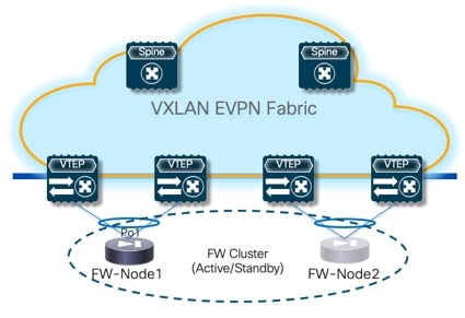
For the specific example described here, you will be configuring the two service nodes (FW-Node1 and FW-Node2, as part of the same Active/Standby cluster) as shown in the figure below.
As previously mentioned, you can also use an Active/Active cluster or a set of standalone nodes for the deployment of the service function.
-
Enter a name for the service node in the Service Node Name field.
For example,
FW-Node1. -
Click + Add Service Node Physical Connectivity to define how the node is physically connected to the fabric.
The Add Service Node Physical Connectivity window appears.
-
Enter the necessary information in the Add Service Node Connectivity window.
Field
Description
Service Node Name
Automatically populated with the service node name that you entered in the previous step.
Service Node Interface
Enter the service node interface. The service node interface is used for visualization and does not need to strictly match the name of any specific interface of the service node (even if it is operationally useful to do so).
Service Node Interface Usage
Choose the service node interface usage.
In the specific example shown in Figure 20, each service node is connected to a pair of service leaf nodes using a single vPC connection (different VLANs are trunked on that vPC to provide connectivity for the Service Network and the Inside Networks). Because of this, you will choose the Inside-Outside option for the Service Node Interface Usage. If separate physical interfaces are used instead for providing connectivity for the Service Network and the Inside Networks, you will have to choose separate Inside and Outside Service Node Interfaces.
Attached Switch
Select a switch or a switch pair from the list, depending on whether the service node is single-attached or dual-attached.
Switch Interface
Select the interface from the list.
-
If you selected a vPC pair in the Attached Switch list, a list of vPC port-channels defined on those switches will be shown in the Switch Interface list.
-
Otherwise, the port-channel and interfaces configured in trunk mode are shown in the Switch Interface list.
Link Template
Select the service_link_trunk, service_link_port_channel_trunk, or the service_link_vpc template from the drop-down list based on the specified attached switch interface type. For more information on template fields, see the section "Templates" in Layer 4 to Layer 7 Services Configuration.
-
-
Click Save after you have entered the necessary information in the Add Service Node Physical Connectivity window.
You are returned to the Add Service Node window.
-
Repeat the previous steps to add another service node interface, or click Save in the Add Service Node window to save the service node information.
You are returned to the Add Service Cluster window.
-
Click + Add Service Node, then repeat the steps in this section to add the second service node for this use case (
FW-Node2).When you have completed the steps to add the
FW-Node2service node, you should see information forFW-Node1andFW-Node2in the Service Nodes area in the Add Service Cluster window. -
Click Save in the Add Service Cluster window to save the service cluster information.
You are returned to the Add Service Cluster Logical Connectivity page. Continue to 4b. Add Service Cluster Logical Connectivity to complete the service cluster logical connectivity configurations.
4b. Add Service Cluster Logical Connectivity
At this point in these use case procedures, you have either selected an already-configured service cluster or you configured a new service cluster. Enter the necessary information to continue the process of adding service cluster logical connectivity.
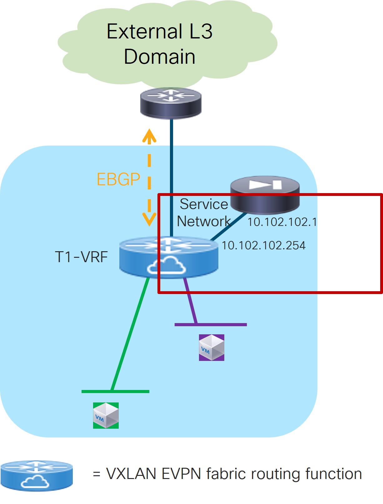
As shown in Figure 21, the firewall service function is connected in One Arm mode to the fabric using a Service Network, represented by a L2VNI segment with a configured anycast gateway address. There is no need to establish any routing peering (static or eBGP) between the fabric and the firewall, as the traffic redirection is applied to the firewall’s IP address that is part of the Service Network (directly connected to the fabric and redistributed into the EVPN fabric’s control plane).
-
In the IPv4 and/or IPv6 field, choose from the following options:
-
IPv4
-
IPv6
-
IPv4 and IPv6
In our example, we will be choosing IPv4.
-
-
Enter the necessary information in this window to complete the configuration of the service cluster logical connectivity.
The remaining fields in this window vary depending on the connectivity mode that you chose. For this example, if Two Arms was automatically selected based on the service insertion use case that you chose for this use case, the following fields would appear:
Field
Description
Service IPv4
Enter the firewall’s IPv4 and/or IPv6 service address.
For example, for this use case’s example configuration figure shown at the beginning of this section, you would enter
10.102.102.1in this field.Service IPv6
Service Network
Choose an existing service network to associate with this service function, or click +Add Service Network to create a new service network. Refer to the section "Networks" in About Fabric Overview for LAN Operational Mode Setups for more information.
If you were creating a new service network, for this use case’s example configuration figure shown at the beginning of this section, you would enter
10.102.102.254/24in the IPv4 Anycast Gateway/Netmask field. This value would appear in the Gateway IP field in the Service Network area in the Add Service Cluster Logical Connectivity window in this case.Probe
Choose an existing probe to associate with this service function, or click +Add Probe to create a new probe.
For this use case, we will click +Add Probe to add a probe configuration. Go to 5b. Add Probe Configuration.
5b. Add Probe Configuration
-
In the Add Probe Configuration window, enter a name for the probe in the Probe Name field.
-
In the Probe Template field, choose service_endpoint.
-
Enter the necessary information to configure the probe:
Field
Description
General Parameters
Enable Probe
Check the box to enable the probe of the next hop address.
Probing is performed from every leaf node in the fabric. The source interface used for probing is a loopback interface defined on each leaf node in the Service VRF. The provisioning of those loopbacks mandate to set the Per VRF Per VTEP Loopback IPv4 Auto-Provisioning and Per VRF Per VTEP Loopback IPv6 Auto-Provisioning fields under Resources for that fabric. Refer to Data Center VXLAN EVPN for more information.
When enabling the Per VRF Per VTEP Loopback options above, loopback addresses will be assigned to each VTEP for all the VRFs that are locally defined. The IP addresses to be assigned for those loopback addresses are taken from a global pool specified at the fabric level. In the NDFC 12.2.2 release, it is permitted to assign overlapping IP addresses to loopback addresses assigned to different VTEPs in different VRFs. This could create issues when VRF leaking is configured between the tenant VRF(s) and the Service-FW and Service-LB VRFs. We therefore strongly recommend that you manually assign those loopback addresses (it can be done at the VRF level for each VTEP in the fabric) to ensure their uniqueness inside and across the defined VRFs.
Protocol
Specify the protocol to be used for the probe. Options are:
-
icmp
-
tcp
-
udp
-
http
Port Number
Displayed for input only if the protocol is tcp or udp. Enter the port number for the probe. Valid ranges: 1-65535 (recommended range:1025-65534).
User Input for HTTP Probe
Displayed for input only if the protocol is http. Enter a user input text/filename for an HTTP probe (for example: http://192.168.50.254/index.html). Maximum size: 99.
Advanced
Threshold
Enter the threshold value, in seconds. Valid range: 1 - 60.
Frequency
Enter the frequency value in seconds. Valid range: 1 - 604800.
Delay Down Change Notification
Enter the delay down change notification value, in seconds. Valid range: 1 - 180.
Delay Up Change Notification
Enter the delay up change notification value, in seconds. Valid range: 1 - 180.
Timeout
Enter the timeout value, in seconds. Valid range: 1 - 604800.
For more information on the configuration of probes for service redirection, refer to the NX-OS configuration guide.
-
-
Continue to 4c. Add Service Cluster Logical Connectivity.
4c. Add Service Cluster Logical Connectivity
-
In the Peering Option field, choose the appropriate peering option to associate with this service function.
For this use case, choose Connected as the peering option, as redirection is to the firewall IP address that is connected to the previously-defined FW-Service-Network.
-
Continue to 2c. Select the Probe Fail Action.
2c. Select the Probe Fail Action
-
In the Probe Fail Action field in the Add Service Chain window, select the appropriate probe fail action.
Options are:
-
Forward: Default option where traffic should use the regular routing tables.
-
Drop: Traffic is dropped when service becomes unreachable.
-
Bypass: Traffic is redirected to the next service sequence when there is a failure of the current sequence.
-
None
-
-
Click the check mark to accept the values for the service chain entries.
You are returned to the Add Service Insertion window. Continue to 2d. Create/Select the Source and Destination Networks.
2d. Create/Select the Source and Destination Networks
As the result of the access control list created in step 2a, the matching source and destination networks part of the Source and Destination VRFs configured in step 1a are going to be pre-populated in the Networks area. Those entries are needed to indicate to NDFC the interfaces that need to have the ePBR policy applied. Normally, there should be no need to modify those entries, except for the specific case where the source or the destination networks are configured with the any keyword (note that it is not possible to use any in the same entry both as source and destination networks).
The use of any as the source or destination networks represents your intent to specify prefixes that are external to the fabric. A rule using any as the source means that the source of the flow is a client connected to the external network domain. Conversly, a rule using any as the destination means that the destination of the flow is a client that is external to the fabric. Since the external network domain must be reachable through border leaf nodes, the UI mandates that you must specify the interfaces of the border leaf nodes that are used to connect to the external domain for the source (or destination) any network.
-
In the Networks area, click + Add Row and enter the necessary information:
Field
Description
Source Network
The source and destination network fields are auto-populated based on the ACL entries in the selected or newly created ACL. You can override the system auto-populated source and/or destination network.
If you want to override the system auto-populated source and/or destination network, choose an already-configured source and/or destination network from the drop-down list, or click +Create Network to create a new network. Refer to the section "Networks" in About Fabric Overview for LAN Operational Mode Setups for more information.
Destination Network
Source Switch (Interfaces)
Choose the interfaces of the border leaf nodes connecting to the external network domain. This configuration is required when
anyis configured as the source network.Destination Switch (Interfaces)
Choose the interfaces of the border leaf nodes connecting to the external network domain. This configuration is required when
anyis configured as destination network,. -
When you have completed the configuration for this network, click the check mark at the end of the row to accept the values that you entered.
Repeat these steps to configure additional networks.
-
Click Save after you have entered the necessary information to add a service insertion with this use case.
You are returned to the Fabric Overview page, with Services > Service Insertions selected.
Attach and Deploy the Use Case
NDFC 12.2.2 displays an error if the service VRF associated to the Service Function is not deployed on the compute leaf nodes. Therefore, you must deploy the service VRF to the compute leaf nodes before moving to step 1 below.
-
Check the box next to the new service insertion and click the lower (white) Actions dropdown, then select Attach.
After several seconds, the value shown in the Attached column changes to True.
-
Click the upper (blue) Actions dropdown, then select Recalculate and Deploy.
The new configurations are now deployed to the service leaf nodes.
Use Case 3b: Redirection to a Firewall-Load Balancer Service Chain
Refer to the figure below for a graphical representation of the workflow for configuring the Redirection to a Firewall-Load Balancer Service Chain use case.
The provisioning steps shown in the figure below are going to be described in detail in the following sections. The number associated to each section matches the corresponding step in the diagram. Since the workflow moves back and forth between those steps, the numbering of the sections does not necessarily follow an ordered sequence.
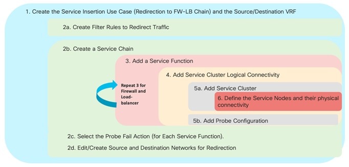
The basic assumption is that the load-balancer is not performing Source-NAT (SNAT), which implies the need to leverage service redirection to steer the traffic flows between the server farm and the clients back to the load-balancer.
Figure 23 below shows a logical view of the traffic redirection functionality needed for flows between a source network (clients) and a destination network (server farm), and vice versa. As we describe in the steps below, those networks could be internal or external to the fabric, depending on whether the service redirection is required for east-west or north-south traffic flows.
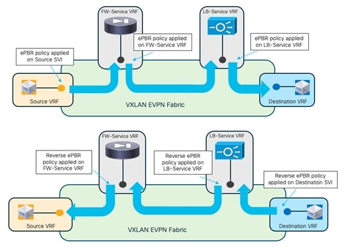
The source and destination networks could be part of the same VRF or different VRFs. You must deploy the Firewall and Load-Balancer Service functions each in a dedicated Service VRF (FW-Service VRF and LB-Service VRF).
As shown in the figure above, depending on the direction of the flows, the service redirection policy is applied on the source (or destination) SVIs and on the service VRFs to ensure that flows are steered through both of the service functions that are part of the chain. A “set-vrf” function is automatically performed in the source/destination VRFs to properly redirect the traffic flows toward the service functions in the service VRFs. The use of “set-VRF” in the source/destination VRFs ensures that the lookup for the firewall (or the load-balancer) IP address is properly performed in the corresponding service VRF, allowing the required inter-VRF connectivity to establish properly.
The application of the ePBR policy in the FW-Service VRF is needed only to enable the inter-VRF connectivity. This is because the destination of traffic flows initiated from the source networks (clients) is always the load-balancer VIP address that is reachable in a different LB-Service VRF.
An explicit user-driven configuration is required to leak the source/destination network routes into the service VRFs. More specifically, the destination network routes must be leaked into the VRF of the last service function in the chain (the Load-Balancer in our example), whereas the source network routes must be leaked into the VRF of the first service function in the chain (the Firewall in our example).
The specific route-leaking configuration needs to be provisioned only on the service leaf nodes where the service functions are connected and will be discussed in a specific configuration step below.
1. Select the Service Insertion Use Case (Redirect to Service Chain)
-
Navigate to the Service Insertions tab.
-
Navigate to:
Manage > Fabrics
-
Double-click the appropriate Data Center VXLAN EVPN fabric.
The Overview window for that fabric appears.
-
Click the Services tab.
-
Click the Service Insertions subtab.
A list of configured service insertion use cases is displayed.
-
-
Click Actions > Add Service Insertion.
The Add Service Insertion window is displayed.
-
Enter a name for the service insertion use case in the Service Insertion Name field.
The name can have alphanumeric, underscore, or dash characters. For example, for this particular use case, you might use
Redirect-to-FW-LB-chainas the service insertion name. -
In the Use Case field, choose the appropriate use case.
For this use case, you will choose Redirect to Service Chain as the use case.
-
Choose or create the VRF with the endpoints’ subnets.
-
In the Traffic Source VRF field, choose an existing traffic source VRF to associate with this service insertion use case, or click +Create VRF to create a new VRF.
-
In the Traffic Destination VRF field, choose existing traffic destination VRF to associate with this service insertion use case, or click +Create VRF to create a new VRF.
Refer to the section "VRFs" in About Fabric Overview for LAN Operational Mode Setups for more information.
In our specific example, you should use the same Tenant VRF (T1-VRF) for both the Traffic Source VRF and Traffic Destination VRF. However, performing redirection for traffic between endpoints (or between endpoints and external networks) that are part of different Tenant VRFs is also supported.
-
-
In the Detach/Attach field, toggle the switch to detach or attach.
Selecting the Attach option is required to be able to provision the configuration to the switches at the end of the specific service insertion workflow. You can select the Attach option at this point but we recommend that you do so at the end of the procedures, after you have completed all the steps in the configuration workflow.
-
In the Direction field, choose the direction for this service insertion use case.
Options are:
-
Bidirectional
-
Forward
-
Reverse
For this specific example, choose Bidirectional since the intent is to redirect both legs of each selected traffic flow to the chain of firewall and load-balancer service functions, as shown in Figure 23.
-
-
In the Enable Statistics field, check the check box to enable statistics for this service insertion use case.
Enabling statistics will track the number of packets that match the specific ePBR policy and that get redirected or service chained to the service functions. These statistics can also be later visualized in the form of a time series graph to understand the traffic redirection patterns.
-
In the Traffic Flow Redirects area, click + Add Traffic Flow Redirect and enter the necessary information to trigger the creation of traffic flow redirect.
-
In the Match ACL Name field, choose an already-configured access control list (ACL) from the drop-down list, or click +Create ACL to create a new access control list.
For this use case, we will click +Create ACL to create a new access control list. Go to 2a. Create the ACL Matching Traffic.
2a. Create the ACL Matching Traffic
You must create an ACL to define the specific traffic flows that should be redirected to the service function(s) that you will be defining later in the sections below. In the simplest scenario where all the traffic should be redirected to a service function (or a chain of service functions), you can simply specify the ACL entry as ip in the Protocol field without configuring any source or destination port.
In the specific scenario of a firewall/load-balancer chain, the traffic originating from the source network (client) is always destined to the load-balancer VIP address, whereas the return flows originating from the destination network (server farm) are always destined to the source network (client). Therefore, the required ACL should be defined with (at least) two entries:
-
The first one to match the client network as the source (you could use
anyif the client is connected to the network that is external to the fabric) and the load-balancer VIP as the destination. This is used to redirect first to the firewall the traffic originating from the clients and destined to the VIP. As previously mentioned, even for traffic originating from the client and destined to the LB VIP, a double service redirection is technically performed to enable the “set ip next-hop + VRF” functionality that allows the fabric to send the traffic that has gone through the firewall service function to the load balancer VIP (the top part of Figure 23). -
The second one to match the client network as the source (you could use
anyif the client is connected to the network that is external to the fabric) and the server farm network(s) as the destination. This entry is only matched for the reverse flows originating from the server farm and destined to the clients, and is used to redirect the traffic first to the load-balancer and then to the firewall (the bottom part of Figure 23).
The assumption is that there is no need for direct communication between the source network (clients) and the destination network (server-farm). If that is the case, those traffic flows would be redirected to the service chain in virtue of the second ACL entry defined above.
-
In the Access Control List (ACL) Name field, enter a name for the new access control list.
For example,
ACL-Traffic-to-ServiceChain. -
In the Access List Entries area, click + Add Access List Entries.
-
Enter the necessary information to create a new access control list.
Field
Description
Sequence Number
Enter the sequence number for the ACL. Valid range: 1 - 4294967295.
Protocol
Specify the protocol to be used for the ACL. Options are:
-
icmp
-
ip
-
tcp
-
udp
Source IP
Enter a source IP address for the ACL. This entry can be an IPv4 address, an IPv6 address, or
any. Useanywhen you want to specify subnets that are external to the fabric as sources and that connect to internal endpoints through Layer 3 peering configured on the border leaf nodes. Otherwise, configure the IP prefix for the client’s subnet internal to the fabric.Destination IP
Enter a destination IP address for the ACL. This entry can be an IPv4 address, an IPv6 address, or
any. Useanywhen you want to specify subnets that are external to the fabric as sources and that connect to internal endpoints through Layer 3 peering configured on the border leaf nodes. Otherwise, configure the IP prefix for the client’s subnet internal to the fabric.Source Port
Enter the source port number (for example, any or 443). The value in this field is ignored if you selected ip or icmp in the Protocol field.
Destination Port
Enter the destination port number (for example, any or 443). The value in this field is ignored if you selected ip or icmp in the Protocol field.
-
-
Click the check mark to accept the access control list entries.
You are returned to the Add Service Insertion window, with the newly-created access control list displayed in the Match ACL Name field.
-
In the Match Action field, select the appropriate ACL match action.
Options are:
-
Redirect: The default action for matching traffic and redirecting to a service chain.
-
Drop: Match specific traffic and drop the traffic on the incoming interface
-
Exclude: Exclude certain traffic flows from the service chain on the incoming interface.
For this use case, we will choose Redirect as the match action.
You can have only one Drop and one Exclude in the service insertion for a service chain.
-
-
In the Service Chain Name field, choose an already-configured service chain from the drop-down list, or click +Create Service Chain to create a new service chain.
For this use case, we will click +Create Service Chain to create a new service chain. Go to 2b. Create the Service Chain (Firewall and Load Balancer).
2b. Create the Service Chain (Firewall and Load Balancer)
In the specific example covered in this section, we consider a service chain containing a firewall and a load-balancer. Any of the redundancy models discussed at the beginning of this article (such as active/standby cluster, active/active cluster, and a set of standalone nodes) could be considered for the deployment of the firewall and load-balancer service functions. In our example, we’ll consider active/standby clusters.
-
In the Add Service Chain window, enter a name for the service chain in the Service Chain Name field.
For example,
Redirect_to_FW-LB_Chain. -
Click + Add Service Chain Entries.
-
Enter the necessary information for the service chain entries.
Field
Description
Sequence Number
Enter the sequence number. The lower the number in the sequence, the higher the priority.
In our example, since you have two service functions defined in the service chain, you will configure the following entries:
-
Firewall, with a sequence number of 10
-
Load balancer, with a sequence number of 20
Then the firewall, with a sequence number of 10, will be higher priority and will be triggered first in the sequence, followed by the load balancer with a sequence number of 20.
Service Cluster Type
Choose the type of service cluster. For this use case, we will choose Firewall first and then Load Balancer.
VRF
Choose an existing VRF to associate with this service chain, or click + Create VRF to create a new VRF. Each service function part of a service chain should use a dedicated VRF, different from the VRF(s) used for the source and destination networks. In our example, a unique service VRF will be deployed for each service function part of the chain.
Service Function
Choose an existing service function to associate with this service chain, or click +Add Service Function to add a new service function.
Clicking +Add Service Function to create a new service function is the recommended approach as it ensures that the proper options (one-arm, two-arms, and so on) for the service function are automatically proposed based on the specific service insertion workflow that is being provisioned.
For this use case, we will click +Add Service Function to create a new service function. Go to 3a. Add Service Function (Firewall) and [3b. Add Service Function (Load-Balancer)].
-
3a. Add Service Function (Firewall)
-
In the Type field, choose the type of service function to be deployed.
For this use case, you will choose Firewall as the type of service function to be deployed.
-
In the Service Function Name field, enter a name for the service function.
The name can have alphanumeric, underscore, or dash characters.
-
In the Connectivity Mode field, choose One Arm or Two Arms.
We usually recommend the One Arm option as it simplifies the routing configuration on the service function (only a default route pointing to the IP address of the service network is required).
-
In the Service VRF field, choose the service VRF.
You should have a dedicated Service VRF for every service function that you create. In this service chain use case, you will define a Service-FW VRF that will be used for the firewall service function and a Service-LB VRF that will be used for the load balancer service function.
At the end of the service insertion workflow, you will also need to configure route-leaking from the tenant VRF of the source network(s) and the Service-FW VRF. As previously mentioned, this is required to ensure that return flows (between the server farm and the clients) can be successfully routed to the clients after being sent back to the fabric from the firewall service function.
The route-leaking configuration between the source network(s) and the Service-FW VRF should only be applied to the service leaf nodes where the firewall nodes are connected. With the NDFC 12.2.2 release, we recommend that you define a freeform template with the route-leaking configuration and apply the template to those service leaf nodes.
Below is a simple example of a configuration that allows leak routes belonging to the tenant VRF of the source network(s) and the Service-FW VRF (the BGP ASN used in this example is 65002).
Configuration of the tenant VRF: The use of “route-target auto” implies the definition of the route-target as BGP-ASN:L3VNI (65002:50001).
vrf context t1-vrf
 vni 50001
 rd auto
 address-family ipv4 unicast
   route-target both auto
   route-target both auto evpn
 address-family ipv6 unicast
   route-target both auto
   route-target both auto evpn
Configuration of the Service-FW VRF: Note the specific “import” statements to ensure that the prefixes from the Tenant VRF are imported in the Service-FW VRF routing table.
vrf context t1-fw-vrf vni 50002 rd auto address-family ipv4 unicast route-target both auto route-target both auto evpn route-target import 65002:50001 route-target import 65002:50001 evpn address-family ipv6 unicast route-target both auto route-target both auto evpn route-target import 65002:50001 route-target import 65002:50001 evpn -
Click + Add Service Cluster Logical Connectivity.
The Add Service Cluster Logical Connectivity window appears. Go to 4a. Add Service Cluster Logical Connectivity (Firewall) to configure the logical connectivity for the service function.
4a. Add Service Cluster Logical Connectivity (Firewall)
-
In the Service Cluster Name field, select an already-configured service cluster, or click +Add Service Cluster to create a new one.
Before configuring the logical connectivity for the service function, you must define the service cluster implementing such a service function.
-
If you clicked +Add Service Cluster, go to 5a. Add Service Cluster (Firewall).
-
If you choose an existing, already-configured service cluster for this use case, go to 4b. Add Service Cluster Logical Connectivity (Firewall).
-
5a. Add Service Cluster (Firewall)
-
Verify the information in the Type field.
The Type field is automatically populated based on the service insertion use case that you chose in Step 1 in "Add Service Function".
-
Enter the necessary information to add a service cluster.
Field
Description
Service Cluster Name
Enter a name for the service cluster. The name can have alphanumeric, underscore, or dash characters.
Node Redundancy
Choose the node redundancy:
-
Standalone: Applicable if you are adding a single service node in the next step.
-
Active/Standby Cluster: Applicable if you are adding two service nodes in the next step, being part of the same Active/Standby cluster.
-
Active/Active Cluster: Applicable if you are adding two or more service nodes in the next step, being part of a single Active/Active cluster.
Form Factor
Select Physical or Virtual.
-
-
Click + Add Service Node.
The Add Service Node window appears. Go to 6. Add Service Nodes (Firewall) to define the service nodes part of the cluster and their physical connectivity to the fabric.
6. Add Service Nodes (Firewall)
For the specific example described here, you will be configuring the two service nodes (FW-Node1 and FW-Node2, as part of the same Active/Standby cluster) as shown in the figure below.
As previously mentioned, you can also use an Active/Active cluster or a set of standalone nodes for the deployment of the service function.

-
Enter a name for the service node in the Service Node Name field.
For example,
FW-Node1. -
Click + Add Service Node Physical Connectivity to define how the node is physically connected to the fabric.
The Add Service Node Physical Connectivity window appears.
-
Enter the necessary information in the Add Service Node Connectivity window.
Field
Description
Service Node Name
Automatically populated with the service node name that you entered in the previous step.
Service Node Interface
Enter the service node interface. The service node interface is used for visualization and does not need to strictly match the name of any specific interface of the service node (even if it is operationally useful to do so).
Service Node Interface Usage
Choose the service node interface usage.
In the specific example shown in the previous figure, each service node is connected to a pair of service leaf nodes using a single vPC connection (different VLANs are trunked on that vPC to provide connectivity for the Service Network and the Inside Networks). Because of this, you will choose the Inside-Outside option for the Service Node Interface Usage. If separate physical interfaces are used instead for providing connectivity for the Service Network and the Inside Networks, you will have to choose separate Inside and Outside Service Node Interfaces.
Attached Switch
Select a switch or a switch pair from the list, depending on whether the service node is single-attached or dual-attached.
Switch Interface
Select the interface from the list.
-
If you selected a vPC pair in the Attached Switch list, a list of vPC port-channels defined on those switches will be shown in the Switch Interface list.
-
Otherwise, the port-channel and interfaces configured in trunk mode are shown in the Switch Interface list.
Link Template
Select the service_link_trunk, service_link_port_channel_trunk, or the service_link_vpc template from the drop-down list based on the specified attached switch interface type. For more information on template fields, see the section "Templates" in Layer 4 to Layer 7 Services Configuration.
-
-
Click Save after you have entered the necessary information in the Add Service Node Physical Connectivity window.
You are returned to the Add Service Node window.
-
Repeat the previous steps to add another service node interface, or click Save in the Add Service Node window to save the service node information.
You are returned to the Add Service Cluster window.
-
Click + Add Service Node, then repeat the steps in this section to add the second service node for this use case (
FW-Node2).When you have completed the steps to add the
FW-Node2service node, you should see information forFW-Node1andFW-Node2in the Service Nodes area in the Add Service Cluster window. -
Click Save in the Add Service Cluster window to save the service cluster information.
You are returned to the Add Service Cluster Logical Connectivity page. Continue to 4b. Add Service Cluster Logical Connectivity (Firewall) to complete the service cluster logical connectivity configurations.
4b. Add Service Cluster Logical Connectivity (Firewall)
At this point in these use case procedures, you have either selected an already-configured service cluster or you configured a new service cluster. Enter the necessary information to continue the process of adding service cluster logical connectivity.
As shown in Figure 25, the firewall service function is connected in One Arm mode to the fabric using a Service Network, represented by a L2VNI segment with a configured anycast gateway address. You do not have to establish any routing peering (static or EBGP) between the fabric and the firewall, as the traffic redirection is done to the firewall’s IP address that is part of the Service Network (directly connected to the fabric and therefore redistributed into the EVPN fabric’s control plane).

-
In the IPv4 and/or IPv6 field, choose from the following options:
-
IPv4
-
IPv6
-
IPv4 and IPv6
In our example, we will be choosing IPv4.
-
-
Enter the necessary information in this window to complete the configuration of the service cluster logical connectivity.
The remaining fields in this window vary depending on the connectivity mode that you chose. For this example, if you selected the recommended Two Arms option, the following fields would appear:
Field
Description
Service IPv4
Enter the firewall’s IPv4 and/or IPv6 service address.
For example, for this use case’s example configuration figure shown at the beginning of this section, you would enter
10.102.102.1in this field.Service IPv6
Service Network
Choose an existing service network to associate with this service function, or click +Add Service Network to create a new service network. Refer to the section "Networks" in About Fabric Overview for LAN Operational Mode Setups for more information.
If you were creating a new service network, for this use case’s example configuration figure shown at the beginning of this section, you would enter
10.102.102.254/24in the IPv4 Anycast Gateway/Netmask field. This value would appear in the Gateway IP field in the Service Network area in the Add Service Cluster Logical Connectivity window in this case.Probe
Choose an existing probe to associate with this service function, or click +Add Probe to create a new probe.
For this use case, we will click +Add Probe to add a probe configuration. Go to 5b. Add Probe Configuration (Firewall).
5b. Add Probe Configuration (Firewall)
-
In the Add Probe Configuration window, enter a name for the probe in the Probe Name field.
-
In the Probe Template field, choose service_endpoint.
-
Enter the necessary information to configure the probe:
Field
Description
General Parameters
Enable Probe
Check the box to enable the probe of the (reversed) next hop address.
Probing is performed from every leaf node in the fabric. The source interface used for probing is a loopback interface defined on each leaf in the Service VRF. The provisioning of those loopbacks mandate to set the Per VRF Per VTEP Loopback IPv4 Auto-Provisioning and Per VRF Per VTEP Loopback IPv6 Auto-Provisioning fields under Resources for that fabric. Refer to Data Center VXLAN EVPN for more information.
When enabling the “Per VRF Per VTEP Loopback” options above, loopback addresses will be assigned to each VTEP for all the VRFs that are locally defined. The IP addresses to be assigned for those loopback addresses are taken from a global pool specified at the fabric level. In the NDFC 12.2.2 release, it is permitted to assign overlapping IP addresses to loopback addresses assigned to different VTEPs in different VRFs. This could create issues when VRF leaking is configured between the tenant VRF(s) and the Service-FW and Service-LB VRFs. We therefore strongly recommend that you manually assign those loopback addresses (it can be done at the VRF level for each VTEP in the fabric) to ensure their uniqueness inside and across the defined VRFs.
Protocol
Specify the protocol to be used for the probe. Options are:
-
icmp
-
tcp
-
udp
-
http
Port Number
Displayed for input only if the protocol is tcp or udp. Enter the port number for the probe. Valid ranges: 1-65535 (recommended range:1025-65534).
User Input for HTTP Probe
Displayed for input only if the protocol is http. Enter a user input text/filename for an HTTP probe (for example: http://192.168.50.254/index.html). Maximum size: 99.
Advanced
Threshold
Enter the threshold value, in seconds. Valid range: 1 - 60.
Frequency
Enter the frequency value in seconds. Valid range: 1 - 604800.
Delay Down Change Notification
Enter the delay down change notification value, in seconds. Valid range: 1 - 180.
Delay Up Change Notification
Enter the delay up change notification value, in seconds. Valid range: 1 - 180.
Timeout
Enter the timeout value, in seconds. Valid range: 1 - 604800.
For more information on the configuration of probes for service redirection, refer to the NX-OS configuration guide.
-
-
Continue to 4c. Add Service Cluster Logical Connectivity (Firewall).
4c. Add Service Cluster Logical Connectivity (Firewall)
-
In the Peering Option field, choose the appropriate peering option to associate with this service function.
For this use case, choose Connected as the peering option, as redirection is to the firewall IP address that is connected to the previously-defined FW-Service-Network.
-
Click Save and return to the Add Service Chain window.
-
Continue to 2c. Select the Probe Fail Action (Firewall).
2c. Select the Probe Fail Action (Firewall)
-
In the Probe Fail Action field in the Add Service Chain window, select the appropriate probe fail action.
Options are:
-
Forward: Default option where traffic should use the regular routing tables.
-
Drop: Traffic is dropped when service becomes unreachable.
-
Bypass: Traffic is redirected to the next service sequence when there is a failure of the current sequence.
-
None
-
-
Click the check mark to accept the values for the service chain firewall entry.
-
Continue to 3b. Add Service Function (Load Balancer).
3b. Add Service Function (Load Balancer)
-
In the Type field, choose the type of service function to be deployed.
For this use case, you will choose Load Balancer as the type of service function to be deployed.
-
In the Service Function Name field, enter a name for the service function.
The name can have alphanumeric, underscore, or dash characters.
-
In the Connectivity Mode field, choose One Arm or Two Arms.
We usually recommend the One Arm option as it simplifies the routing configuration on the service function (only a default route pointing to the IP address of the service network is required).
-
In the Service VRF field, choose the service VRF.
You should have a dedicated Service VRF for every service function that you create. In this service chain use case, you will define a Service-FW VRF and a Service-LB VRF.
At the end of the service insertion workflow, you will also need to configure route-leaking from the tenant VRF of the destination network(s) and the Service-LB VRF. As previously mentioned, this is required to ensure that flows originated by the clients can be successfully sent to the server-farm after being sent back to the fabric from the load balancer service function.
The route-leaking configuration between the destination network(s) and the Service-LB VRF should only be applied to the service leaf nodes where the load balancer nodes are connected. With NDFC 12.2.2 release, we recommend that you define a freeform template with the route-leaking configuration and apply the template to those service leaf nodes.
We recommend that you define a freeform template on NDFC with the route-leaking configuration and apply the template to the service leaf nodes.
Below is a simple example of a configuration allowing to leak routes belonging to the tenant VRF of the destination network(s) and the Service-LB VRF (the BGP ASN used in this example is 65002).
Configuration of the tenant VRF: The use of “route-target auto” implies the definition of the route-target as BGP-ASN:L3VNI (65002:50001).
vrf context t1-vrf
 vni 50001
 rd auto
 address-family ipv4 unicast
   route-target both auto
   route-target both auto evpn
 address-family ipv6 unicast
   route-target both auto
   route-target both auto evpn
Configuration of the Service-LB VRF: Note the specific “import” statements to ensure that the prefixes from the Tenant VRF are imported in the Service-LB VRF routing table.
vrf context t1-lb-vrf vni 50003 rd auto address-family ipv4 unicast route-target both auto route-target both auto evpn route-target import 65002:50001 route-target import 65002:50001 evpn address-family ipv6 unicast route-target both auto route-target both auto evpn route-target import 65002:50001 route-target import 65002:50001 evpn -
Click + Add Service Cluster Logical Connectivity.
The Add Service Cluster Logical Connectivity window appears. Go to 4a. Add Service Cluster Logical Connectivity (Load Balancer) to configure the logical connectivity for the service function.
4a. Add Service Cluster Logical Connectivity (Load Balancer)
-
In the Service Cluster Name field, select an already-configured service cluster, or click +Add Service Cluster to create a new one.
Before configuring the logical connectivity for the service function, you must define the service cluster implementing such a service function.
-
If you clicked +Add Service Cluster, go to 5a. Add Service Cluster (Load Balancer).
-
If you choose an existing, already-configured service cluster for this use case, go to 4b. Add Service Cluster Logical Connectivity (Load Balancer).
-
5a. Add Service Cluster (Load Balancer)
-
Verify the information in the Type field.
The Type field is automatically populated based on the service insertion use case that you chose in Step 1 in "Add Service Function".
-
Enter the necessary information to add a service cluster.
Field
Description
Service Cluster Name
Enter a name for the service cluster. The name can have alphanumeric, underscore, or dash characters.
Node Redundancy
Choose the node redundancy:
-
Standalone: Applicable if you are adding a single service node in the next step.
-
Active/Standby Cluster: Applicable if you are adding two service nodes in the next step, being part of the same Active/Standby cluster.
-
Active/Active Cluster: Applicable if you are adding two or more service nodes in the next step, being part of a single Active/Active cluster.
For the specific example described here, you will choose Standalone for the node redundancy.
Form Factor
Select Physical or Virtual.
-
-
Click + Add Service Node.
The Add Service Node window appears. Go to 6. Add Service Nodes (Load Balancer) to define the service nodes part of the cluster and their physical connectivity to the fabric.
6. Add Service Nodes (Load Balancer)
For the specific example described here, you will be configuring one service nodes (LB-Node1).
-
Enter a name for the service node in the Service Node Name field.
For example,
LB-Node1. -
Click + Add Service Node Physical Connectivity to define how the node is physically connected to the fabric.
The Add Service Node Physical Connectivity window appears.
-
Enter the necessary information in the Add Service Node Connectivity window.
Field
Description
Service Node Name
Automatically populated with the service node name that you entered in the previous step.
Service Node Interface
Enter the service node interface. The service node interface is used for visualization and does not need to strictly match the name of any specific interface of the service node (even if it is operationally useful to do so).
Service Node Interface Usage
Choose the service node interface usage.
For the specific example described here, you will choose First-Second Arm.
Attached Switch
Select a switch or a switch pair from the list, depending on whether the service node is single-attached or dual-attached.
Switch Interface
Select the interface from the list.
-
If you selected a vPC pair in the Attached Switch list, a list of vPC port-channels defined on those switches will be shown in the Switch Interface list.
-
Otherwise, the port-channel and interfaces configured in trunk mode are shown in the Switch Interface list.
Link Template
Select the service_link_trunk, service_link_port_channel_trunk, or the service_link_vpc template from the drop-down list based on the specified attached switch interface type. For more information on template fields, see the section "Templates" in Layer 4 to Layer 7 Services Configuration.
-
-
Click Save after you have entered the necessary information in the Add Service Node Physical Connectivity window.
You are returned to the Add Service Node window.
-
Repeat the previous steps to add another service node interface, or click Save in the Add Service Node window to save the service node information.
You are returned to the Add Service Cluster window.
-
Click Save in the Add Service Cluster window to save the service cluster information.
You are returned to the Add Service Cluster Logical Connectivity page. Continue to 4b. Add Service Cluster Logical Connectivity (Load Balancer) to complete the service cluster logical connectivity configurations.
4b. Add Service Cluster Logical Connectivity (Load Balancer)
At this point in these use case procedures, you have either selected an already-configured service cluster or you configured a new service cluster. Enter the necessary information to continue the process of adding service cluster logical connectivity.
As shown in Figure 26, the load balancer service function is connected in One Arm mode to the fabric using a Service Network, represented by a L2VNI segment with a configured anycast gateway address. If the load balancer VIP(s) exposed by the load balancer are part of the Service Network’s subnet, then you do not have to establish any routing peering (static or EBGP) between the fabric and the load balancer, as the Service Network is directly connected to the fabric and therefore redistributed into the EVPN fabric’s control plane. However, if the VIP(s) are part of a different subnet, then you must use static routing or EBGP so that the fabric can know the VIP(s) subnet(s).
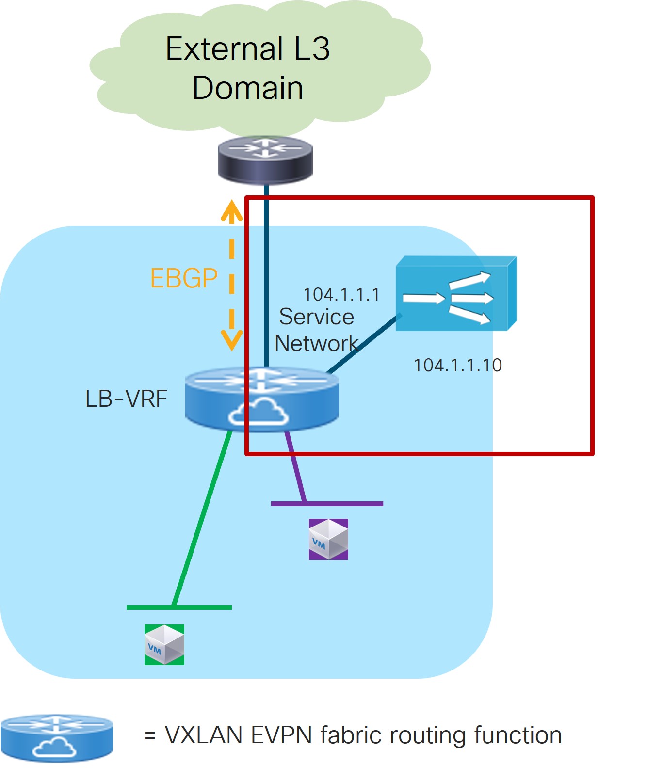
-
In the IPv4 and/or IPv6 field, choose from the following options:
-
IPv4
-
IPv6
-
IPv4 and IPv6
In our example, we will be choosing IPv4.
-
-
Enter the necessary information in this window to complete the configuration of the service cluster logical connectivity.
The remaining fields in this window vary depending on the connectivity mode that you chose. For this example, if Two Arms was automatically selected based on the service insertion use case that you choose for this use case, the following fields would appear:
Field
Description
Service IPv4
Enter the firewall’s IPv4 and/or IPv6 service address.
For example, for this use case’s example configuration figure shown at the beginning of this section, you would enter
10.102.102.1in this field.Service IPv6
Service Network
Choose an existing service network to associate with this service function, or click +Add Service Network to create a new service network. Refer to the section "Networks" in About Fabric Overview for LAN Operational Mode Setups for more information.
If you were creating a new service network, for this use case’s example configuration figure shown at the beginning of this section, you would enter
10.102.102.254/24in the IPv4 Anycast Gateway/Netmask field. This value would appear in the Gateway IP field in the Service Network area in the Add Service Cluster Logical Connectivity window in this case.Probe
Choose an existing probe to associate with this service function, or click +Add Probe to create a new probe.
For this use case, we will click +Add Probe to add a probe configuration. Go to 5b. Add Probe Configuration (Load Balancer).
5b. Add Probe Configuration (Load Balancer)
-
In the Add Probe Configuration window, enter a name for the probe in the Probe Name field.
-
In the Probe Template field, choose service_endpoint.
-
Enter the necessary information to configure the probe:
Field
Description
General Parameters
Enable Probe
Check the box to enable the probe of the (reversed) next hop address.
Probing is performed from every leaf node in the fabric. The source interface used for probing is a loopback interface defined on each leaf node in the Service VRF. The provisioning of those loopbacks mandate to set the Per VRF Per VTEP Loopback IPv4 Auto-Provisioning and Per VRF Per VTEP Loopback IPv6 Auto-Provisioning fields under Resources for that fabric. Refer to Data Center VXLAN EVPN for more information.
When enabling the “Per VRF Per VTEP Loopback” options above, loopback addresses will be assigned to each VTEP for all the VRFs that are locally defined. The IP addresses to be assigned for those loopback addresses are taken from a global pool specified at the fabric level. In the NDFC 12.2.2 release, it is permitted to assign overlapping IP addresses to loopback addresses assigned to different VTEPs in different VRFs. This could create issues when VRF leaking is configured between the tenant VRF(s) and the Service-FW and Service-LB VRFs. We therefore strongly recommend that you manually assign those loopback addresses (it can be done at the VRF level for each VTEP in the fabric) to ensure their uniqueness inside and across the defined VRFs.
Protocol
Specify the protocol to be used for the probe. Options are:
-
icmp
-
tcp
-
udp
-
http
Port Number
Displayed for input only if the protocol is tcp or udp. Enter the port number for the probe. Valid ranges: 1-65535 (recommended range:1025-65534).
User Input for HTTP Probe
Displayed for input only if the protocol is http. Enter a user input text/filename for an HTTP probe (for example: http://192.168.50.254/index.html). Maximum size: 99.
Advanced
Threshold
Enter the threshold value, in seconds. Valid range: 1 - 60.
Frequency
Enter the frequency value in seconds. Valid range: 1 - 604800.
Delay Down Change Notification
Enter the delay down change notification value, in seconds. Valid range: 1 - 180.
Delay Up Change Notification
Enter the delay up change notification value, in seconds. Valid range: 1 - 180.
Timeout
Enter the timeout value, in seconds. Valid range: 1 - 604800.
For more information on the configuration of probes for service redirection, refer to the NX-OS configuration guide.
-
-
Continue to 4c. Add Service Cluster Logical Connectivity (Load Balancer).
4c. Add Service Cluster Logical Connectivity (Load Balancer)
-
In the Peering Option field, choose the appropriate peering option to associate with this service function.
The specific option to choose mostly depends on the VIP configuration of the load balancer:
-
If the VIP is part of the previously created LB-Service-Network that is used to connect the One Arm of the load balancer to the fabric, choose Connected as the peering option.
-
If the VIP is part of a different subnet, you can either select the Static or eBGP options to ensure that the fabric knows how to reach that VIP destination.
-
-
Continue to 2c. Select the Probe Fail Action (Load Balancer).
2c. Select the Probe Fail Action (Load Balancer)
-
In the Probe Fail Action field in the Add Service Chain window, select the appropriate probe fail action.
Options are:
-
Forward: Default option where traffic should use the regular routing tables.
-
Drop: Traffic is dropped when service becomes unreachable.
-
Bypass: Traffic is redirected to the next service sequence when there is a failure of the current sequence.
-
None
-
-
Click the check mark to accept the values for the load balancer service chain entry.
-
Click Save.
You are returned to the Add Service Insertion window.
-
Continue to 2d. Create/Select the Source and Destination Networks.
2d. Create/Select the Source and Destination Networks
As the result of the access control list created in step 2a, the matching source and destination networks part of the Source and Destination VRFs that you configured in step 1a are going to be pre-populated in the Networks area. Those entries are needed to indicate to NDFC the interfaces that need to have the ePBR policy applied. Normally, there should be no need to modify those entries, except for the specific case where the source or the destination networks are configured with the any keyword (note that it is not possible to use any in the same entry both as source and destination networks).
The use of any as the source or destination networks represents your intent to specify prefixes that are external to the fabric. A rule using any as the source means that the source of the flow is a client connected to the external network domain. Conversly, a rule using any as the destination means that the destination of the flow is a client that is external to the fabric. Since the external network domain must be reachable through border leaf nodes, the UI mandates that you must specify the interfaces of the border leaf nodes that are used to connect to the external domain for the source (or destination) any network.
For the specific use case of a firewall-load balancer service chain, the configured ACL usually has two entries:
-
The first one is used to match traffic that is sourced from the client network (could be
anyif the clients are externally connected) and destined to the load balancer VIP address (172.16.100.100/32 in this example). -
The second entry is used to match return traffic that is sourced from the server farm and destined to the clients.
The figure below shows the networks entries that are automatically created because of the ACL configuration.

Before proceeding, you must manually delete the specific entry having the VIP subnet as the destination network. This is because the VIP is part of the Service-LB VRF and not the Tenant VRF, so that destination would otherwise be interpreted as an external destination. In any case, you need to apply the ePBR policy only on the interfaces in the tenant VRF, so the only entry that is required is the one with the source network (clients) and the destination network (server farm).
You are returned to the Fabric Overview page, with Services > Service Insertions selected.
Attach and Deploy the Use Case
NDFC 12.2.2 displays an error if the Service VRFs that are associated to each Service Function are not deployed on the compute leaf nodes. Therefore, you must deploy the Service VRFs to the compute leaf nodes before moving to step 1 below.
-
Check the box next to the new service insertion and click the lower (white) Actions dropdown, then select Attach.
After several seconds, the value shown in the Attached column changes to True.
-
Click the upper (blue) Actions dropdown, then select Recalculate and Deploy.
The new configurations are now deployed to the service leaf nodes.
Generic One-Arm Service Function Use Case
The previous sections covered the specific use cases (Service Function as Default Gateway, Service Function as Perimeter Device and Redirection to Service Chain) that can be provisioned with NDFC 12.2.2.
The sections below provide information on other specific scenarios that have the common characteristics of requiring the deployment of a service function in one-arm mode, with the capability of establishing static or eBGP peering with a VRF defined in the fabric.
While the provisioning of this generic one-arm use case is not explicitly supported through the NDFC 12.2.2 GUI, you can easily solve this current limitation by leveraging the Service Function as Default Gateway use case, as highlighted in Figure 28 below.
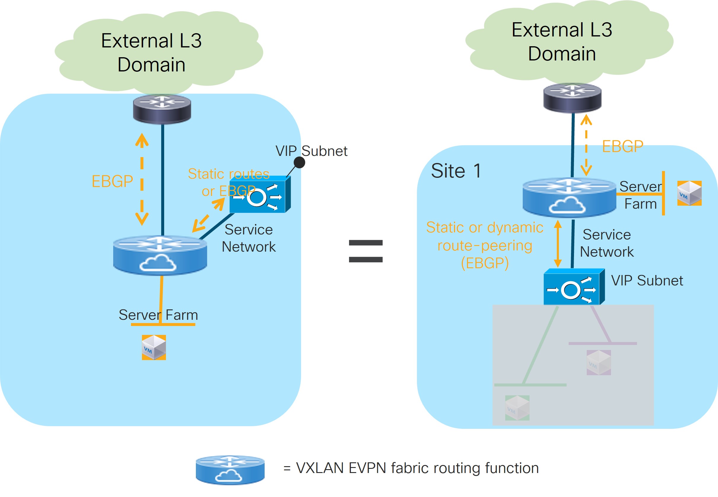
The only difference between provisioning the service function as default-gateway and the service function connected in one-arm to peer with the fabric are the deployment mode and Layer 2 only VNIs. The former needs to be defined as N-Arm deployment mode whereas the latter has One-Arm deployment mode.
With NDFC 12.2.2, you must define at least one Layer 2-only VNI when provisioning the Service as Default-Gateway use case. If your goal is to deploy the service function in one-arm mode peering with the fabric, then you must deploy at least one “dummy” Layer 2-only VNI to satisfy the provisioning workflow.
Refer to the Use Case 1: Service Function as Default Gateway section for the specific provisioning steps. The sections below describe some use cases that require the deployment of the service function in one-arm mode and peering with the fabric (though the information provided below is not exhaustive).
Load Balancer with Source NAT (SNAT)
Refer to the figure below for an example of the Load Balancer with Source NAT (SNAT) use case.
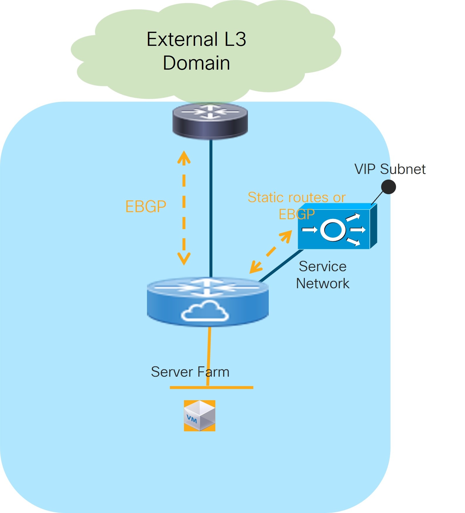
The load balancer is connected in one-arm mode and peers with the fabric (statically or using EBGP) through an interface part of the “Service Network”. This is done to provide access to the VIP address into the fabric so that clients can connect to it.
In the scenario where the VIP address is part of the subnet associated to the “Service Network”, the design gets simplified as no static or dynamic routing is required between the load balancer and the fabric, and you can simply connect the load balancer to the “Service Network” as if it was a regular endpoint.
Once the load balancer receives the traffic originated by the clients, it performs both SNAT and DNAT and forwards the traffic toward the server farm. The return traffic originated from the server farm is hence automatically steered back to the load balancer (without requiring any service redirection functionality on the fabric) as destined to a specific load balancer IP address. The load balancer performs then SNAT and DNAT and sends the traffic back to the clients.
One Arm Perimeter Firewall
This scenario is shown in Figure 30 and represents a variation of the use case previously discussed in the Use Case 2: Service Function as Perimeter Device section.
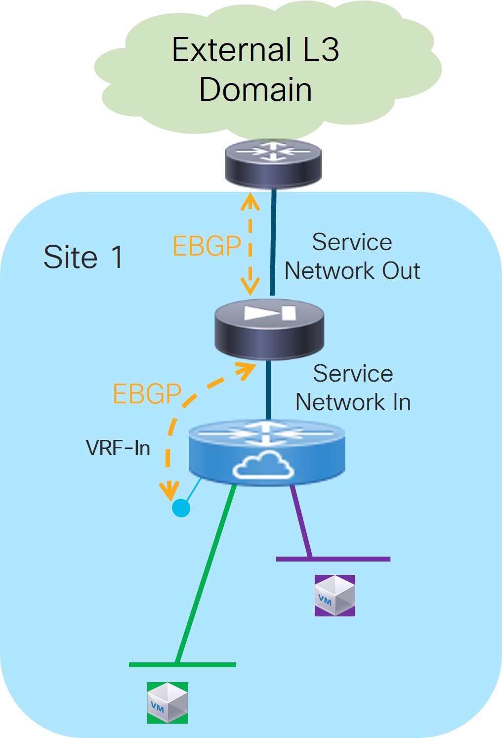
The only difference is that the firewall in this case is peering northbound directly with an external router (and not with a VRF defined in the fabric). Therefore, the workflow described for Use Case 2 cannot be applied here.
The firewall can connect northbound to the external routers in two different ways. The first is by using dedicated physical interfaces, while the second is by using the fabric as a Layer 2 transport to establish the routing peering with the external routers. In the second scenario, you would have to provision a Layer 2 only VNI separately in the fabric to connect the firewall nodes and the external routers.
You can also leverage the same One Arm Perimeter Firewall scenario in a multi-tenant fabric deployment, where the firewall node acts as the “fusion device” between different tenants’ VRFs, ensuring policy enforcement for traffic flows between different tenants and for traffic flows between each tenant and the external network domain (Figure 31).
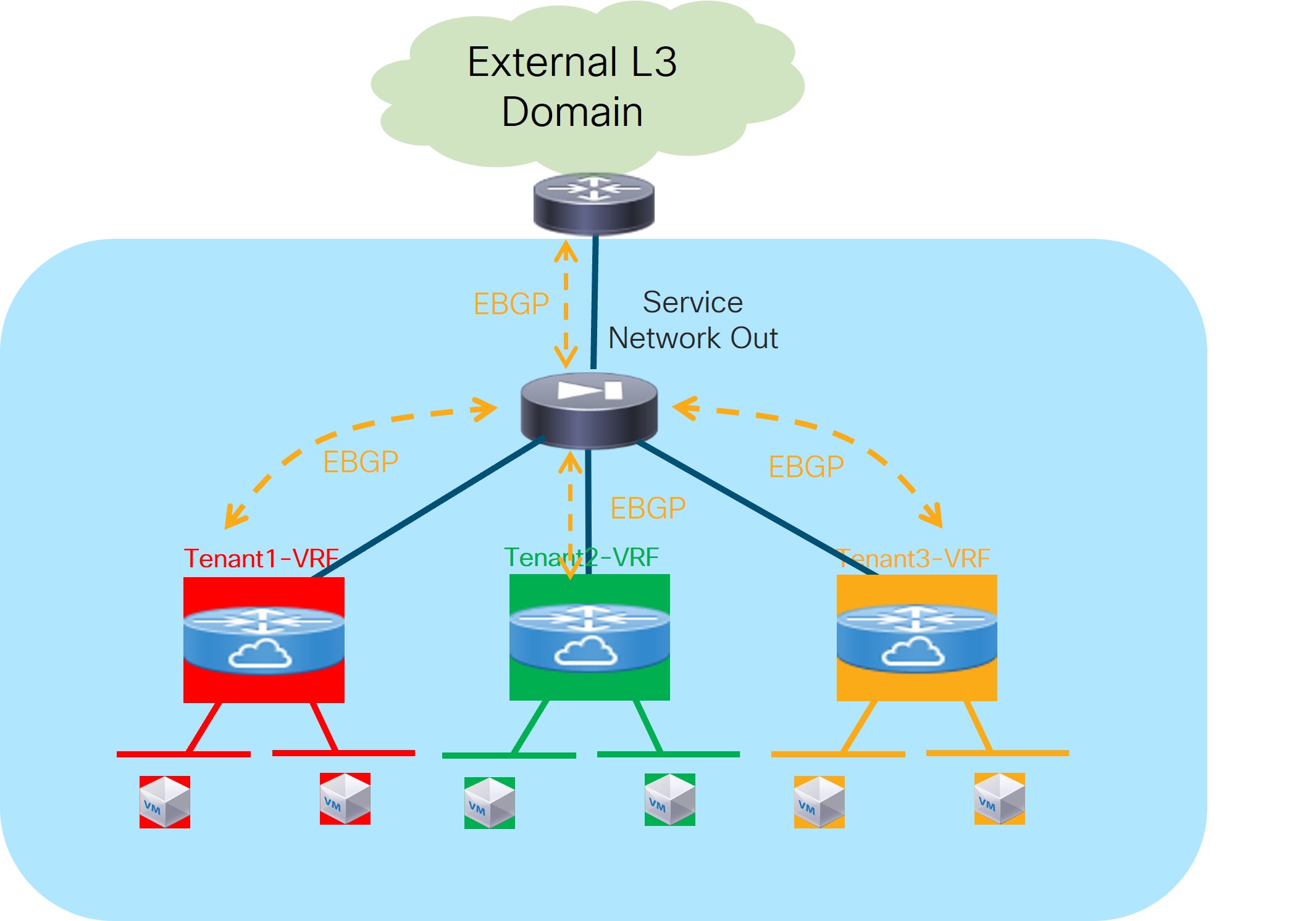
Since all the VRFs are defined on the same fabric, they inherit the BGP ASN of the fabric by default. Therefore, to ensure a successful exchange of prefixes between tenants (through the firewall), we recommend that you use the “local-AS” configuration on each VRF to ensure that they all expose unique BGP ASNs. You can access this setting in the Advanced area when you configure the eBGP peering between the service function and the fabric.
In this specific scenario, the same firewall cluster is used in the workflows required for the attachment of the service function to each tenant VRF. This is because different interfaces of the same firewall device are assigned to different tenants. A possible alternative scenario, shown in Figure 32, consists in having a firewall cluster dedicated per tenant.
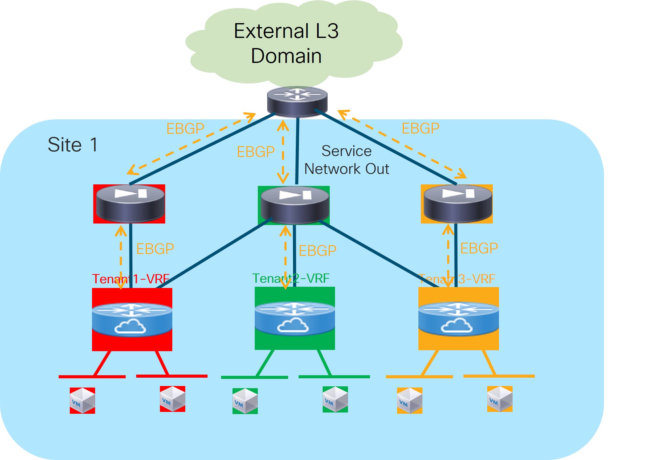
Copyright
THE SPECIFICATIONS AND INFORMATION REGARDING THE PRODUCTS IN THIS MANUAL ARE SUBJECT TO CHANGE WITHOUT NOTICE. ALL STATEMENTS, INFORMATION, AND RECOMMENDATIONS IN THIS MANUAL ARE BELIEVED TO BE ACCURATE BUT ARE PRESENTED WITHOUT WARRANTY OF ANY KIND, EXPRESS OR IMPLIED. USERS MUST TAKE FULL RESPONSIBILITY FOR THEIR APPLICATION OF ANY PRODUCTS.
THE SOFTWARE LICENSE AND LIMITED WARRANTY FOR THE ACCOMPANYING PRODUCT ARE SET FORTH IN THE INFORMATION PACKET THAT SHIPPED WITH THE PRODUCT AND ARE INCORPORATED HEREIN BY THIS REFERENCE. IF YOU ARE UNABLE TO LOCATE THE SOFTWARE LICENSE OR LIMITED WARRANTY, CONTACT YOUR CISCO REPRESENTATIVE FOR A COPY.
The Cisco implementation of TCP header compression is an adaptation of a program developed by the University of California, Berkeley (UCB) as part of UCB’s public domain version of the UNIX operating system. All rights reserved. Copyright © 1981, Regents of the University of California.
NOTWITHSTANDING ANY OTHER WARRANTY HEREIN, ALL DOCUMENT FILES AND SOFTWARE OF THESE SUPPLIERS ARE PROVIDED “AS IS" WITH ALL FAULTS. CISCO AND THE ABOVE-NAMED SUPPLIERS DISCLAIM ALL WARRANTIES, EXPRESSED OR IMPLIED, INCLUDING, WITHOUT LIMITATION, THOSE OF MERCHANTABILITY, FITNESS FOR A PARTICULAR PURPOSE AND NONINFRINGEMENT OR ARISING FROM A COURSE OF DEALING, USAGE, OR TRADE PRACTICE.
IN NO EVENT SHALL CISCO OR ITS SUPPLIERS BE LIABLE FOR ANY INDIRECT, SPECIAL, CONSEQUENTIAL, OR INCIDENTAL DAMAGES, INCLUDING, WITHOUT LIMITATION, LOST PROFITS OR LOSS OR DAMAGE TO DATA ARISING OUT OF THE USE OR INABILITY TO USE THIS MANUAL, EVEN IF CISCO OR ITS SUPPLIERS HAVE BEEN ADVISED OF THE POSSIBILITY OF SUCH DAMAGES.
Any Internet Protocol (IP) addresses and phone numbers used in this document are not intended to be actual addresses and phone numbers. Any examples, command display output, network topology diagrams, and other figures included in the document are shown for illustrative purposes only. Any use of actual IP addresses or phone numbers in illustrative content is unintentional and coincidental.
The documentation set for this product strives to use bias-free language. For the purposes of this documentation set, bias-free is defined as language that does not imply discrimination based on age, disability, gender, racial identity, ethnic identity, sexual orientation, socioeconomic status, and intersectionality. Exceptions may be present in the documentation due to language that is hardcoded in the user interfaces of the product software, language used based on RFP documentation, or language that is used by a referenced third-party product.
Cisco and the Cisco logo are trademarks or registered trademarks of Cisco and/or its affiliates in the U.S. and other countries. To view a list of Cisco trademarks, go to this URL: https://www.cisco.com/go/trademarks. Third-party trademarks mentioned are the property of their respective owners. The use of the word partner does not imply a partnership relationship between Cisco and any other company. (1110R)
© 2017-2025 Cisco Systems, Inc. All rights reserved.