- Title and copyright: PA-MC-2T3+ Multi-Channel T3 Port Adapter Installation and Configuration
- Preface: PA-MC-2T3+ Multi-Channel T3 Port Adapter Installation and Configuration
- Overview: PA-MC-2T3+ Multi-Channel T3 Port Adapter Installation and Configuration
- Preparing to Install the PA-MC-2T3+ Multi-Channel T3 Port Adapter
- Removing and Installing the PA-MC-2T3+ Multi-Channel T3 Port Adapter
- Configuring Unchannelized Mode for the PA-MC-2T3+ Multi-Channel T3 Port Adapter
- Configuring Channelized Mode for the PA-MC-2T3+ Multi-Channel T3 Port Adapter
PA-MC-2T3+ Multichannel T3 Port Adapter Installation and Configuration
Bias-Free Language
The documentation set for this product strives to use bias-free language. For the purposes of this documentation set, bias-free is defined as language that does not imply discrimination based on age, disability, gender, racial identity, ethnic identity, sexual orientation, socioeconomic status, and intersectionality. Exceptions may be present in the documentation due to language that is hardcoded in the user interfaces of the product software, language used based on RFP documentation, or language that is used by a referenced third-party product. Learn more about how Cisco is using Inclusive Language.
- Updated:
- September 14, 2007
Chapter: Overview: PA-MC-2T3+ Multi-Channel T3 Port Adapter Installation and Configuration
Overview
This chapter describes the Cisco PA-MC-2T3+ port adapter and contains the following sections:
•![]() LEDs
LEDs
•![]() Port Adapter Slot Locations on the Supported Platforms
Port Adapter Slot Locations on the Supported Platforms
•![]() Identifying Interface Addresses
Identifying Interface Addresses
Port Adapter Overview
The PA-MC-2T3+ is a single-width port adapter that provides two T3 interface connections using BNC connectors. (See Figure 1-1.) Each T3 interface can be independently configured to be either channelized or unchannelized. A channelized T3 provides 28 T1 lines multiplexed into the T3. Each T1 line can be configured into one or more serial interface data channels.
An unchannelized T3 provides a single serial interface data channel that may be configured to use all of the T3 bandwidth or a fractional portion of it. This mode is compatible with several vendors of fractional (subrate) DS3 data service units (DSUs).
Figure 1-1 PA-MC-2T3+—Front Panel

The PA-MC-2T3+ has the following features and physical characteristics:
•![]() The PA-MC-2T3+ supports both channelized and unchannelized operations.
The PA-MC-2T3+ supports both channelized and unchannelized operations.
•![]() It transmits and receives data bidirectionally at the T3 rate of 44.736 Mbps.
It transmits and receives data bidirectionally at the T3 rate of 44.736 Mbps.
•![]() It conforms to relevant specifications for DS3 (Digital Signal Level 3) circuits.
It conforms to relevant specifications for DS3 (Digital Signal Level 3) circuits.
•![]() The T3 connection, provided by two female BNC connectors for transmit (TX) and receive (RX), requires 734A coaxial cable that has an impedance of 75 ohms.
The T3 connection, provided by two female BNC connectors for transmit (TX) and receive (RX), requires 734A coaxial cable that has an impedance of 75 ohms.
•![]() It supports RFC 1406 and RFC 1407 (CISCO-RFC-1407-CAPABILITY.my). For RFC 1406, Cisco supports all tables except the FarEnd table. For RFC 1407, Cisco does not support FarEnd or Fractional tables. (For information on accessing Cisco MIB files, refer to the Cisco MIB User Quick Reference publication.)
It supports RFC 1406 and RFC 1407 (CISCO-RFC-1407-CAPABILITY.my). For RFC 1406, Cisco supports all tables except the FarEnd table. For RFC 1407, Cisco does not support FarEnd or Fractional tables. (For information on accessing Cisco MIB files, refer to the Cisco MIB User Quick Reference publication.)
•![]() PA-MC-2T3+ microcode is loaded at initialization and is bundled into IOS software.
PA-MC-2T3+ microcode is loaded at initialization and is bundled into IOS software.
Channelized T3 Overview
In the channelized mode of operation, a PA-MC-2T3+ T3 link is channelized into 28 DS1 data lines in an industry standard multiplexing format.
Each of the T1 lines contains 24 timeslots of 64 or 56 kbps each. The T1 lines can support one or more user data channels which appear to the system as serial interfaces. Each serial interface is assigned one or more of the timeslots giving the serial interface a bandwidth of n x 56 kbps or n x 64 kbps, where n is the number of timeslots assigned. Any unused timeslots of the T1 are filled with an idle channel pattern.
The following restrictions apply: A timeslot can only be used by one serial interface. A serial interface cannot use timeslots from more than one T1 line. Each T3 can have a maximum of 128 serial interfaces. Unused serial interfaces on one T3 cannot be used by the other T3.
The PA-MC-2T3+ supports Cisco High-Level Data Link Control (HDLC), Frame Relay, PPP, and Switched Multimegabit Data Service (SMDS) Data Exchange Interface (DXI) encapsulations over each serial interface.

Note ![]() T1 lines on the PA-MC-2T3+ are numbered 1-28, rather than the more traditional zero-based scheme (0-27) used with other Cisco products. This is to ensure consistency with telco numbering schemes for T1 lines within channelized T3 equipment.
T1 lines on the PA-MC-2T3+ are numbered 1-28, rather than the more traditional zero-based scheme (0-27) used with other Cisco products. This is to ensure consistency with telco numbering schemes for T1 lines within channelized T3 equipment.
Note ![]() The PA-MC-2T3+ does not support the aggregation of multiple T1 lines (called inverse multiplexing or bonding) in hardware for higher bandwidth data rates. MLPPP may be used for this purpose in software.
The PA-MC-2T3+ does not support the aggregation of multiple T1 lines (called inverse multiplexing or bonding) in hardware for higher bandwidth data rates. MLPPP may be used for this purpose in software.
The T3 section of the PA-MC-2T3+ supports the maintenance data-link channel (MDL) when using c-bit parity framing as well as local and network loopbacks. The T1 section of the PA-MC-2T3+ supports facilities data link (FDL) in Extended Superframe (ESF) framing, as well as various loopbacks. Bit error rate testing (BERT) is supported on each of the T1 lines although a test may not be active on more than one T1 at a time. BER testing may be done over a framed or unframed T1 signal.
Unchannelized T3 Overview
In the unchannelized mode of operation, a T3 link provides a single high speed user data channel, rather than being multiplexed into 28 T1 lines. The data channel appears to the system as a serial interface that may be configured to use the full T3 bandwidth or a smaller portion of the T3 bandwidth. No industry standard exists for subdividing the T3 bandwidth but the PA-MC-2T3+ is compatible with the proprietary formats of five vendors of T3 DSUs, when used at the far end of the T3 link.
In unchannelized T3 mode, the T3 section supports the maintenance data link (MDL) channel when using c-bit parity framing as well as local and network loopbacks. Bit error rate testing (BERT) is supported on the T3 link. The PA-MC-2T3+ supports Cisco High-Level Data Link Control (HDLC), Frame Relay, PPP, and Switched Multimegabit Data Service (SMDS) Data Exchange Interface (DXI) encapsulations over the serial interface.
T3 Specifications
The PA-MC-2T3+ T3 port is designed to receive and transmit at the DSX-3 level while driving and receiving from 75-ohm coaxial cables (ATT 734A or equivalent quality coax). The T3 port connects directly to any equipment with DSX-3 level BNC connectors.
Table 1-1 lists the specifications that the T3 front end is designed to meet.
Note ![]() The coax shield side of the T3 BNC connectors is connected to the router chassis ground.
The coax shield side of the T3 BNC connectors is connected to the router chassis ground.
Unchannelized Interoperability Guidelines for DSUs
The PA-MC-2T3+ supports several types of integrated data service units (DSUs). Table 1-2 lists the feature compatibilities of PA-MC-2T3+ DSUs.
Note ![]() The PA-MC-2T3+ does not support configuration of the far end T3 DSU using the maintenance data link channel in c-bit parity framing.
The PA-MC-2T3+ does not support configuration of the far end T3 DSU using the maintenance data link channel in c-bit parity framing.
LEDs
The PA-MC-2T3+ has seven status LEDs located on its faceplate: ENABLED, ALARM, LOOP, LOS, OOF, AIS, and FERF. (These status LEDs are shown from left to right in Figure 1-2.)
Figure 1-2 PA-MC-2T3+ Status LEDs—Partial Horizontal View

After system initialization, the green ENABLED LED indicates that the port adapter is enabled for operation.
The following conditions must be met before the PA-MC-2T3+ is enabled:
•![]() The port adapter is correctly installed in the VIP motherboard or Cisco 7200 series router slot and is receiving power.
The port adapter is correctly installed in the VIP motherboard or Cisco 7200 series router slot and is receiving power.
•![]() The system software recognizes the PA-MC-2T3+
The system software recognizes the PA-MC-2T3+
If either one of the preceding conditions is not met, or if the initialization fails for other reasons, the enabled LED does not go on.
Table 1-3 lists LED colors and indications.
In addition to the interface status information provided by the LEDs, you can also retrieve detailed interface status information either through the router console port or through Telnet or Simple Network Management Protocol (SNMP).
Port Adapter Slot Locations on the Supported Platforms
This section discusses port adapter slot locations on the supported platforms. The illustrations that follow summarize slot location conventions on each platform:
•![]() Cisco 7200 Series Routers Slot Numbering
Cisco 7200 Series Routers Slot Numbering
•![]()
•![]() Cisco 7301 Router Slot Numbering
Cisco 7301 Router Slot Numbering
•![]() Cisco 7304 PCI Port Adapter Carrier Card Slot Numbering
Cisco 7304 PCI Port Adapter Carrier Card Slot Numbering
•![]() Cisco 7401ASR Router Slot Numbering
Cisco 7401ASR Router Slot Numbering
Cisco 7200 Series Routers Slot Numbering
Figure 1-4 shows a Cisco 7206 with port adapters installed. In the Cisco 7206 (including the Cisco 7206 and Cisco 7206VXR as router shelves in a Cisco AS5800 Universal Access Server), port adapter slot 1 is in the lower left position, and port adapter slot 6 is in the upper right position. (The Cisco 7202 and Cisco 7204 are not shown; however, the PA-MC-2T3+ can be installed in any available port adapter slot 1 through 6.)
Cisco 7200 VXR Router with the Port Adapter Jacket Card Slot Numbering
Figure 1-3 Port Adapter Slots in Cisco 7206 VXR Router with the Port Adapter Jacket Card

|
|
Slot 5 |
|
Slot 6 |
|
|
Slot 3 |
|
Slot 4 |
|
|
Slot 1 |
|
Slot 2 |
|
|
Slot 7-port adapter (slot 0-Jacket Card) |
Table 1-3 shows the slot number of port adapters in a Cisco 7200 VXR router with the Port Adapter Jacket Card installed. Port adapter slots in the Cisco 7200 VXR routers are numbered from left to right. With an NPE-G1 or NPE-G2 installed, port adapter slot 0 can accept the Port Adapter Jacket Card. The Port Adapter Jacket Card resides in port adapter slot 0. The port adapter in the Port Adapter jacket card resides in port adapter slot 5 on the Cisco 7204 VXR router, or port adapter slot 7 on the Cisco 7206 VXR router.
Figure 1-4 Port Adapter Slots in the Cisco 7206

Cisco 7301 Router Slot Numbering
Figure 1-5 shows the front view of a Cisco 7301 router with a port adapter installed. The Cisco 7301 router has one standard port adapter slot.
Figure 1-5 Port Adapter Slot in the Cisco 7301 Router

Cisco 7304 PCI Port Adapter Carrier Card Slot Numbering
The Cisco 7304 PCI Port Adapter Carrier Card accepts one single-width port adapter. Figure 1-6 shows a Cisco 7304 PCI Port Adapter Carrier Card with a port adapter installed.
Figure 1-6 Cisco 7304 PCI Port Adapter Carrier Card—Port Adapter Installed

The Cisco 7304 PCI Port Adapter Carrier Card installs in Cisco 7304 router module slots 2 through 5. See Figure 1-7 for module slot numbering on a Cisco 7304 router.
Figure 1-7 Module Slots on the Cisco 7304 Router

Cisco 7401ASR Router Slot Numbering
Figure 1-8 shows the front view of a Cisco 7401ASR router with a port adapter installed. There is only one port adapter slot in a Cisco 7401ASR router.
Figure 1-8 Port Adapter Slot in the Cisco 7401ASR Router
VIP Slot Numbering
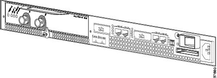
Figure 1-9 shows a partial view of a VIP motherboard with installed port adapters. With the motherboard oriented as shown in Figure 1-9, the left port adapter is in port adapter slot 0, and the right port adapter is in port adapter slot 1.
Figure 1-9 VIP Motherboard with Two Port Adapters Installed—Horizontal Orientation

Note ![]() In the Cisco 7000, Cisco 7507, and Cisco 7513 chassis, the VIP motherboard is installed vertically. In the Cisco 7010 and Cisco 7505 chassis, the VIP motherboard is installed horizontally.
In the Cisco 7000, Cisco 7507, and Cisco 7513 chassis, the VIP motherboard is installed vertically. In the Cisco 7010 and Cisco 7505 chassis, the VIP motherboard is installed horizontally.
Interface processor slots are numbered as shown in Figure 1-10.
Figure 1-10 Interface Slot Numbers—Cisco 7505 Shown

Identifying Interface Addresses
This section describes how to identify interface addresses for the PA-MC-2T3+ in supported platforms. Interface addresses specify the actual physical location of each interface on a router or switch.
Interfaces on the PA-MC-2T3+ installed in a router maintain the same address regardless of whether other port adapters are installed or removed. However, when you move a port adapter to a different slot, the first number in the interface address changes to reflect the new port adapter slot number.
Interfaces on a PA-MC-2T3+ installed in a VIP maintain the same address regardless of whether other interface processors are installed or removed. However, when you move a VIP to a different slot, the interface processor slot number changes to reflect the new interface processor slot.
Note ![]() Interface ports are numbered from left to right starting with 0.
Interface ports are numbered from left to right starting with 0.
Table 1-4 explains how to identify interface addresses.
|
|
|
|
|
|---|---|---|---|
Cisco 7120 series routers |
Port-adapter-slot-number/interface-port-number |
Port adapter slot—always 3 Interface port—0 and 1 |
3/1 |
Cisco 7140 series routers |
Port-adapter-slot-number/interface-port-number |
Port adapter slot—always 4 Interface port—0 and 1 |
4/0 |
Cisco 7200 series routers |
Port-adapter-slot-number/interface-port-number |
Port adapter slot—0 through 6 (depends on the number of slots in the router)1 Interface port—0 and 1 |
1/0 |
Port Adapter Jacket Card with the Cisco 7200 VXR router2 |
Port-adapter-slot-number/interface-port-number |
Port adapter slot—0 through 7 (depends on the number of slots in the router)3 Interface port—0 and 1 |
1/0 |
Cisco 7301 routers |
Port-adapter-slot-number/interface-port-number |
Port adapter slot—always 1 Interface port—0 and 1 |
1/0 |
Cisco 7304 PCI Port Adapter Carrier Card in Cisco 7304 routers |
Port-adapter-slot-number/interface-port-number |
Port adapter slot—router module slot 2 through 5 Interface port—0 and 1 |
3/0 |
Cisco 7401ASR routers |
Port-adapter-slot-number/interface-port-number |
Port adapter slot—always 1 Interface port—0 and 1 |
1/0 |
VIP in Cisco 7000 series or |
Interface-processor-slot-number/port-adapter-slot- |
Interface processor slot—0 through 12 (depends on the number of slots in the router) Port adapter slot—always 0 or 1 Interface port—0 and 1 |
3/1/0 |
1 Port adapter slot 0 is reserved for the Fast Ethernet port on the I/O controller (if present). 2 Port adapter slot 0 can accept the Port Adapter Jacket Card if an NPE-G1 or NPE-G2 are installed. 3 Port adapter slot 0 is reserved for the Fast Ethernet port on the I/O controller (if present). |
Cisco 7200 Series Routers Interface Addresses
This section describes how to identify the interface addresses used for the PA-MC-2T3+ in Cisco 7200 series routers. The interface address is composed of a two-part number in the format port-adapter-slot-number/interface-port-number. See Table 1-4 for the interface address format.
In Cisco 7200 series routers, port adapter slots are numbered from the lower left to the upper right, beginning with port adapter slot 1 and continuing through port adapter slot 2 for the Cisco 7202, slot 4 for the Cisco 7204 and Cisco 7204VXR, and slot 6 for the Cisco 7206 and Cisco 7206VXR. (Port adapter slot 0 is reserved for the optional Fast Ethernet port on the I/O controller—if present.)
The interface addresses of the interfaces on the PA-MC-2T3+ in port adapter slot 1 are 1/0 through 1/1 (port adapter slot 1 and interfaces 0 and 1). If the PA-MC-2T3+ was in port adapter slot 4, these same interfaces would be numbered 4/0 through 4/1 (port adapter slot 4 and interfaces 0 and 1).
Cisco 7301 Router Interface Addresses
This section describes how to identify addresses used for the PA-MC-2T3+ in the Cisco 7301 router. In the Cisco 7301 router, slot 1 is the port adapter slot you use for the PA-MC-2T3+. (See Figure 1-5.)
The interface address is composed of a two-part number in the format port-adapter-slot-number/interface-port-number. See Table 1-4 for the interface address format.
Cisco 7304 PCI Port Adapter Carrier Card Interface Addresses
This section describes how to identify the interface addresses used for the PA-MC-2T3+ in the Cisco 7304 PCI Port Adapter Carrier Card in Cisco 7304 routers. The interface address is made of a two-part number in the format port-adapter-slot-number/interface-port-number.
The Cisco 7304 PCI Port Adapter Carrier Card installs into Cisco 7304 router module slots 2 through 5 (See Figure 1-7.) The port-adapter-slot-number is the Cisco 7304 router module slot number. For example, the interface address of port 0 on a PA-MC-2T3+, in which the Cisco 7304 PCI Port Adapter Carrier Card is installed in Cisco 7304 router module slot 3, would be numbered 3/0.
Cisco 7401ASR Router Interface Addresses
This section describes how to identify addresses used for the PA-MC-2T3+ in the Cisco 7401ASR router. In the Cisco 7401ASR router, slot 1 is the port adapter slot you use for the PA-MC-2T3+.
(See Figure 1-8.) The interface address is composed of a two-part number in the format port-adapter-slot-number/interface-port-number. See Table 1-4 for the interface address format.
VIP Interface Addresses
This section describes how to identify the interface addresses used for the PA-MC-2T3+ on a VIP in Cisco 7000 series and Cisco 7500 series routers.
Note ![]() Although the processor slots in the 7-slot Cisco 7000 and Cisco 7507 and the 13-slot Cisco 7513 and Cisco 7576 are vertically oriented and those in the 5-slot Cisco 7010 and Cisco 7505 are horizontally oriented, all Cisco 7000 series and Cisco 7500 series routers use the same method for slot and port numbering.
Although the processor slots in the 7-slot Cisco 7000 and Cisco 7507 and the 13-slot Cisco 7513 and Cisco 7576 are vertically oriented and those in the 5-slot Cisco 7010 and Cisco 7505 are horizontally oriented, all Cisco 7000 series and Cisco 7500 series routers use the same method for slot and port numbering.
See Table 1-4 for the interface address format. The interface address is composed of a three-part number in the format interface-processor-slot-number/port-adapter-slot-number/interface-port-number.
If the VIP is inserted in interface processor slot 3, then the interface addresses of the PA-MC-2T3+ are 3/1/0 through 3/1/1 (interface processor slot 3, port adapter slot 1, and interfaces 0 and 1). If the port adapter was in port adapter slot 0 on the VIP, these same interface addresses would be numbered 3/0/0 through 3/0/1.
Note ![]() If you remove the VIP with the PA-MC-2T3+ (shown in Figure 1-9) from interface processor slot 3 and install it in interface processor slot 2, the interface addresses become 2/1/0 through 2/1/1.
If you remove the VIP with the PA-MC-2T3+ (shown in Figure 1-9) from interface processor slot 3 and install it in interface processor slot 2, the interface addresses become 2/1/0 through 2/1/1.
 Feedback