- Preface
- Product Overiew
- Networking with the Content Switching Module
- Getting Started
- Configuring VLANs
- Configuring Real Servers and Server Farms
- Configuring Virtual Servers, Maps, and Policies
- Configuring Redundant Connections
- Configuring Additional Features and Options
- Configuring Health Monitoring
- Configuring CSM Scripts
- Configuring Firewall Load Balancing
- Configuration Examples
- Troubleshooting and System Messages
- CSM XML Document Type Definition
Catalyst 6500 Series Switch Content Switching Module Installation and Configuration Note Software Release 4.1.x
Bias-Free Language
The documentation set for this product strives to use bias-free language. For the purposes of this documentation set, bias-free is defined as language that does not imply discrimination based on age, disability, gender, racial identity, ethnic identity, sexual orientation, socioeconomic status, and intersectionality. Exceptions may be present in the documentation due to language that is hardcoded in the user interfaces of the product software, language used based on RFP documentation, or language that is used by a referenced third-party product. Learn more about how Cisco is using Inclusive Language.
- Updated:
- March 18, 2015
Chapter: Networking with the Content Switching Module
Networking with the Content Switching Module
This chapter describes networking the CSM and contains these sections:
•![]() Configuring Modes for Networking
Configuring Modes for Networking
•![]() Protecting Against Denial-of-Service Attacks
Protecting Against Denial-of-Service Attacks
Configuring Modes for Networking
You can configure the CSM in a secure or router mode and a single subnet or bridged mode. These sections describe the modes:
•![]() Configuring the Secure (Router) Mode
Configuring the Secure (Router) Mode
•![]() Configuring the Single Subnet (Bridge) Mode
Configuring the Single Subnet (Bridge) Mode
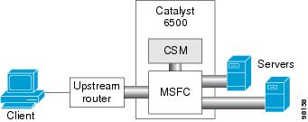
Configuring the Secure (Router) Mode
In secure (router) mode, the client-side and server-side VLANs are on different subnets. Figure 2-1 shows how the secure (router) mode configuration is set up.
Figure 2-1 Secure (Router) Mode Configuration


Note ![]() The addresses in Figure 2-1 refer to the steps in the following task table.
The addresses in Figure 2-1 refer to the steps in the following task table.
To configure content switching in secure (router) mode, perform this task:
|
|
|
|
|---|---|---|
Step 1 |
Router(config-module-csm)# vlan database
|
Enters the VLAN mode1 . |
Step 2 |
Router(vlan)# vlan 2 |
Configures a client-side VLAN2 . |
Step 3 |
Router(vlan)# vlan 3 |
Configures a server-side VLAN. |
Step 4 |
Router(vlan)# exit |
Exits the mode for the configuration to take effect. |
Step 5 |
Router(config-module-csm)# vlan 2 client
|
Creates the client-side VLAN 2 and enters the SLB VLAN mode. |
Step 6 |
Router(config-slb-vlan-client)# ip addr
192.158.38.10 255.255.255.0
|
Assigns the CSM IP address on VLAN 2. |
Step 7 |
Router(config-slb-vlan-client)# gateway
192.158.38.20
|
Defines the client-side VLAN gateway to Router A. |
Step 8 |
Router(config-slb-vlan-client)# gateway
192.158.38.21
|
Defines the client-side VLAN gateway to Router B. |
Step 9 |
Router(config-module-csm)# vlan 3 server
|
Creates the server-side VLAN 3 and enters the SLB VLAN mode. |
Step 10 |
Router(config-slb-vlan-server)# ip addr
192.158.39.10 255.255.255.0
|
Assigns the CSM IP address on VLAN 3. |
Step 11 |
Router(config-slb-vlan-server)# exit
|
Exits the submode. |
Step 12 |
Router(config-module-csm)# vserver VIP1
|
Creates a virtual server and enters the SLB virtual server mode. |
Step 13 |
Router(config-slb-vserver)# virtual
192.158.38.30 tcp www
|
Creates a virtual IP address. |
Step 14 |
Router(config-slb-vserver)# serverfarm farm1 |
Associates the virtual server with the server farm3 . |
Step 15 |
Router(config-module-csm)# inservice |
Enables the server. |
1 Enter the exit command to leave a mode or submode. Enter the end command to return to the menu's-top level. 2 The no form of this command restores the defaults. 3 This step assumes that the server farm has already been configured. (See the "Configuring Server Farms" section on page 5-1.) |
Note ![]() Set the server default routes to the IP address on the CSM (192.158.39.10).
Set the server default routes to the IP address on the CSM (192.158.39.10).
Configuring the Single Subnet (Bridge) Mode
In the single subnet (bridge) mode configuration, the client-side and server-side VLANs are on the same subnets. You configure single subnet (bridge) mode by assigning the same IP address to the CSM client and server VLANs.
Note ![]() The addresses in Figure 2-1 refer to the steps in the following task table, with the exception of setting the server-side IP address to the same value as the client-side IP address.
The addresses in Figure 2-1 refer to the steps in the following task table, with the exception of setting the server-side IP address to the same value as the client-side IP address.
To configure content switching for the single subnet (bridge) mode, perform this task:
|
|
|
|
|---|---|---|
Step 1 |
Router(config-module-csm)# vlan
database
|
Enters the VLAN mode1 . |
Step 2 |
Router(vlan)# vlan 2 |
Configures a client-side VLAN2 . |
Step 3 |
Router(vlan)# vlan 3 |
Configures a server-side VLAN. |
Step 4 |
Router(vlan)# exit |
Exits the mode for the configuration to take effect. |
Step 5 |
Router(config-module-csm)# vlan 2
client
|
Creates the client-side VLAN 2 and enters the SLB VLAN mode1. |
Step 6 |
Router(config-slb-vlan-client)# ip
addr 192.158.38.10 255.255.255.0
|
Assigns the CSM IP address on VLAN 2. |
Step 7 |
Router(config-slb-vlan-client)#
gateway 192.158.38.20
|
Defines the client-side VLAN gateway to Router A. |
Step 8 |
Router(config-slb-vlan-client)#
gateway 192.158.38.21
|
Defines the client-side VLAN gateway to Router B. |
Step 9 |
Router(config-slb-vserver)# vlan 3
server
|
Creates the server-side VLAN 3 and enters the SLB VLAN mode. |
Step 10 |
Router(config-slb-vlan-client)# ip
addr 192.158.38.10 255.255.255.0
|
Assigns the CSM IP address on VLAN 3. |
Step 11 |
Router(config-slb-vlan-server)# exit
|
Exits the submode. |
Step 12 |
Router(config-module-csm)# vserver
VIP1
|
Creates a virtual server and enters the SLB virtual server mode. |
Step 13 |
Router(config-slb-vserver)# virtual
192.158.38.30 tcp www
|
Creates a virtual IP address. |
Step 14 |
Router(config-slb-vserver)# serverfarm farm1 |
Associates the virtual server with the server farm3 . |
Step 15 |
Router(config-module-csm)# inservice |
Enables the server. |
1 Enter the exit command to leave a mode or submode. Enter the end command to return to the menu's-top level. 2 The no form of this command restores the defaults. 3 This step assumes that the server farm has already been configured. (See the "Configuring Server Farms" section on page 5-1.) |
Note ![]() Set the server default routes to the Router A gateway (192.158.38.20) or the Router B gateway (192.158.38.21).
Set the server default routes to the Router A gateway (192.158.38.20) or the Router B gateway (192.158.38.21).
CSM Networking Topologies
This section describes CSM networking topologies and contains these sections:
•![]() CSM Inline and MSFC Not Involved
CSM Inline and MSFC Not Involved
•![]() CSM Inline and MSFC on Server Side
CSM Inline and MSFC on Server Side
•![]() CSM Inline and MSFC on Client Side
CSM Inline and MSFC on Client Side
CSM Inline and MSFC Not Involved
Figure 2-2 shows the CSM in a Layer 3 configuration without interaction with the MSFC.
Figure 2-2 CSM Inline, MSFC Not Involved

This configuration has these characteristics:
•![]() The MSFC is not routing CSM VLANs.
The MSFC is not routing CSM VLANs.
•![]() All server-to-server communications (direct Layer 3 or load balanced) are through the CSM.
All server-to-server communications (direct Layer 3 or load balanced) are through the CSM.
•![]() The CSM must use static routes to the upstream router (default gateway).
The CSM must use static routes to the upstream router (default gateway).
CSM Inline and MSFC on Server Side
Figure 2-3 shows the CSM in a configuration where the MSFC is located on the server side.
Figure 2-3 CSM Inline, MSFC Located on Server Side

This configuration has these characteristics:
•![]() Server-to-server direct communications bypass the CSM.
Server-to-server direct communications bypass the CSM.
•![]() Server-to-server load-balanced connections always require secure NAT (SNAT).
Server-to-server load-balanced connections always require secure NAT (SNAT).
•![]() The CSM must use static routes to the upstream router (default gateway).
The CSM must use static routes to the upstream router (default gateway).
•![]() Routing protocols can be used in the back end.
Routing protocols can be used in the back end.
•![]() Layer 2-rewrite is not possible.
Layer 2-rewrite is not possible.
CSM Inline and MSFC on Client Side
Figure 2-4 shows the CSM in a configuration where the MSFC is located on the client side.
Figure 2-4 CSM Inline, MSFC Located on the Client Side

This configuration has these characteristics:
•![]() The configuration is easy to deploy.
The configuration is easy to deploy.
•![]() Server-to-server Layer 3 communications pass through the CSM.
Server-to-server Layer 3 communications pass through the CSM.
•![]() Routing protocols can be used between the MSFC and the upstream router.
Routing protocols can be used between the MSFC and the upstream router.
•![]() All traffic to or from the servers passes through the CSM.
All traffic to or from the servers passes through the CSM.
CSM in Aggregate Mode
Figure 2-5 shows the CSM in an aggregate-mode configuration.
Figure 2-5 CSM Located in Aggregate Mode
This configuration has these characteristics:
•![]() The CSM is not inline and the module does not see unnecessary traffic.
The CSM is not inline and the module does not see unnecessary traffic.
•![]() Easy routing and CSM configuration.
Easy routing and CSM configuration.
•![]() Requires PBR or client SNAT because return traffic is required.
Requires PBR or client SNAT because return traffic is required.
•![]() Server-to-server load-balanced connections always require SNAT.
Server-to-server load-balanced connections always require SNAT.
•![]() Layer 2-rewrite is not possible.
Layer 2-rewrite is not possible.
Direct Server Return
Figure 2-6 shows the CSM in a direct server return configuration.
Figure 2-6 Direct Server Return

This configuration has these characteristics:
•![]() High throughput or bandwidth is not required in the load balancer.
High throughput or bandwidth is not required in the load balancer.
•![]() The load balancer does not recognize return traffic.
The load balancer does not recognize return traffic.
•![]() TCP flows have to be always timed-out.
TCP flows have to be always timed-out.
•![]() TCP termination is not possible (only Layer 4 load balancing).
TCP termination is not possible (only Layer 4 load balancing).
•![]() Inband health monitoring is not possible.
Inband health monitoring is not possible.
•![]() Servers must be Layer 2 adjacent with a loopback address.
Servers must be Layer 2 adjacent with a loopback address.
Routing with the CSM
When forwarding and maintaining load-balancing connections, the CSM must make routing decisions. However, the CSM does not run any routing protocols and does not have access to the MSFC routing tables. The CSM builds its own routing table with three types of entries:
•![]() Directly attached IP subnets
Directly attached IP subnets
These are configured on the CSM client or the server VLANs.
•![]() Default gateways
Default gateways
Default gateways are configured with the gateway keyword from within a client or server VLAN configuration submode. See Chapter 4, "Configuring VLANs." In this release, you may have up to 511 default gateways. However, you cannot have more than seven default gateways for the same VLAN.
Most configurations have (or can be simplified to have) a single default gateway. This gateway points to the upstream router (or to an HSRP IP address that represents the upstream router pair) and eventually to various static routes.
•![]() Static routes
Static routes
Static routes are configured with the route keyword from within a client or server VLAN configuration submode of configuration. See Chapter 4, "Configuring VLANs." Static routes are very useful when some servers are not Layer 2 adjacent.
Multiple default gateways are supported; however, if the CSM needs to make a routing decision to an unknown destination, the CSM will randomly select one of the gateways without your intervention or control. To control this behavior, use the predictor forward option described in the next paragraph.
There are three situations in which the CSM must make a routing decision:
•![]() Upon receiving a new connection.
Upon receiving a new connection.
At this time, the CSM needs to decide where to send the return traffic for that connection. Unlike other devices, the CSM will not perform a route lookup, but it memorizes the source MAC address from where the first packet of the connection was received. Return traffic for that connection is sent back to the source MAC address. This behavior also works with redundancy protocols between upstream routers, such as HSRP.
•![]() The CSM is configured in router mode.
The CSM is configured in router mode.
The servers are pointing to the CSM as their default gateway and the servers are originating connections.
•![]() A server farm is configured with the predictor forward option. (See Chapter 5, "Configuring Real Servers and Server Farms.") This predictor instructs the CSM to route the connection instead of load balancing it.
A server farm is configured with the predictor forward option. (See Chapter 5, "Configuring Real Servers and Server Farms.") This predictor instructs the CSM to route the connection instead of load balancing it.
In case of multiple gateways, the first two situations can be simplified by using a server farm configured with the gateway as a unique real server. See the "Configuring the Source NAT for Server-Originated Connections to the VIP" section on page A-7.
Protecting Against Denial-of-Service Attacks
The CSM implements a variety of features to protect the devices that it is load balancing and to protect itself from a DoS attack. You cannot configure many of these features because they are controlled by the CSM and adjust to the amount of incoming traffic.
The CSM provides these DoS-protection features:
•![]() SYN cookies
SYN cookies
Note ![]() Do not confuse a SYN cookie with synchronization of cookies because these are different features. This discussion refers only to SYN cookies.
Do not confuse a SYN cookie with synchronization of cookies because these are different features. This discussion refers only to SYN cookies.
When the number of pending connections exceeds a configurable threshold, the CSM begins using SYN cookies, encrypting all of the connection state information in the sequence numbers that it generates. This action prevents the CSM from consuming any flow state for pending (not fully established) TCP connections. This behavior is fully implemented in hardware and provides a good protection against SYN attacks.
•![]() Connection pending timeout
Connection pending timeout
This feature is configurable on a per-virtual server basis and allows you to time out connections that have not been properly established within the configured timeout value specified in seconds.
•![]() Connection idle timeout
Connection idle timeout
This feature is configurable on a per-virtual server basis and allows you to time out established connections that have not been passing traffic for longer than an interval configured on a timer.
•![]() Generic TCP termination
Generic TCP termination
Some connections may not require TCP termination for Layer 7 load balancing. You can configure any virtual server to terminate all incoming TCP connections before load balancing those connections to the real servers. This configuration allows you to take advantage of all the CSM DoS features located in Layer 4 load-balancing environments.
 Feedback